EP4560099A2 - Ferrure pour le montage mobile d'un élément pivotant par rapport à un support fixe - Google Patents
Ferrure pour le montage mobile d'un élément pivotant par rapport à un support fixe Download PDFInfo
- Publication number
- EP4560099A2 EP4560099A2 EP25170611.5A EP25170611A EP4560099A2 EP 4560099 A2 EP4560099 A2 EP 4560099A2 EP 25170611 A EP25170611 A EP 25170611A EP 4560099 A2 EP4560099 A2 EP 4560099A2
- Authority
- EP
- European Patent Office
- Prior art keywords
- fitting
- coupling part
- mounting part
- housing
- mounting
- Prior art date
- Legal status (The legal status is an assumption and is not a legal conclusion. Google has not performed a legal analysis and makes no representation as to the accuracy of the status listed.)
- Pending
Links
Images


Classifications
-
- E—FIXED CONSTRUCTIONS
- E05—LOCKS; KEYS; WINDOW OR DOOR FITTINGS; SAFES
- E05D—HINGES OR SUSPENSION DEVICES FOR DOORS, WINDOWS OR WINGS
- E05D11/00—Additional features or accessories of hinges
- E05D11/10—Devices for preventing movement between relatively-movable hinge parts
- E05D11/1014—Devices for preventing movement between relatively-movable hinge parts for maintaining the hinge in only one position, e.g. closed
- E05D11/1021—Devices for preventing movement between relatively-movable hinge parts for maintaining the hinge in only one position, e.g. closed the hinge having two or more pins and being specially adapted for cabinets or furniture
-
- E—FIXED CONSTRUCTIONS
- E05—LOCKS; KEYS; WINDOW OR DOOR FITTINGS; SAFES
- E05D—HINGES OR SUSPENSION DEVICES FOR DOORS, WINDOWS OR WINGS
- E05D7/00—Hinges or pivots of special construction
- E05D7/12—Hinges or pivots of special construction to allow easy detachment of the hinge from the wing or the frame
- E05D7/123—Hinges or pivots of special construction to allow easy detachment of the hinge from the wing or the frame specially adapted for cabinets or furniture
- E05D7/125—Hinges or pivots of special construction to allow easy detachment of the hinge from the wing or the frame specially adapted for cabinets or furniture the hinge having two or more pins
-
- E—FIXED CONSTRUCTIONS
- E05—LOCKS; KEYS; WINDOW OR DOOR FITTINGS; SAFES
- E05D—HINGES OR SUSPENSION DEVICES FOR DOORS, WINDOWS OR WINGS
- E05D7/00—Hinges or pivots of special construction
- E05D7/12—Hinges or pivots of special construction to allow easy detachment of the hinge from the wing or the frame
- E05D7/123—Hinges or pivots of special construction to allow easy detachment of the hinge from the wing or the frame specially adapted for cabinets or furniture
-
- A—HUMAN NECESSITIES
- A47—FURNITURE; DOMESTIC ARTICLES OR APPLIANCES; COFFEE MILLS; SPICE MILLS; SUCTION CLEANERS IN GENERAL
- A47B—TABLES; DESKS; OFFICE FURNITURE; CABINETS; DRAWERS; GENERAL DETAILS OF FURNITURE
- A47B95/00—Fittings for furniture
-
- E—FIXED CONSTRUCTIONS
- E05—LOCKS; KEYS; WINDOW OR DOOR FITTINGS; SAFES
- E05D—HINGES OR SUSPENSION DEVICES FOR DOORS, WINDOWS OR WINGS
- E05D11/00—Additional features or accessories of hinges
- E05D11/10—Devices for preventing movement between relatively-movable hinge parts
- E05D11/1007—Devices for preventing movement between relatively-movable hinge parts with positive locking
-
- E—FIXED CONSTRUCTIONS
- E05—LOCKS; KEYS; WINDOW OR DOOR FITTINGS; SAFES
- E05D—HINGES OR SUSPENSION DEVICES FOR DOORS, WINDOWS OR WINGS
- E05D3/00—Hinges with pins
- E05D3/06—Hinges with pins with two or more pins
- E05D3/14—Hinges with pins with two or more pins with four parallel pins and two arms
- E05D3/142—Hinges with pins with two or more pins with four parallel pins and two arms with at least one of the hinge parts having a cup-shaped fixing part, e.g. for attachment to cabinets or furniture
-
- E—FIXED CONSTRUCTIONS
- E05—LOCKS; KEYS; WINDOW OR DOOR FITTINGS; SAFES
- E05D—HINGES OR SUSPENSION DEVICES FOR DOORS, WINDOWS OR WINGS
- E05D7/00—Hinges or pivots of special construction
- E05D7/04—Hinges adjustable relative to the wing or the frame
- E05D2007/0476—Pocket hinges
-
- E—FIXED CONSTRUCTIONS
- E05—LOCKS; KEYS; WINDOW OR DOOR FITTINGS; SAFES
- E05D—HINGES OR SUSPENSION DEVICES FOR DOORS, WINDOWS OR WINGS
- E05D7/00—Hinges or pivots of special construction
- E05D7/12—Hinges or pivots of special construction to allow easy detachment of the hinge from the wing or the frame
- E05D2007/126—Hinges or pivots of special construction to allow easy detachment of the hinge from the wing or the frame in an axial direction
-
- E—FIXED CONSTRUCTIONS
- E05—LOCKS; KEYS; WINDOW OR DOOR FITTINGS; SAFES
- E05Y—INDEXING SCHEME ASSOCIATED WITH SUBCLASSES E05D AND E05F, RELATING TO CONSTRUCTION ELEMENTS, ELECTRIC CONTROL, POWER SUPPLY, POWER SIGNAL OR TRANSMISSION, USER INTERFACES, MOUNTING OR COUPLING, DETAILS, ACCESSORIES, AUXILIARY OPERATIONS NOT OTHERWISE PROVIDED FOR, APPLICATION THEREOF
- E05Y2201/00—Constructional elements; Accessories therefor
- E05Y2201/10—Covers; Housings
-
- E—FIXED CONSTRUCTIONS
- E05—LOCKS; KEYS; WINDOW OR DOOR FITTINGS; SAFES
- E05Y—INDEXING SCHEME ASSOCIATED WITH SUBCLASSES E05D AND E05F, RELATING TO CONSTRUCTION ELEMENTS, ELECTRIC CONTROL, POWER SUPPLY, POWER SIGNAL OR TRANSMISSION, USER INTERFACES, MOUNTING OR COUPLING, DETAILS, ACCESSORIES, AUXILIARY OPERATIONS NOT OTHERWISE PROVIDED FOR, APPLICATION THEREOF
- E05Y2600/00—Mounting or coupling arrangements for elements provided for in this subclass
- E05Y2600/40—Mounting location; Visibility of the elements
- E05Y2600/41—Concealed
-
- E—FIXED CONSTRUCTIONS
- E05—LOCKS; KEYS; WINDOW OR DOOR FITTINGS; SAFES
- E05Y—INDEXING SCHEME ASSOCIATED WITH SUBCLASSES E05D AND E05F, RELATING TO CONSTRUCTION ELEMENTS, ELECTRIC CONTROL, POWER SUPPLY, POWER SIGNAL OR TRANSMISSION, USER INTERFACES, MOUNTING OR COUPLING, DETAILS, ACCESSORIES, AUXILIARY OPERATIONS NOT OTHERWISE PROVIDED FOR, APPLICATION THEREOF
- E05Y2600/00—Mounting or coupling arrangements for elements provided for in this subclass
- E05Y2600/50—Mounting methods; Positioning
- E05Y2600/52—Toolless
- E05Y2600/528—Hooking, e.g. using bayonets; Locking
-
- E—FIXED CONSTRUCTIONS
- E05—LOCKS; KEYS; WINDOW OR DOOR FITTINGS; SAFES
- E05Y—INDEXING SCHEME ASSOCIATED WITH SUBCLASSES E05D AND E05F, RELATING TO CONSTRUCTION ELEMENTS, ELECTRIC CONTROL, POWER SUPPLY, POWER SIGNAL OR TRANSMISSION, USER INTERFACES, MOUNTING OR COUPLING, DETAILS, ACCESSORIES, AUXILIARY OPERATIONS NOT OTHERWISE PROVIDED FOR, APPLICATION THEREOF
- E05Y2600/00—Mounting or coupling arrangements for elements provided for in this subclass
- E05Y2600/50—Mounting methods; Positioning
- E05Y2600/52—Toolless
- E05Y2600/53—Snapping
-
- E—FIXED CONSTRUCTIONS
- E05—LOCKS; KEYS; WINDOW OR DOOR FITTINGS; SAFES
- E05Y—INDEXING SCHEME ASSOCIATED WITH SUBCLASSES E05D AND E05F, RELATING TO CONSTRUCTION ELEMENTS, ELECTRIC CONTROL, POWER SUPPLY, POWER SIGNAL OR TRANSMISSION, USER INTERFACES, MOUNTING OR COUPLING, DETAILS, ACCESSORIES, AUXILIARY OPERATIONS NOT OTHERWISE PROVIDED FOR, APPLICATION THEREOF
- E05Y2600/00—Mounting or coupling arrangements for elements provided for in this subclass
- E05Y2600/60—Mounting or coupling members; Accessories therefor
-
- E—FIXED CONSTRUCTIONS
- E05—LOCKS; KEYS; WINDOW OR DOOR FITTINGS; SAFES
- E05Y—INDEXING SCHEME ASSOCIATED WITH SUBCLASSES E05D AND E05F, RELATING TO CONSTRUCTION ELEMENTS, ELECTRIC CONTROL, POWER SUPPLY, POWER SIGNAL OR TRANSMISSION, USER INTERFACES, MOUNTING OR COUPLING, DETAILS, ACCESSORIES, AUXILIARY OPERATIONS NOT OTHERWISE PROVIDED FOR, APPLICATION THEREOF
- E05Y2900/00—Application of doors, windows, wings or fittings thereof
- E05Y2900/20—Application of doors, windows, wings or fittings thereof for furniture, e.g. cabinets
- E05Y2900/212—Doors disappearing in pockets in the furniture body
Definitions
- the invention relates to a method for the movable mounting of a pivoting element, in particular a furniture part, a door or a window, on a stationary support by means of at least one fitting of the type to be described.
- the fitting part on the body side has a mounting part that can be integrated into a furniture panel for attachment to the stationary support.
- the mounting part is pre-assembled on or in the furniture panel.
- the furniture door can be detachably connected to the pre-assembled mounting part via a coupling part.
- the coupling part is inserted diagonally into the pocket-shaped mounting part, wherein a locking part of the coupling part can be guided along an inclined surface of a locking element and a force accumulator can be charged in the process.
- the locking part can then enter a recess in the locking part, whereby the force accumulator can be discharged and the coupling part can be locked to the mounting part.
- the coupling part and the mounting part are unlocked by a release element that can be pressed in using a tool. By pressing in the release element, the locking part is moved in a direction parallel to a front surface of the mounting part against the force of the energy accumulator until the locking part of the coupling element is released and the coupling part can be separated from the mounting part.
- a cabinet is shown with a pivoting door that can be ejected from a closed position to an open position using a touch-latch mechanism.
- the door is pushed over from a closed position, whereby a component to be connected to the door can be ejected from a holder attached to the cabinet by the force of a compression spring.
- the ejection process is triggered each time the door is pushed over, which is undesirable for some applications. For example, it is possible that the door is also triggered unintentionally, for example by a person simply leaning against the door or by children playing.
- the object of the present invention is to provide a fitting of the type mentioned at the outset with an improved unlocking possibility.
- a release device with a movably mounted release element is provided for releasing the locking between the mounting part and the coupling part.
- the locking between the mounting part and the coupling part can be released by deliberately actuating the movably mounted release element, whereby unintentional release of the locking is avoided.
- the coupling part can be inserted into the mounting part in a joining direction, wherein the coupling part, starting from a state coupled to the mounting part, can be actively ejected from the mounting part by the ejection device, i.e. at least partially in a direction opposite to the joining direction.
- the housing of the mounting part has an end face, wherein the coupling part can be inserted into the housing of the mounting part substantially perpendicular to the end face during assembly.
- the coupling part can be inserted into the assembly part by a linear joining movement and locked in a defined end position.
- the coupling part must be connected to the furniture part attached to it be inserted at an angle into the housing of the mounting part. This has the disadvantage that it limits the maximum wall thickness of the swivel element because the swivel element strikes the furniture body during assembly of the coupling part, or the coupling part cannot be inserted into the housing of the mounting part at all. Inserting the coupling part straight into the housing of the mounting part allows for assembly that is largely independent of the material thickness of the swivel element.
- the housing of the mounting part can be provided with an end face, with the locking between the mounting part and the coupling part taking place in an area adjacent to the end face.
- the carrier 2 has a plurality of plates 5a-5e, wherein the first fitting part 6 of the fitting 4 is designed to be integrated into one of the plates 5a-5e of the carrier 2 (i.e., for example, in the cover plate, in the base plate and/or in a shelf arranged between the cover plate and the base plate).
- fitting 4 in or on one of the vertically extending plates 5d, 5e, so that the pivoting element 3 is pivotably mounted relative to the support 2 about a horizontally extending axis in an assembled state.
- first fitting part 6 of the fitting 4 is substantially completely accommodated within a recess of the plates 5a, 5c, while the second fitting part 7 of the fitting 4 is substantially completely accommodated within a further recess of the pivot element 3.
- the pivoting element 3 can be formed from a plate-shaped material (for example wood, plastic, fiberboard, glass plate or the like).
- Fig. 2 shows the support 2 and the fitting 4 separated from each other.
- the first fitting part 6 is to be fastened in or to a plate 5a-5e of the support 2.
- the first fitting part 6 has a mounting part 9, which can be inserted into a recess in the plate 5a and fixed to the plate 5a via at least one fastening device 10.
- the fastening device 10 can be realized according to various designs and can, for example, have at least one hole for the passage of a screw, at least one eccentric, or at least one clamping screw.
- the fastening device 10 has at least one movable fastening element 10a, wherein actuation of the fastening element 10a by means of a tool causes at least one clamping part 31 ( Fig. 9 ) of the fastening device 10 can be frictionally connected to the plate 5a.
- the mounting part 9 is to be pre-assembled to the plate 5a via the fastening device 10.
- the mounting part 9 has a preferably pocket-shaped housing 11 into which a coupling part 12 of the first fitting part 6 can be inserted and releasably locked within the housing 11 via at least one locking device 13.
- the coupling part 12 of the first fitting part 6 is pivotally connected to the second fitting part 7 via at least one articulated lever 8a.
- the second fitting part 7 can be designed to be at least partially, preferably substantially completely, recessed into a recess of the pivot element 3. Alternatively, the second fitting part 7 can be arranged entirely outside a wall thickness of the pivot element 3 in an assembled state.
- the housing 11 of the mounting part 9 has a slot-shaped recess for receiving the coupling part 12.
- the housing 11 has a height extension (H) and a length extension (L), wherein the length extension (L) of the housing 11 can be at least three times, preferably at least six times, greater than the height extension (H).
- the coupling part 12 which is preferably essentially cuboid-shaped, has dimensions corresponding to the height extension (H) and the length extension (L), wherein the coupling part 12 can be received in an approximately form-fitting manner within the housing 11 of the mounting part 9.
- Fig. 3 shows the mounting part 9 and the coupling part 12 of the first fitting part 6 in a separated state from each other.
- the coupling part 12 can be releasably locked to the mounting part 9 by at least one locking device 13.
- the at least one locking device 13 has an ejection device 14, by means of which the coupling part 12 can be ejected, at least in sections, from the housing 11 of the mounting part 9 during unlocking.
- the coupling part 12 can be inserted into the housing 11 of the assembly part 9 in a joining direction (FR), wherein the coupling part 12 can be ejected by the ejection device 14 during unlocking, at least in sections, against the joining direction (FR).
- the housing 11 of the mounting part 9 can have an end face 18, wherein the coupling part 12 can be inserted into the housing 11 of the mounting part 9 during assembly essentially perpendicular to the end face 18.
- the end face 18 of the housing 11 runs essentially parallel to a front narrow side of the plate 5a of the carrier 2.
- the coupling part 12 can have a rear side 15, wherein the ejection device 14 acts on the rear side 15 of the coupling part 12 during the unlocking process, preferably being able to be placed against the rear side 15.
- the ejection device 14 can be placed against a recess of the coupling part 12 arranged on the rear side 15.
- At least one armature 20 is provided that can rotate about a rotational axis 19.
- the armature 20 has a shaft and two arms projecting from the shaft.
- the spring element 16 engages a first arm of the armature 20, the ejection lever 14a is arranged on a second arm of the armature 20, and the locking lever 13a is arranged on the shaft of the armature 20.
- Fig. 5 shows a continued insertion movement of the coupling part 12 into the mounting part 9 pre-assembled on the carrier 2.
- the coupling part 12 can have at least one lateral recess 17b, which can be brought into engagement with an engagement element 23 arranged on the mounting part 9.
- the engagement element 23 can be designed, for example, as a projection, as a cylindrical bolt, or as a rotatably mounted roller, wherein the rotational axis of the roller runs substantially parallel to the vertical extent (H) of the mounting part 9.
- H vertical extent
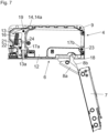
- Fig. 6 shows that the recess 17b of the coupling part 12 can be brought into engagement with the engagement element 23 of the mounting part 9 by a slight movement of the coupling part 12 in the direction of the longitudinal extension (L).
- the locking lever 13a of the locking device 13 and the ejection lever 14a of the ejection device 14 are formed together in one piece and are preferably prestressed by the same, single spring element 16.
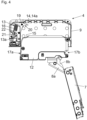
- Fig. 8 shows the release of the lock between the coupling part 12 and the mounting part 9 and the ejection of the coupling part 12 from the housing 11 of the mounting part 9 in an ejection direction (AR).
- the release element 25a is pressed into the housing 11 of the mounting part 9 by means of a tool, whereby the control element 22 is moved along the control curve 21 against the force of the spring element 16 and the spring element 16 is tensioned.
- the locking lever 13a of the locking device 13 is also moved out of the recess 17a of the coupling part 12, and the ejection lever 14a of the ejection device 14 is tilted about the rotation axis 19.
- the control element 22 springs back into the detent recess 24 of the control cam 21, whereby the coupling part 12 can be ejected from the housing 11 of the mounting part 9 in the ejection direction (AR) by the ejection lever 14a and the force of the relaxing spring element 16.
- At least one guide 26 is provided for the linear guidance of the release element 25a, through which the release element 25a can be guided in a direction perpendicular to the end face 18.
- the coupling part 12 is inserted substantially perpendicular to an end face 18 of the housing 11 of the mounting part 9, preferably wherein the coupling part 12 is moved substantially parallel to the end face 18 of the housing 11 of the mounting part 9 shortly before reaching an end position in the housing 11.
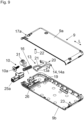
- Fig. 9 shows the mounting part 9 of the first fitting part 6 in an exploded view.
- the mounting part 9 has two interconnectable housing parts 9a, 9b, between which the locking device 13 with the locking lever 13a and the ejection device 14 are arranged.
- the armature 20 can be seen, on which the spring element 16 engages and on which the locking lever 13a and the ejection lever 14a are jointly formed.
- the control cam 21 for guiding the control element 22 is arranged or formed on the armature 20.
- the control cam 21 comprises a locking recess 24, by means of which the locking lever 13a can be releasably locked in the unlocked position.
- the mounting part 9 is to be fastened to a plate 5a-5e of the carrier 2 via at least one fastening device 10.
- the fastening device 10 can have a fastening element 10a and a clamping part 31 drivable by the fastening element 10a, by means of which the mounting part 9 can be fixed within a plate 5a-5e of the carrier 2.
Landscapes
- Engineering & Computer Science (AREA)
- Mechanical Engineering (AREA)
- Connection Of Plates (AREA)
- Hinges (AREA)
- Pivots And Pivotal Connections (AREA)
- Closing And Opening Devices For Wings, And Checks For Wings (AREA)
Applications Claiming Priority (3)
| Application Number | Priority Date | Filing Date | Title |
|---|---|---|---|
| ATA50950/2021A AT525172B1 (de) | 2021-11-26 | 2021-11-26 | Beschlag zur bewegbaren Lagerung eines Schwenkelementes relativ zu einem stationären Träger |
| EP22793628.3A EP4437210B1 (fr) | 2021-11-26 | 2022-10-13 | Raccord pour le montage mobile d'un élément pivot par rapport à un support fixe |
| PCT/AT2022/060354 WO2023092160A1 (fr) | 2021-11-26 | 2022-10-13 | Raccord pour le montage mobile d'un élément pivot par rapport à un support fixe |
Related Parent Applications (1)
| Application Number | Title | Priority Date | Filing Date |
|---|---|---|---|
| EP22793628.3A Division EP4437210B1 (fr) | 2021-11-26 | 2022-10-13 | Raccord pour le montage mobile d'un élément pivot par rapport à un support fixe |
Publications (2)
| Publication Number | Publication Date |
|---|---|
| EP4560099A2 true EP4560099A2 (fr) | 2025-05-28 |
| EP4560099A3 EP4560099A3 (fr) | 2025-08-06 |
Family
ID=83995330
Family Applications (2)
| Application Number | Title | Priority Date | Filing Date |
|---|---|---|---|
| EP25170611.5A Pending EP4560099A3 (fr) | 2021-11-26 | 2022-10-13 | Ferrure pour le montage mobile d'un élément pivotant par rapport à un support fixe |
| EP22793628.3A Active EP4437210B1 (fr) | 2021-11-26 | 2022-10-13 | Raccord pour le montage mobile d'un élément pivot par rapport à un support fixe |
Family Applications After (1)
| Application Number | Title | Priority Date | Filing Date |
|---|---|---|---|
| EP22793628.3A Active EP4437210B1 (fr) | 2021-11-26 | 2022-10-13 | Raccord pour le montage mobile d'un élément pivot par rapport à un support fixe |
Country Status (7)
| Country | Link |
|---|---|
| US (1) | US12497810B2 (fr) |
| EP (2) | EP4560099A3 (fr) |
| JP (1) | JP7721811B2 (fr) |
| CN (1) | CN118302589A (fr) |
| AT (1) | AT525172B1 (fr) |
| ES (1) | ES3031424T3 (fr) |
| WO (1) | WO2023092160A1 (fr) |
Families Citing this family (2)
| Publication number | Priority date | Publication date | Assignee | Title |
|---|---|---|---|---|
| USD1056697S1 (en) * | 2022-07-25 | 2025-01-07 | Julius Blum Gmbh | Furniture fitting |
| JP1752595S (ja) | 2022-07-25 | 2023-09-07 | 家具用部品用部材 |
Citations (4)
| Publication number | Priority date | Publication date | Assignee | Title |
|---|---|---|---|---|
| EP1895082A2 (fr) | 2006-05-19 | 2008-03-05 | Sugatsune Kogyo Co., Ltd. | Charnière avec membre de fixation |
| US20150061481A1 (en) | 2013-09-05 | 2015-03-05 | Wistron Corp. | Door device capable of switching statuses and storage equipment using the same |
| WO2020006589A1 (fr) | 2018-07-03 | 2020-01-09 | Julius Blum Gmbh | Ferrure pour meuble |
| WO2020006588A1 (fr) | 2018-07-03 | 2020-01-09 | Julius Blum Gmbh | Ferrure pour meuble |
Family Cites Families (12)
| Publication number | Priority date | Publication date | Assignee | Title |
|---|---|---|---|---|
| DE2723850C2 (de) * | 1977-05-26 | 1986-08-28 | Richard Heinze GmbH & Co KG, 4905 Spenge | Möbelscharnier |
| JPS57199676A (en) | 1981-06-03 | 1982-12-07 | Canon Inc | Nonimpaction type printer |
| JPS5912375Y2 (ja) * | 1981-06-15 | 1984-04-14 | 株式会社中尾製作所 | 扉を自在に着脱するための蝶番 |
| DE3525279A1 (de) | 1985-07-16 | 1987-01-29 | Lautenschlaeger Kg Karl | Moebelscharnier |
| JPS6268981A (ja) * | 1985-09-18 | 1987-03-30 | 余合住金産業株式会社 | 蝶番 |
| JP2726526B2 (ja) * | 1989-11-30 | 1998-03-11 | 株式会社ムラコシ精工 | ヒンジ |
| DE29703227U1 (de) * | 1997-02-24 | 1998-07-02 | Prämeta Gesellschaft für Präzisionsmetall- und Kunststofferzeugnisse mbH & Co KG, 51107 Köln | Schnellmontagetopf für Möbelscharniere |
| US7552511B2 (en) * | 2006-07-28 | 2009-06-30 | Creative Research & Development, Inc. | Adjustable hinge |
| US8234753B2 (en) * | 2008-10-24 | 2012-08-07 | L-3 Communications Integrated Systems L.P. | Cook hinge |
| PT3812545T (pt) * | 2015-04-30 | 2023-04-03 | Salice Arturo Spa | Dobradiça desacelerada para mobiliário |
| IT201700062317A1 (it) * | 2017-06-07 | 2018-12-07 | Effegi Brevetti Srl | Cerniera per mobili con dispositivo di regolazione della forza di chiusura |
| DE202018102088U1 (de) * | 2018-04-17 | 2019-07-18 | Grass Gmbh | Vorrichtung zur Bewegung eines Möbelteils und Möbel |
-
2021
- 2021-11-26 AT ATA50950/2021A patent/AT525172B1/de active
-
2022
- 2022-10-13 WO PCT/AT2022/060354 patent/WO2023092160A1/fr not_active Ceased
- 2022-10-13 ES ES22793628T patent/ES3031424T3/es active Active
- 2022-10-13 EP EP25170611.5A patent/EP4560099A3/fr active Pending
- 2022-10-13 JP JP2024531381A patent/JP7721811B2/ja active Active
- 2022-10-13 EP EP22793628.3A patent/EP4437210B1/fr active Active
- 2022-10-13 CN CN202280077711.1A patent/CN118302589A/zh active Pending
-
2024
- 2024-04-26 US US18/647,765 patent/US12497810B2/en active Active
Patent Citations (4)
| Publication number | Priority date | Publication date | Assignee | Title |
|---|---|---|---|---|
| EP1895082A2 (fr) | 2006-05-19 | 2008-03-05 | Sugatsune Kogyo Co., Ltd. | Charnière avec membre de fixation |
| US20150061481A1 (en) | 2013-09-05 | 2015-03-05 | Wistron Corp. | Door device capable of switching statuses and storage equipment using the same |
| WO2020006589A1 (fr) | 2018-07-03 | 2020-01-09 | Julius Blum Gmbh | Ferrure pour meuble |
| WO2020006588A1 (fr) | 2018-07-03 | 2020-01-09 | Julius Blum Gmbh | Ferrure pour meuble |
Also Published As
| Publication number | Publication date |
|---|---|
| EP4437210A1 (fr) | 2024-10-02 |
| WO2023092160A1 (fr) | 2023-06-01 |
| JP2024540662A (ja) | 2024-10-31 |
| EP4437210B1 (fr) | 2025-04-16 |
| AT525172A4 (de) | 2023-01-15 |
| US12497810B2 (en) | 2025-12-16 |
| EP4560099A3 (fr) | 2025-08-06 |
| JP7721811B2 (ja) | 2025-08-12 |
| AT525172B1 (de) | 2023-01-15 |
| US20240271473A1 (en) | 2024-08-15 |
| CN118302589A (zh) | 2024-07-05 |
| ES3031424T3 (en) | 2025-07-08 |
Similar Documents
| Publication | Publication Date | Title |
|---|---|---|
| AT507577B1 (de) | Möbelbeschlag zum lösbaren verbinden zweier möbelteile | |
| EP3818225B1 (fr) | Ferrure pour meuble | |
| EP1785062B1 (fr) | Guide telescopique destiné à des tiroirs et le tiroir | |
| AT521436B1 (de) | Möbelbeschlag | |
| EP4437207B1 (fr) | Raccord pour le montage mobile d'un élément pivotant par rapport à un support fixe | |
| AT506542A1 (de) | Verriegelbare ausstossvorrichtung für ein in einem möbel bewegbar gelagertes möbelteil | |
| EP4437210B1 (fr) | Raccord pour le montage mobile d'un élément pivot par rapport à un support fixe | |
| DE69020604T2 (de) | Verborgene Vorrichtung zur Wandmontage eines Wandmöbelelementes. | |
| EP1959792A1 (fr) | Meuble presentant au moins des premiere et deuxieme parties de meuble | |
| EP2250929A1 (fr) | Elément d'armoire doté d'un élément de sortie rétractable | |
| WO2009114886A1 (fr) | Dispositif de fixation destiné à arrêter un élément de meuble logé mobile dans ou contre un meuble | |
| DE102005034833A1 (de) | Verschluß mit Ratschenklinke | |
| EP3899289A1 (fr) | Dispositif d'entraînement de meuble | |
| AT501396B1 (de) | Falttürenscharnier | |
| DE69411452T2 (de) | Vorrichtung zum Befestigen und Seitenjustieren der Frontverkleidung einer Schublade | |
| AT402794B (de) | Skibindung mit einer arretiervorrichtung für vorder- und/oder fersenbacken | |
| DE102013001818A1 (de) | Gegenkasten | |
| DE4307911A1 (de) | Rollschubkastenregal | |
| DE202009016669U1 (de) | Möbel, Möbelteil und Vorrichtung zur Verbindung eines Frontbauteils eines Möbelteils | |
| DE4239599C2 (de) | Handbetätigte Verschließvorrichtung für Wagenkästen und Container | |
| EP1024240B1 (fr) | Dispositif de verrouillage | |
| AT526823B1 (de) | Ausziehführung | |
| EP0199270A2 (fr) | Dispositif pour maintenir une porte ou une fenêtre entrouverte dans au moins une position | |
| DE69718264T2 (de) | Schaltschrank mit einem Schaltfach zur Unterbringung einer ausziehbaren Arbeitsplatte | |
| DE3025344A1 (de) | Moebelscharnier |
Legal Events
| Date | Code | Title | Description |
|---|---|---|---|
| PUAI | Public reference made under article 153(3) epc to a published international application that has entered the european phase |
Free format text: ORIGINAL CODE: 0009012 |
|
| STAA | Information on the status of an ep patent application or granted ep patent |
Free format text: STATUS: THE APPLICATION HAS BEEN PUBLISHED |
|
| AC | Divisional application: reference to earlier application |
Ref document number: 4437210 Country of ref document: EP Kind code of ref document: P |
|
| AK | Designated contracting states |
Kind code of ref document: A2 Designated state(s): AL AT BE BG CH CY CZ DE DK EE ES FI FR GB GR HR HU IE IS IT LI LT LU LV MC ME MK MT NL NO PL PT RO RS SE SI SK SM TR |
|
| PUAL | Search report despatched |
Free format text: ORIGINAL CODE: 0009013 |
|
| AK | Designated contracting states |
Kind code of ref document: A3 Designated state(s): AL AT BE BG CH CY CZ DE DK EE ES FI FR GB GR HR HU IE IS IT LI LT LU LV MC ME MK MT NL NO PL PT RO RS SE SI SK SM TR |
|
| RIC1 | Information provided on ipc code assigned before grant |
Ipc: E05D 7/12 20060101AFI20250703BHEP |