EP4437385B1 - Kopplungsverfahren für redundante servovorrichtungen eines aktuatorsteuerungssystems, zugehöriges system und vorrichtung - Google Patents
Kopplungsverfahren für redundante servovorrichtungen eines aktuatorsteuerungssystems, zugehöriges system und vorrichtung Download PDFInfo
- Publication number
- EP4437385B1 EP4437385B1 EP23786641.3A EP23786641A EP4437385B1 EP 4437385 B1 EP4437385 B1 EP 4437385B1 EP 23786641 A EP23786641 A EP 23786641A EP 4437385 B1 EP4437385 B1 EP 4437385B1
- Authority
- EP
- European Patent Office
- Prior art keywords
- values
- redundant
- value
- variable
- control system
- Prior art date
- Legal status (The legal status is an assumption and is not a legal conclusion. Google has not performed a legal analysis and makes no representation as to the accuracy of the status listed.)
- Active
Links
Images


Classifications
-
- G—PHYSICS
- G05—CONTROLLING; REGULATING
- G05B—CONTROL OR REGULATING SYSTEMS IN GENERAL; FUNCTIONAL ELEMENTS OF SUCH SYSTEMS; MONITORING OR TESTING ARRANGEMENTS FOR SUCH SYSTEMS OR ELEMENTS
- G05B9/00—Safety arrangements
- G05B9/02—Safety arrangements electric
- G05B9/03—Safety arrangements electric with multiple-channel loop, i.e. redundant control systems
-
- B—PERFORMING OPERATIONS; TRANSPORTING
- B64—AIRCRAFT; AVIATION; COSMONAUTICS
- B64C—AEROPLANES; HELICOPTERS
- B64C19/00—Aircraft control not otherwise provided for
-
- G—PHYSICS
- G05—CONTROLLING; REGULATING
- G05B—CONTROL OR REGULATING SYSTEMS IN GENERAL; FUNCTIONAL ELEMENTS OF SUCH SYSTEMS; MONITORING OR TESTING ARRANGEMENTS FOR SUCH SYSTEMS OR ELEMENTS
- G05B6/00—Internal feedback arrangements for obtaining particular characteristics, e.g. proportional, integral or differential
- G05B6/02—Internal feedback arrangements for obtaining particular characteristics, e.g. proportional, integral or differential electric
Definitions
- the invention relates to the field of servo systems for an actuator.
- servo system means any system designed to reach a setpoint value as quickly as possible and to maintain it regardless of the disturbances caused by the system's environment as far as possible.
- the invention relates more particularly to the field of such servo systems when the latter are said to be “redundant” or “multiple redundant” to be used, for example, in land, water or air vehicles.
- EP0645026A1 illustrates the state of the art.
- Such an aircraft is generally in the form of a propulsion device, preferably but not limited to vertical propulsion, adapted or arranged to ensure elevations and movements of a load whether it consists of a pilot, one or more human or animal passengers and/or one or more solid or fluid goods whose propulsion device would ensure the transport.
- a propulsion device preferably but not limited to vertical propulsion, adapted or arranged to ensure elevations and movements of a load whether it consists of a pilot, one or more human or animal passengers and/or one or more solid or fluid goods whose propulsion device would ensure the transport.
- the principle of a control of a quantity or a characteristic thereof generally consists of measuring said quantity produced by a system and comparing it to a setpoint value. In order for said quantity produced to reach the target value determined by the setpoint value as quickly as possible and then to be maintained, said setpoint is corrected in light of the difference between the value produced by the system and said setpoint value.
- Some control systems by control act on one or more characteristics of such a controlled quantity such as position, speed or acceleration. Such systems are for this reason sometimes described as “negative feedback” or “counter-reaction” or “closed loop” control systems. It is also possible to control different quantities and/or characteristics of the latter to ultimately produce a command for an actuator.
- the concepts of stability and precision are often antagonistic to the concept of speed.
- a corrector in the control loop.
- correctors There are different types of correctors whose action can be integral, derivative and/or proportional to the difference measured between the controlled quantity and the setpoint.
- PID corrector an acronym for "Proportional, Integral, Derivative”.
- Such a regulator is parameterized by means of gains or coefficients to weight the corrective actions respectively proportional to said difference, to the integral and to the derivative of the latter.
- the action that we can describe as "proportional” contributes directly to the responsiveness and stability of the control.
- the “integral” action makes it possible to erase a residual error and brings precision to the system and the “derivative” action makes it possible to limit oscillations around the set point of the controlled quantity.
- such servo systems may have multiple redundancy and require a plurality of arbitration devices for such multiple redundancy.
- redundancy In engineering, the concept of "redundancy” consists of the duplication of critical components or functions of a system in order to increase the reliability of said system.
- certain parts of a control system of the latter may be doubled or tripled, in which case we speak of a double or triple redundancy system.
- an error generated by an element linked for example to a malfunction or a drift in the performance of said element can then be cancelled or compensated by the use of one or more other redundant elements.
- a multiple redundancy system is also known as a “multiple redundancy system”. “vote/majority logic” or “voting logic system” to exploit multiple production of the same quantity in order to control an actuator for example.
- the invention provides a method implemented by a processing unit of a servo device among several devices.
- redundant servocontrol devices of an actuator control system each redundant servocontrol device respectively producing values of the same quantity from the same setpoint and the same measurement data, said produced values being used by said system to control the actuator, said redundant servocontrol devices being mutually in communication so that each redundant servocontrol device has read access to the last values of said quantity produced by said redundant servocontrol devices.
- the step of determining the reference value consists of: advantageously in choosing the median of the values of the set of current values of the quantity.
- the step of determining the reference value may consist of choosing one of the values from the set of current values of the quantity.
- the value of the correction coefficient can be predetermined.
- a method according to the invention may comprise a step of recording the current or corrected value of the quantity produced in a data memory of the servo device to constitute a history of a determined number of values. Such a method then comprises, prior to the correction step, a step of producing the value of the correction coefficient which is a function of the variability of the values taken from said history and of the iteration frequency of the step of reading the last known values of the quantity produced by the redundant servo devices.
- the calculation of the value of the correction is arranged so that said value of the correction does not exceed in absolute value a predetermined limit value.
- the redundant servo devices each comprise a PID corrector delivering three components of an output signal describing respectively a proportional action, an integral action and a derivative action
- the quantity can consist of the component describing said integral action of said PID corrector.
- the invention relates to a servo device among several redundant servo devices of a control system of an actuator, said redundant servo devices each producing a value of the same quantity from the same setpoint and the same measurement data, said redundant servo devices being furthermore mutually in communication so that each servo device accesses in reading the last values of said quantity produced by the redundant servo devices.
- Said servo device is arranged to implement a method according to the invention.
- the invention relates to a system for controlling an actuator comprising several redundant servo devices in accordance with the preceding claim, said actuator control being produced from the plurality of values of the quantity produced jointly by the redundant servo devices.
- the invention relates to a vehicle with a load consisting of a driver, a passenger and/or goods or merchandise comprising one or more actuators in the form of at least one thrust group for moving said vehicle, a command of which is produced by a control system according to the invention.
- such a vehicle may be an aircraft.
- the invention further relates to a computer program product comprising one or more program instructions interpretable by a processing unit of a servo device among a plurality of redundant servo devices of a control system of an actuator according to the invention.
- said program instructions are loadable into a non-volatile memory of the servo device and designed so that their execution by said processing unit causes the implementation of a method according to the invention.
- the invention relates to a storage medium readable by such a processing unit comprising the instructions of such a computer program product.
- such a propulsion device may consist of a drone, a quadcopter or an octocopter.
- the document EP 3495262 A1 describes an example of such a propulsion device.
- the invention should not, however, be limited to these examples of application alone and could, instead, be used in connection with any type of device for propelling a load, a pilot or a passenger.
- such a vertical take-off/landing aircraft is powered by a plurality of thrust groups. It is distinguished from that taken from the document EP3495262A1 in that the respective actuation commands of said thrust groups are produced by a multiple redundancy control system.
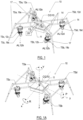
- the four thrust groups 12a, 12b, 12c, 12d respectively deliver thrust vectors AL12a, AL12b, AL12c, AL12d, substantially normal to the platform 11.
- the arms of the support means 14 of the thrust systems TSa, TSb, TSc and TSd cooperate, at their respective distal parts, with projecting means or advantageously telescopic feet 17.
- the fluid outlets of the thrusters of the thrust systems are positioned above or below, substantially at the level of the center of gravity CG10 of the device 10 according to the configuration and arrangement of the support means 14.
- each thrust system TSa to TSd comprises correction means 19a, 19b, 19c, 19d of the thrust vectors AL12a, AL12b, AL12c, AL12d delivered respectively by the turbojets of the thrust groups 12a to 12d.
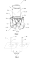
- FIG 2 illustrates the arrangement of such thrust vector correcting means 19a of the thrust group 12a of the TSa thrust system according to the figure 1 .
- Said thrust vector correcting means 19a comprise a pair of deflector guides 19a-1 and 19a-5 mounted movably, more precisely via respective pivot links 19a-2 and 19a-6.
- Said deflector guides 19a-1 and 19a-5 are arranged to deflect all or part of the thrust vector AL12a at a region close to the fluid ejection outlet 12a-o of the turbojet 12a-e of the thrust group 12a.
- the deflector assembly composed of the deflector guides 19a-1 and 19a-5 thus makes it possible to describe a “pinching” of said thrust vector AL12a.
- the deflector guides 19a-1 and 19a-5 are advantageously actuated respectively by a pair of cam actuators or servomotors, of which only the actuator 19a-3 is visible in the figure 1 .
- the actuator 19a-3 cooperates via a connecting rod 19a-4 with the deflector guide 19a-1.
- Actuation of the actuator cam 19a-3 causes a rotational movement r of the deflector guide 19a-1 about the axis 19a-2 located above the fluid ejection region of the turbojet engine 12a, which reduces the torque required by the actuator 19a-3 to overcome and resist the suction or rejection generated by the thrust vector AL12a delivered by the turbojet engine 12a-e of the thrust group 12a during the closing and opening of the deflector guide 19a-1.
- said thrust vector AL12a is subdivided downstream of said deflector guides into two or three components AL12a, AL12a', AL12a" depending on whether or not such or such deflector guide 19a-1 or 19a-5 penetrates the flow ejected at the fluid outlet 12a-o of the turbojet 12a-e.
- the force of said thrust vector AL12a is maximum.
- the latter may be arranged to respectively guide fluid flows causing at the outlet (distal parts) of said guides, vectors secondary thrust vectors AL12a' and AL12a" oriented in directions substantially opposite to the direction of the original thrust vector AL12a at the fluid ejection outlet 12a-o of the turbojet 12a-e.
- the thrust systems TSa to TSd of the aircraft 10 could each consist of a propeller driven in rotation by an electric and/or thermal engine to deliver thrust equivalent to that described by a thrust system based on a turbojet as described in connection with the Figures 1 and 1A .
- an electronic control system 30 controls the respective powers of the thrust systems TSa to TSd from measurements delivered by an inertial unit 40 advantageously positioned near the center of gravity CG10 of the aircraft 10 and from piloting instructions delivered by an instruction unit 20 in communication CL, wired or radio, with the control system 30.
- the latter thus translates the pilot's directives, via the instruction unit 20, into control of actuators (thrusters, deflectors) to regulate the thrusts respectively delivered by the thrust systems TSa to TSd causing the trajectory of the aircraft 10 required by said pilot with regard to the attitude and position of said aircraft estimated by the measurement unit 40.
- FIG. 1A describes such an aircraft 10 in light of a reference frame determined by three axes x, y, z respectively inscribed in the plane of the platform 11 for the x and y axes and normal to the latter for the z axis.
- the three axes x, y and z are intersecting at the center of gravity CG10 of the aircraft 10.
- the x axis extends from the stern to the bow of the aircraft and the y axis extends from starboard to port.
- the z axis describes a vertical, from the distance to the ground, when the platform is horizontal.
- Such an aircraft 10 can move in the air according to rotations R, P, Y caused respectively around said axes x, y and z by the control system 30 deliberately regulating the respective thrusts delivered by the thrust groups TSa to TSd.
- a vertical rise of the aircraft 10 is caused by a joint and identical increase in the thrusts delivered by the four thrust groups TSa to TSd, sufficient increase to create a lift force greater than the weight of the aircraft 10.
- a vertical displacement from top to bottom of the aircraft is obtained by a joint and identical reduction of the thrusts delivered by the four thrust groups TSa to TSd to create a lift force less than the weight of the aircraft 10.
- the control system 30 induces a thrust difference between the thrust group pairs respectively formed by the thrust groups TSa and TSd for one and by the thrust groups TSb and TSc for the other.
- a rotation P also known as “pitch” or “pitching” according to English terminology, around the y axis is caused.
- a relative and conjugate increase in the torque ⁇ TSa, TSd ⁇ with respect to the torque ⁇ TSb, TSc ⁇ caused by a positive thrust differential induces a forward movement of the aircraft.
- the converse induces a rearward movement of the aircraft 10.
- the control system 30 induces a thrust difference between the thrust group pairs respectively formed by the thrust groups TSa and TSc for one and by the thrust groups TSd and TSb for the other.
- a rotation R also known as a “roll” or “roll” according to English terminology, around the x axis is caused.
- a relative and conjugate increase in the torque ⁇ TSa, TSc ⁇ with respect to the torque ⁇ TSb, TSd ⁇ caused by a positive thrust differential induces a movement to port of the aircraft 10.
- the converse induces a movement of the aircraft 10 to starboard.
- the control system 30 can also cause a Y rotation, also known as “yaw” or “yaw” according to English terminology, of the aircraft around the z axis.
- a Y rotation also known as "yaw” or "yaw” according to English terminology
- the control system 30 induces an asymmetric pinching of the deflector guides of each thrust group TSa to TSd, of at least a torque ⁇ TSa, TSb ⁇ or ⁇ TSc, TSd ⁇ of thrust groups.
- the control system 30 causes an increase equal to the decrease in the combined thrusts delivered by the pair or pairs of thrust groups concerned by such asymmetric pinching of their deflector guides so that the overall lift force delivered by all of the thrust groups is constant.
- a setpoint unit 20 may consist of a human-machine input interface comprising input peripherals in the form of a pair of joysticks or levers 21 and 22.
- the invention cannot be limited by this sole choice of input peripherals, the latter being able to further or alternatively comprise a plurality of buttons, a touch surface or any other equivalent and suitable means.
- a setpoint unit 20 further comprises electronic means 23, such as one or more microcontrollers or microprocessors, for translating such movements of the distal parts 21d and 22d of the levers 21 and 22 into electrical setpoint signals Gsp, the latter being intended for be routed to the control system 30 by radio or wire CL.
- electronic means 23 can be duplicated in several redundant means and jointly produce a plurality of Gsp setpoint signals.
- Said instruction unit 20 may further comprise other members such as push buttons, for example, to translate an order to start the thrusters, to signify a loss of ability of the pilot to pilot the aircraft, to switch from a manual piloting mode to an assisted piloting mode, etc.
- Said electronic means 23 of the instruction unit 20 are arranged to also communicate the information delivered by said members.
- said instruction unit 20 may transmit a Gsp signal, or even a plurality of signals Gsp if the means 23 are redundant, for example of the PPM type, conveying a vector of information among which we can cite position instructions Xsp, heading/yaw ⁇ sp, start or stop instructions for the thruster(s), a piloting mode identifier, etc.
- FIG 4 describes a system 30 for controlling TS actuators, for example the thrust groups TSa to TSd of an aircraft 10 according to the figure 1 .
- Said control system 30 integrates or cooperates with one or more inertial units 40 (accelerometers, gyroscopes, magnetometers), inertial navigation units (INU, an English acronym for “Inertial Navigation Unit”), or even inertial measurement units (IMU, an English acronym for “Inertial Measurement Unit”).
- INU an English acronym for “Inertial Navigation Unit”
- IMU inertial measurement units
- Such a measurement unit 40 is designed in particular to estimate the positions X ⁇ , linear speeds V ⁇ or angular speeds ⁇ of the aircraft 10.
- the linear speed V ⁇ , the position X ⁇ can be estimated with respect to the “NED Frame” (for North-East-Down according to English terminology) reference frame determined by three orthogonal axes in which a first axis points towards geographic north, a second axis points towards the center of the earth and the third axis points towards the east.
- the attitude ⁇ and quaternion q ⁇ as well as any angular velocity ⁇ of the aircraft are generally estimated with respect to an aircraft-specific reference frame 10 such as that illustrated by the x, y, z axes on the Figure 1A . Said linear velocities and said positions are possibly corrected by a Kalman filter.
- the control system 30 comprises one or more flight controllers FC whose role is to integrate the measurements delivered by the measurement unit(s) 40 and the piloting instructions delivered by the instruction unit 20 to deliver to each thrust group TSa to TSd (or more generally to an actuator TS) a command ⁇ , for example in the form of a PPM signal or equivalent, capable of mainly conveying components relating to the pitch ⁇ p, the roll ⁇ r, the yaw ⁇ y, the power/thrust ⁇ t.
- a command ⁇ for example in the form of a PPM signal or equivalent, capable of mainly conveying components relating to the pitch ⁇ p, the roll ⁇ r, the yaw ⁇ y, the power/thrust ⁇ t.
- FC flight controller for an aircraft such as the drone 10 illustrated by the figure 1 .
- said FC flight controller comprises a plurality of control devices constituting two main stages, referenced STA and STB on the figure 4 .
- STA stage is responsible for regulating the position of the aircraft in the “NED Frame” reference frame.
- the STA stage globally produces a setpoint acceleration Asp from, on the one hand, measurements emanating from a measurement unit 40, in this case estimates of the position X ⁇ and the linear speed V ⁇ of the aircraft and, on the other hand, position setpoints Xsp delivered by a setpoint unit 20 such as that previously described in connection with the figures 3 And 3A .
- the STB stage is responsible for regulating the position of the aircraft in a frame of reference, called a "Body frame" according to English terminology, specific to the aircraft platform 10 as illustrated by the x, y, z axes on the Figure 1A to deliver actuator control components ⁇ relating to pitch ⁇ p, roll ⁇ r, yaw ⁇ y from, on the one hand, the production of the STA step (setpoint acceleration Asp), the heading/yaw setpoints ⁇ sp emanating from the control unit and, on the other hand, from measurements delivered by the measurement unit 40 in terms of attitude ⁇ , quaternion q ⁇ , and angular velocity ⁇ .
- an interface 33 provides a transposition of reference points so that the acceleration setpoint Asp and the heading/yaw setpoints ⁇ sp are translated into a quaternion setpoint qsp and into a component ⁇ t of the command ⁇ relating to the power/thrust.
- Each STA and STB stage can be "clocked" according to distinct periods or frequencies.
- the regulation frequencies implemented by the two main STA and STB stages can be fifty hertz for the STA stage and two hundred and fifty to one thousand hertz for the STB stage.
- each of said stages STA and STB comprises two control devices respectively 31, 32 for the STA stage and 34, 35 for the STB stage.
- the aircraft position control device 31 delivers a set speed Vsp from the difference between a set position Xsp and an estimated position X ⁇ . This set speed Vsp is then compared by the control device 32 to the estimated linear speed V ⁇ by the measurement unit 40 in order to produce the set acceleration Asp previously mentioned.
- the attitude control device 34 of the STB stage delivers a set angular speed ⁇ sp by comparing the set quaternion qsp and the estimates of the quaternion q ⁇ and the attitude ⁇ delivered by the measurement unit 40.
- This set angular speed ⁇ sp is then compared to the angular speed of the aircraft estimated ⁇ by said measurement unit 40 to ultimately produce the components of the control vector ⁇ relating to the pitch ⁇ p, the roll ⁇ r and the yaw ⁇ y by the angular speed control device 35 of the STB stage.
- the position 31 and attitude 34 control devices generate respective outputs proportional to the differences separating their inputs.
- the linear and angular speed control devices 32 and 35 produce outputs from components describing corrective actions respectively proportional to the difference between their inputs, to the integral and to the derivative of said difference, for example by using a PID regulator.
- Each control device can advantageously include its own processing unit Ut (for example, in the form of one or more microprocessors or microcontrollers cooperating with a data and/or program memory M) which samples, according to a given periodicity, the measurements and/or instructions delivered by the measurement unit 40 and/or the instruction unit 20 or more generally by sources delivering instructions or measurement data.
- Such a source which we can call a "instruction source” can thus consist of a instruction unit 20 as described above in connection with the figure 3 .
- Such a setpoint source may further consist of a position control device 31 or attitude control device 34, or even the interface 33, for the linear speed control modules 31 and angular speed control modules 35.
- such a flight controller FC may comprise only a single processing unit Ut responsible for implementing production processes specific to the various electronic elements (position controllers 31, attitude controllers 34, linear speed controllers 32 or angular speed controllers 35, or even the interface 33).
- the processing unit Ut of a flight controller is centralized or decentralized, that is to say that all or part of the various electronic elements of the latter comprises its own processing unit Ut (the figure 4 illustrates such a situation for the control modules 34 and 35)
- the behavior of a processing unit Ut can be advantageously determined by means of a suitable computer program whose program instructions are loaded into the data and/or program memory(ies) M cooperating with said processing unit.
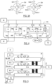
- FIG. 5 illustrates an embodiment of such a control system 30 of an actuator TS according to the invention for which elements of measurements, communication and/or data processing are duplicated for reliability reasons.
- three flight controllers FC-1, FC-2 and FC-3 similar to the FC controller described above in connection with the figure 4 , are arranged within said control system 30 to carry out similar processing operations from measurement data emanating from a measurement unit 40 and from setpoint data delivered by a setpoint unit 20.
- the three flight controllers FC-1 to FC-3 are thus individually responsible for producing a command ⁇ 1, ⁇ 2 or ⁇ 3 of an actuator TS such as the thrust groups TSa to TSd of an aircraft 10 already described in connection with the figure 1 .
- Said commands ⁇ 1, ⁇ 2 or ⁇ 3 thus collectively form the command ⁇ of the control system 30.
- a control system 30 is arranged so that said commands ⁇ 1, ⁇ 2 and ⁇ 3 are jointly produced by the redundant flight controllers.
- said three flight controllers FC-1, FC-2 and FC-3 are arranged to be in mutual communication via a communication bus B so that each flight controller knows the values produced by its peers.
- control devices (such as the devices 31, 32, 34 and 35 illustrated by the figure 4 ) respectively composing the latter and ensuring the position, attitude, linear and angular speed regulations can have the capacity to know themselves the data produced by their peers within the different flight controllers FC-1 to FC-3.
- a communication bus B can consist of a data bus called CAN (acronym for the English expression "Controller Area Network”), advantageously redundant, that is to say for example doubled for reasons of reliability.
- CAN acronym for the English expression "Controller Area Network”
- Such a technological choice is advantageous for routing via a single cable, a large amount of data and share them between the different electronic elements of the control system 30.
- such a control system may be arranged such that a “simple” ⁇ command can be generated directly by the control system from the plurality ⁇ of orders ⁇ 1, ⁇ 2 and ⁇ 3 produced respectively and jointly by the three flight controllers FC-1, FC-2 and FC-3, in order to relieve the actuator TS of such an arbitration task.
- a control system 30 may comprise an arbitration means (not shown for the sake of simplification on the figure 5 ) to develop such a ⁇ command using a technique similar to that previously described for the arbitration that an actuator can perform.
- the measuring unit 40 can also be multiplied in the form of three redundant measuring units 40-1, 40-2, 40-3 delivering their measurements respectively to the three flight controllers FC-1, FC-2, FC-3.
- the latter can propagate to their peers, via the communication bus B, the measurement data delivered by the measuring unit dedicated to each flight controller.
- the measuring unit 40-1 delivers to the flight controller FC-1 measurement data Gs1 in the form of position estimates X1 ⁇ , linear speeds V1 ⁇ and angular ⁇ 1 ⁇ of aircraft 10, attitude ⁇ 1 ⁇ and quaternion q1 of the latter.
- the measuring unit 40-2 delivers to the flight controller FC-2 measurement data Gs2 in the form of estimates of the position X2 ⁇ , linear speeds V2 ⁇ and angular ⁇ 2 ⁇ of aircraft 10, attitude ⁇ 2 ⁇ and quaternion q 2 ⁇ of the latter.
- the 40-3 measuring unit delivers to the FC-3 flight controller Gs3 measurement data in the form of position estimates X3 ⁇ , linear speeds V3 ⁇ and angular ⁇ 3 ⁇ of aircraft 10, attitude ⁇ 3 ⁇ and quaternion q3 ⁇ of the latter.
- the three measuring units 40-1, 40-2, 40-3 could be connected via the communication bus B to the three flight controllers FC-1, FC-2, FC-3.
- the instruction unit 20 delivers to the three flight controllers FC-1, FC-2 and FC-3 the instructions Gsp relating to the positions Xsp, headings and yaw ⁇ sp.
- Such an instruction can also be plural Gsp when said consignment unit has multiple redundancy.
- the figure 5 also illustrates the possible presence of a module navigation assistance unit 20a which can, as a supplement, assist the pilot and deliver Gsp instructions relating to positions Xsp, headings and yaw ⁇ sp instead of or in addition to the instruction unit 20.
- the three flight controllers FC-1, FC-2 and FC-3 would be perfectly identical, would have the capacity to sample the data or signals carried by the data bus B at an infinite frequency and would thus share their produced data with their peers instantly.
- the measurement units would deliver identical and noise-free estimates.
- this ideal world is utopian. There are therefore latencies between the reading or sampling carried out by each flight controller, of the data produced by its peers and the production of its own data.
- the invention provides for distributing at the level of each flight controller FC-1, FC-2, FC-3 within the control system 30, or even distributing at the level of each control device 31, 32, 34, 35 of each of said flight controllers FC-1, FC-2, FC-3, a method for correcting the values of quantities produced which takes into account the productions of peer control devices and/or flight controllers. Thanks to the implementation of such a method according to the invention, the commands ⁇ 1, ⁇ 2 and ⁇ 3 become jointly produced by the flight controllers FC-1, FC-2, FC-3 do not diverge in nominal operation (i.e. in accordance with the constraints of design), leaving the TS actuator to take into account coherent and precise ⁇ 1, ⁇ 2 and ⁇ 3 commands.
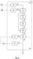
- Such a method 100 comprises a first step 110 of producing the value Gl of a quantity G from a setpoint Gsp and a measurement datum Gs.
- said servo device implementing said method 100 may consist of the flight controller FC-1, the flight controllers FC-2 and FC-3 being the even servo devices of the controller FC-1.
- the quantity G mentioned is the actuator control ⁇ , the value GI thereof being alternately the command ⁇ 1 when said servo device implementing the method 100 is the controller FC-1 or the command ⁇ 2 when, for its part, the servo device FC-2 implements said method 100, the flight controllers FC-1 and FC3 being the even servo devices of the latter, and so on for the flight controller FC-3.
- the set G consists of the commands ⁇ 1, ⁇ 2 and ⁇ 3.
- the Gsp setpoint consists of the components relating to the position Xsp, heading and yaw ⁇ sp emanating from a setpoint unit such as unit 20 according to the figure 5
- the measurement data Gs consists of all the estimates of position X ⁇ , linear speed V ⁇ , attitude ⁇ and quaternion q, as well as the angular speed ⁇ delivered by a measurement unit 40 according to said figure 4 , or even in the estimates delivered respectively by the redundant measurement units 40-1, 40-2 and 40-3 according to the example illustrated by the figure 5 .
- the redundant servo devices implementing said method 100 may be the respective linear speed controllers 32 of the flight controllers FC-1 and FC-2 and FC-3, or even the respective angular speed controllers 35 of said flight controllers FC-1 and FC-2 and FC-3 (when the latter are constituted like the flight controller FC illustrated by the figure 4 ).
- the quantity G is a setpoint acceleration Asp, or more precisely the component of the latter reflecting the integral action when said speed controller 32 comprises a PID regulator.
- the setpoint Gsp consists of the setpoint linear speed Vsp, itself produced by a position controller of said flight controller FC-1, FC-2 or FC-3 concerned. All of the values G consists of the Asp setpoint accelerations produced by the 32-pair speed control devices or by only the components of said Asp setpoint acceleration reflecting the integral action of the PID regulators of the pair speed controllers.
- said redundant servo devices implementing a method 100 according to the invention may consist of the respective position control devices 31 of the flight controllers FC-1, FC-2 and FC-3.
- the quantity G considered is then the setpoint linear speed Vsp.
- the setpoint Gsp consists of the components relating to the positions Xsp, heading and yaw ⁇ sp emanating from a setpoint unit 20, the measurement data Gs being the position of the aircraft estimated by a measurement unit 40, 40-1, 40-2, 40-3.
- a method 100 further comprises a step 130 of determining a reference value Gr of said quantity taken from the whole G , that is to say selected from the values forming said set G at step 120.
- the actuator control system 30 the elements of which each implement said method 100 in a distributed manner, comprises at least three redundant servo devices (such as the controllers FC-1, FC-2, FC-3 or the position, attitude and/or linear or angular speed controllers of the latter) capable of producing and communicating a value of the quantity G
- the invention provides that the step 130 of determining the reference value Gr can consist in determining the median of said values forming the set G of the current values of the quantity G.
- the term "median" means the midpoint of a data set, in this case the set G, such that fifty percent of said data have a value less than or equal to the median and fifty percent of said data have a value greater than or equal to said median.
- the median is the position of a value once the set G ordered: the smallest value corresponds to the first rank, the second smallest value to the second rank, etc.
- the median will therefore be chosen as the value of the second-rank quantity or the intermediate value between the two minimum and maximum values. Opting for the median makes it possible to avoid aberrations generated according to certain previous techniques which favor the average or a unitary selection, when a production of one of the servo devices deviates clearly with respect to the others.
- step 130 of determining the reference value Gr consists of choosing, within the set G of current values of the quantity G, one of the current values of said quantity produced by the first or second servo device remaining capable of producing a value of the quantity G. Such a choice may be made on the servo device with the lowest index, when said redundant servo devices are identified by such an index or according to any other technique opting for alternation or a random choice.
- a method 100 therefore comprises a step 140 of calculating a difference Ge between the current value GI of the quantity G produced in step 110 and said reference value Gr then a step 150 of producing a corrected current value Gl' of the quantity G consisting of implementing an operation of subtracting a correction Gc.
- the latter value consists of a calculation according to which said difference Ge is multiplied by a correction coefficient Kc of said current value GI resulting from step 110.
- the final production GI' of each of the redundant servo devices is coupled to those of the other redundant servo devices.
- the latter jointly produce corrected GI' values of the quantity G.
- the value of the correction coefficient Kc which induces a coupling of the respective productions of the redundant servo devices can be predetermined and for example recorded in a memory M of each servo device.
- the choice of said value of the correction coefficient Kc induces various remarkable technical effects on the desired behavior for the control system 30 as we will see later in connection with the figures 7 , 7A And 8 .
- said value of the correction coefficient Kc may be chosen as equal to one, meaning that the entirety of the difference Ge between the current value GI of the quantity G produced by one of the devices redundant servo devices and the reference value Gr, is subtracted from said current value GI, the latter taking as its value, said reference value Gr.
- said correction coefficient value Kc can be chosen, empirically, for example according to a criterion based on the variability of the quantity G with respect to the frequency SP to sample, in step 120, the values produced by the even servo device(s), i.e.
- a correction coefficient Kc of low value for example of the order of five percent, will be preferred for a quantity G whose values vary intensely with respect to the frequency SP and conversely a coefficient close to or equal to one hundred percent in the opposite case.
- a low correction coefficient Kc may also be chosen in the presence of a large latency between the current values produced by the different redundant servo devices to constitute the sets G and a value close to or equal to one hundred percent otherwise. It is thus possible to favor a value of Kc comprised, for example, between eighty and one hundred percent when the quantity G concerned is the component reflecting the integral action of a PID regulator of a linear speed control 32.
- a memory M of a servo device can thus comprise a table of possible values for said correction coefficient Kc according to the quantity G concerned, according to the performances of the communication means B for exchanging the respective productions of the redundant servo devices, or even the respective iteration frequencies SP of each of the latter.
- the determination of a value of the correction Kc can be predetermined in the design or adjustment phase of the control system or in the simulation phase of such a system 30 to adjust the technical coupling effect sought by the implementation of the method 100 according to the quantity(ies) G considered.
- the values of said correction coefficient Kc may be dynamic and adjusted in real time by each redundant servo device of the control system.
- the invention provides that such a servo device may constitute, in a step 151, a history of a determined number of values of the quantities produced Gl in step 110 or corrected Gl' in step 150 in order to estimate its variability.
- the value of said correction coefficient Kc can be adjusted dynamically according to the estimation of the variation of the previous values of the quantity G and the iteration frequency SP of step 120 of constituting the set G.
- Such an adjustment 101 can be determined by means of pre-established calculation rules.
- such an adjustment 101 can be implemented by a neural network previously trained using data collected via numerous flight simulations for example, or more generally of servocontrol of different quantities.
- the invention provides, as a variant or in addition to the weighting of the value of the correction Gc by the choice of a correction coefficient Kc suitable with regard to such or such quantity G concerned, to limit in absolute value the value of said correction Gc before subtracting it from the value GI produced in step 110.
- the step 150 of producing the value of the correction Gc can be arranged to limit the latter in absolute value to a limit value L.
- the absolute value of said correction Gc takes as its value said limit value L.
- such a value L can be calculated as a percentage of the reference quantity Gr strictly greater than zero and less than thirty percent.
- step 150 offers a very great finesse for adjusting the behavior expected by a control system 30 of actuator TS according to the invention.
- some input data of a servo device may be redundant, i.e. emanating from a plurality of sources. This may be the case when measurement data are delivered to said servo device by a plurality of redundant sources or when, via the communication purpose B, it is intended to intentionally inject into the input of said servo device values produced by third-party servo devices that are also redundant.
- it may be provided to inject into the input of a linear speed control device 32 on the one hand the estimates of the linear speed of the aircraft delivered by the measurement units 40-1, 40-2, 40-3 and, on the other hand, the linear speeds of instructions delivered respectively by the position control devices 31 of the different flight controllers FC-1, FC-2, FC-3.
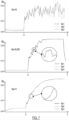
- THE figures 7 , 7A And 8 illustrate the various contributions provided by the implementation of the invention and the impact of the choice of the value of the correction coefficient Kc on the behavior of a control system in accordance with the invention.
- the two figures 7 And 8 respectively illustrate two quantities G in this case the components relating to the pitch ⁇ p, to the roll ⁇ r of the control ⁇ , and more particularly, the components of these quantities reflecting the integral action of a PID regulator of an angular speed controller 35 according to the figure 4 .
- the said figure 7 illustrates the respective productions over time t of said flight controllers FC-1, FC-2 and FC-3 according to three distinct values of the correction coefficient Kc, respectively equal to zero, five hundredths and one via three distinct graphs.
- an angle ⁇ 1 determined by the tangents tg0 and tg1, of low value reflects a slight drop in reactivity.
- the tangent tg2, shown in a dashed line, illustrates the reactivity of the control system during strong coupling (Kc 1).
- the angle ⁇ 2 determined by the tangents tg0 and tg2 is much greater than the angle ⁇ 1, indicating a lower reactivity.
- the said Figure 7A illustrates however the contribution in stability in return for a possibly reduced reactivity.
- the said figure 8 illustrates the respective productions of said flight controllers FC-1, FC-2 and FC-3, over time t, according to three distinct values of the correction coefficient Kc respectively equal to zero, five hundredths and one by means of three distinct graphs present respectively in the upper, central and lower parts of said figure 8 .
- the upper graph corresponds to a zero value of the correction coefficient Kc, i.e. a situation in accordance with the state of the art (no correction of the respective productions of the flight controllers FC-1, FC-2 and FC-3 is implemented).
- the central graph corresponds to a value of the correction coefficient Kc equal to five hundredths, i.e. a partial coupling of the respective productions of the flight controllers FC-1, FC-2 and FC-3.
- the lower graph corresponds to a value of the correction coefficient Kc equal to one, i.e. a total coupling of the respective productions of said flight controllers FC-1, FC-2 and FC-3.
- the servo devices in this case the PID regulators of the angular rate controllers 35 of the flight controllers FC-1, FC-2 and FC-3, are not coupled.
- the three curves ⁇ r1, ⁇ r2 and ⁇ r3 describing their respective productions show an increasing divergence and very marked oscillations.
- the implementation of the invention shows an immediate coupling as soon as the correction coefficient Kc is greater than zero.
- a very low value, five hundredths according to the example illustrated by the central graph of the figure 8 causes an almost perfect superposition of the three curves ⁇ r1, ⁇ r2 and ⁇ r3.
- the slope of the curves ⁇ r1, ⁇ r2 and ⁇ r3 is very steep or vertical at an instant tj for which the system responds to an instruction likely to cause a marked inflection of the value of said components ⁇ r1, ⁇ r2 and ⁇ r3.
- Such a slope is however less vertical, if we consider the values of said components ⁇ r1, ⁇ r2 and ⁇ r3 induced by a higher value of the correction coefficient Kc (value equal to one, in this case for the lower graph of the figure 8 ).
- the said superimposed curves are smoother or more stable than those represented on the central graph. This figure 8 confirms that the choice of the correction coefficient value Kc thus makes it possible to determine the compromise between the desired reactivity and stability of the system.
- the invention has been described through different configurations of an actuator control system, more precisely of thrust groups of an aircraft.
- the invention cannot be limited to this single example of an actuator control system. It relates more generally to any control system comprising one or more multiple redundancy servo devices applied to home automation, industry, land, sea, air or space vehicles, that said actuators allow to move the latter or to regulate the temperature, the atmosphere or even the brightness prevailing within the latter.
Landscapes
- Engineering & Computer Science (AREA)
- Physics & Mathematics (AREA)
- General Physics & Mathematics (AREA)
- Automation & Control Theory (AREA)
- Aviation & Aerospace Engineering (AREA)
- Feedback Control In General (AREA)
- Safety Devices In Control Systems (AREA)
Claims (16)
- Verfahren (100), durchgeführt von einer Verarbeitungseinheit eines Servogeräts unter mehreren redundanten Servogeräten (FC-1, FC-2, FC-3) eines Systems (30) zur Steuerung eines Aktuators (TS), wobei jedes redundante Servogerät Werte einer gleichen Größe (G) auf der Basis eines gleichen Sollwerts (Gsp) und eines gleichen Messdatenelements (Gs) erzeugt, wobei die genannten erzeugten Werte von dem genannten System (30) zum Steuern des Aktuators (TS) ausgewertet werden, wobei die genannten redundanten Servogeräte (FC-1, FC-2, FC-3) außerdem miteinander in Kommunikation stehen, so dass jedes redundante Servogerät lesend auf die letzten durch die genannten redundanten Servogeräte erzeugten Werte der genannten Größe (G) zugreift, wobei das genannte Verfahren iterativ Folgendes beinhaltet (SP):- einen Schritt (110) des Erzeugens des aktuellen Werts (GI) der Größe (G) auf der Basis des Sollwerts (Gsp) und des Messdatenelements (Gs);- einen Schritt (120) des Lesens der letzten durch die redundanten Servogeräte erzeugten Werte der Größe (G) und des Bildens eines Satzes (
G ) von aktuellen Werten der genannten Größe (G);- einen Schritt (130) des Bestimmens eines Referenzwerts (Gr) der genannten Größe (G), der aus dem genannten Satz (G ) entnommen wird;- einen Schritt (140) des Berechnens einer Abweichung (Ge) zwischen dem aktuellen Wert (Gl) der erzeugten Größe (G) und dem genannten Referenzwert (Gr);- einen Schritt (150) des Korrigierens des aktuellen Werts (Gl) und des Erzeugens eines korrigierten aktuellen Werts (GI') der Größe (G), der darin besteht, von dem genannten aktuellen Wert (GI) einen Korrekturwert (Gc) abzuziehen, der sich aus einer Berechnung ergibt, gemäß der die genannte Abweichung (Ge) mit einem Korrekturkoeffizienten (Kc) größer als Null des genannten aktuellen Werts (GI) multipliziert wird. - Verfahren (100) nach dem vorherigen Anspruch, wobei:- das System mindestens drei redundante Servogeräte mit der Fähigkeit umfasst, einen Wert der Größe (G) zu erzeugen;- der Schritt (130) des Bestimmens des Referenzwerts (Gr) darin besteht, den Median der Werte des Satzes (
G ) der aktuellen Werte der Größe (G) auszuwählen. - Verfahren (100) nach Anspruch 1, wobei:- das System nur zwei redundante Servogeräte mit der Fähigkeit umfasst, einen Wert der Größe (G) zu erzeugen;- der Schritt (130) des Bestimmens des Referenzwerts (Gr) darin besteht, einen der Werte aus dem Satz (
G ) der aktuellen Werte der Größe (G) auszuwählen. - Verfahren (100) nach einem der vorherigen Ansprüche, wobei der Wert des Korrekturkoeffizienten (Kc) vorbestimmt ist.
- Verfahren (100) nach einem der Ansprüche 1 bis 3, das einen Schritt (151) des Speicherns des aktuellen (Gl) oder korrigierten (GI') Werts der Größe (G) in einem Datenspeicher (M) des ersten Servogeräts zum Bilden einer Historie einer bestimmten Anzahl von Werten und vor dem Korrekturschritt (150) einen Schritt (101) des Erzeugens des Werts des Korrekturkoeffizienten (Kc) beinhaltet, der eine Funktion der Variabilität der aus der genannten Historie gezogenen Werte und der Iterationsfrequenz (SP) des Schrittes (120) des Lesens der letzten durch die redundanten Servogeräte erzeugten Werte der Größe (G) ist.
- Verfahren (100) nach einem der vorherigen Ansprüche, wobei das Berechnen des Korrekturwerts (Gc) so ausgelegt ist, dass der genannte Korrekturwert (Gc) einen vorbestimmten Grenzwert (L) in absoluten Zahlen nicht überschreitet.
- Verfahren (100) nach einem der vorherigen Ansprüche, wobei die redundanten Servogeräte jeweils einen PID-Korrektor umfassen, der drei Komponenten eines Ausgangssignals liefert, die jeweils eine Proportionalaktion, eine Integralaktion und eine Differentialaktion beschreiben, und wobei die Größe (G) aus der Komponente besteht, die die genannte Integralaktion des genannten PID-Korrektors beschreibt.
- Verfahren (100) nach einem der vorherigen Ansprüche, wenn das Steuersystem (30) redundante Quellen umfasst, die zum gemeinsamen Liefern einer Mehrzahl von Sollwerten (
Gsp ) ausgelegt sind, mit einem Schritt (102) des Erzeugens des genannten Sollwerts (Gsp), so dass dieser als Wert:- einen der Werte aus der genannten Mehrzahl von Werten (Gsp ) annimmt, wenn das Steuersystem (30) nur zwei redundante Quellen umfasst;- den Median der genannten Mehrzahl von Werten (Gsp ) annimmt, wenn das genannte Steuersystem mindestens drei redundante Quellen umfasst. - Verfahren (100) nach einem der vorherigen Ansprüche, wenn das Steuersystem (30) redundante Quellen umfasst, die zum gemeinsamen Liefern einer Mehrzahl von Werten des Messdatenelements (
Gs ) ausgelegt sind, mit einem Schritt (103) des Erzeugens des genannten Messdatenelements (Gs), so dass dieses (Gs) als Wert:- einen der Werte aus der genannten Mehrzahl von Werten (Gs ) annimmt, wenn das Steuersystem nur zwei redundante Quellen umfasst;- den Median der genannten Mehrzahl von Werten (Gs ) annimmt, wenn das Steuersystem mindestens drei redundante Quellen umfasst. - Servogerät eines Systems (30) zum Steuern eines Aktuators (TS), wobei das genannte System (30) eine Mehrzahl von redundanten Servogeräten (FC-1, FC-2, FC-3) umfasst, die jeweils einen Wert (Δ1, Δ2, Δ3) einer gleichen Größe auf der Basis eines gleichen Sollwerts (Gsp,
Gsp ) und eines gleichen Messdatenelements (Gs1, Gs2, Gs3) erzeugen, wobei die genannten redundanten Servogeräte (FC-1, FC-2, FC-3) miteinander in Kommunikation stehen (B), so dass jedes Servogerät lesend auf die letzten durch die redundanten Servogeräte erzeugten Werte (Δ1, Δ2, Δ3) der genannten Größe zugreift, wobei das genannte Servogerät (FC-1, FC-2, FC-3) zum Durchführen eines Verfahrens (100) nach einem der vorherigen Ansprüche ausgelegt ist. - System (30) zum Steuern eines Aktuators (TS) mit einer Mehrzahl von redundanten Servogeräten (FC-1, FC-2, FC-3) nach dem vorherigen Anspruch, wobei der genannte Steuerbefehl (
Δ , Δ) auf der Basis der Mehrzahl von gemeinsam durch die redundanten Servogeräte erzeugten Werten (Δ1, Δ2, Δ3) der Größe erzeugt wird. - System (30) nach dem vorherigen Anspruch, wobei der genannte Steuerbefehl (Δ) erzeugt wird auf der Basis von:- einem der Werte aus der genannten Mehrzahl von durch die redundanten Servogeräte erzeugten Werten (
Δ , Δ1, Δ2, Δ3) der Größe, wenn die genannte Mehrzahl von Werten (, Δ1, Δ2, Δ3) nur zwei Werte umfasst;- dem Median der genannten Mehrzahl von durch die redundanten Servogeräte erzeugten Werten (Δ , Δ1, Δ2, Δ3) der Größe, wenn die genannte Mehrzahl von Werten (Δ , Δ1, Δ2, Δ3) mindestens drei Werte umfasst. - Fahrzeug (10) für eine aus einem Fahrer, einem Passagier und/oder Gütern oder Waren bestehende Ladung mit einem oder mehreren Aktuatoren in Form von mindestens einer Schubeinheit (TSa, TSb, TSc, TSd) zum Bewegen des genannten Fahrzeugs (10), für das ein Steuerbefehl (
Δ , Δ) durch ein Steuersystem (30) nach dem vorherigen Anspruch erzeugt wird. - Fahrzeug (10) nach dem vorherigen Anspruch, das aus einem Luftfahrzeug (10) besteht.
- Computerprogrammprodukt, das einen oder mehrere Programmbefehle umfasst, die von einer Verarbeitungseinheit (Ut) eines Servogeräts aus einer Mehrzahl von redundanten Servogeräten (FC-1, FC-2, FC-3) eines Systems (30) zum Steuern eines Aktuators (TS) interpretierbar sind, wobei die genannten Programmbefehle in einen nichtflüchtigen Speicher (M) des Servogeräts ladbar und so ausgelegt sind, dass die Ausführung der genannten Befehle durch die genannte Verarbeitungseinheit (Ut) die Durchführung eines Verfahrens (100) nach einem der Ansprüche 1 bis 9 bewirkt.
- Computerlesbares Speichermedium mit den Befehlen eines Computerprogrammprodukts nach dem vorherigen Anspruch.
Applications Claiming Priority (2)
| Application Number | Priority Date | Filing Date | Title |
|---|---|---|---|
| FR2209922A FR3140348B1 (fr) | 2022-09-29 | 2022-09-29 | Procédé de couplage pour dispositifs d’asservissement redondants d’un système de commande d’un actionneur, système et dispositif associés |
| PCT/FR2023/051476 WO2024069093A1 (fr) | 2022-09-29 | 2023-09-26 | Procédé de couplage pour dispositifs d'asservissement redondants d'un système de commande d'un actionneur, système et dispositif associés |
Publications (2)
| Publication Number | Publication Date |
|---|---|
| EP4437385A1 EP4437385A1 (de) | 2024-10-02 |
| EP4437385B1 true EP4437385B1 (de) | 2025-02-26 |
Family
ID=85018223
Family Applications (1)
| Application Number | Title | Priority Date | Filing Date |
|---|---|---|---|
| EP23786641.3A Active EP4437385B1 (de) | 2022-09-29 | 2023-09-26 | Kopplungsverfahren für redundante servovorrichtungen eines aktuatorsteuerungssystems, zugehöriges system und vorrichtung |
Country Status (12)
| Country | Link |
|---|---|
| US (1) | US12371155B2 (de) |
| EP (1) | EP4437385B1 (de) |
| JP (1) | JP2025536132A (de) |
| CN (1) | CN118974666A (de) |
| AU (1) | AU2023348067B2 (de) |
| CA (1) | CA3266367A1 (de) |
| ES (1) | ES3031887T3 (de) |
| FR (1) | FR3140348B1 (de) |
| IL (1) | IL319727A (de) |
| PL (1) | PL4437385T3 (de) |
| PT (1) | PT4437385T (de) |
| WO (1) | WO2024069093A1 (de) |
Family Cites Families (10)
| Publication number | Priority date | Publication date | Assignee | Title |
|---|---|---|---|---|
| CA2137157A1 (en) | 1992-06-12 | 1993-12-23 | Edward R. Sederlund | Stealth interface for process control computers |
| JPH06324702A (ja) * | 1993-05-17 | 1994-11-25 | Toshiba Corp | 制御システム |
| DE10032179A1 (de) * | 2000-07-01 | 2002-01-17 | Daimler Chrysler Ag | Steuerungssystem für ein Fahrzeug und Verfahren zur Steuerung eines Fahrzeugs |
| JP2002021341A (ja) * | 2000-07-06 | 2002-01-23 | Misawa Homes Co Ltd | ガレージを備えた住宅 |
| US7181644B2 (en) * | 2002-01-11 | 2007-02-20 | Delphi Technologies, Inc. | Method for synchronizing data utilized in redundant, closed loop control systems |
| CA2595256C (en) * | 2005-02-11 | 2009-12-29 | Bell Helicopter Textron Inc. | Dual motor dual concentric valve |
| DE102008024180A1 (de) * | 2007-06-19 | 2008-12-24 | Continental Teves Ag & Co. Ohg | Kombinierte Bremsanlage, insbesondere für Kraftfahrzeuge |
| WO2018118070A1 (en) * | 2016-12-22 | 2018-06-28 | Kitty Hawk Corporation | Distributed flight control system |
| EP3495262B1 (de) | 2017-12-07 | 2023-09-27 | Zipair | Antriebsvorrichtung mit einer plattform zum unterstützen eines fluggasts |
| GB2586055A (en) * | 2019-07-31 | 2021-02-03 | Airbus Operations Ltd | Aircraft brake control system |
-
2022
- 2022-09-29 FR FR2209922A patent/FR3140348B1/fr active Active
-
2023
- 2023-09-26 AU AU2023348067A patent/AU2023348067B2/en active Active
- 2023-09-26 US US18/837,502 patent/US12371155B2/en active Active
- 2023-09-26 JP JP2025518286A patent/JP2025536132A/ja active Pending
- 2023-09-26 WO PCT/FR2023/051476 patent/WO2024069093A1/fr not_active Ceased
- 2023-09-26 IL IL319727A patent/IL319727A/en unknown
- 2023-09-26 CA CA3266367A patent/CA3266367A1/fr active Pending
- 2023-09-26 PL PL23786641.3T patent/PL4437385T3/pl unknown
- 2023-09-26 PT PT237866413T patent/PT4437385T/pt unknown
- 2023-09-26 CN CN202380032475.6A patent/CN118974666A/zh active Pending
- 2023-09-26 ES ES23786641T patent/ES3031887T3/es active Active
- 2023-09-26 EP EP23786641.3A patent/EP4437385B1/de active Active
Also Published As
| Publication number | Publication date |
|---|---|
| ES3031887T3 (en) | 2025-07-11 |
| JP2025536132A (ja) | 2025-10-31 |
| US20250108912A1 (en) | 2025-04-03 |
| IL319727A (en) | 2025-05-01 |
| US12371155B2 (en) | 2025-07-29 |
| AU2023348067A1 (en) | 2025-04-03 |
| EP4437385A1 (de) | 2024-10-02 |
| CN118974666A (zh) | 2024-11-15 |
| PL4437385T3 (pl) | 2025-06-23 |
| AU2023348067B2 (en) | 2025-07-03 |
| CA3266367A1 (fr) | 2024-04-04 |
| PT4437385T (pt) | 2025-05-19 |
| FR3140348B1 (fr) | 2025-06-27 |
| FR3140348A1 (fr) | 2024-04-05 |
| WO2024069093A1 (fr) | 2024-04-04 |
Similar Documents
| Publication | Publication Date | Title |
|---|---|---|
| EP0296951B1 (de) | Roll- und Giersteuerungssystem für ein Luftfahrzeug | |
| CA2055089C (fr) | Systeme pour la commande integree en profondeur et en poussee d'un aeronef | |
| EP3035143B1 (de) | Verfahren und system zur bestimmung eines sollwerts für die winkelgeschwindigkeit beim kurvenfliegen für ein drehflügelflugzeug | |
| WO2019238375A1 (fr) | Système et procédé de contrôle de vol d'un drone convertible à voilure fixe permettant une transition continue stabilisée entre un vol stationnaire vertical et un vol de croisière à l'horizontal | |
| FR2959205A1 (fr) | Procede de commande et de regulation de l'angle de braquage d'un empennage d'helicoptere hybride | |
| FR2689854A1 (fr) | Hélicoptère monorotor à système anticouple mixte et procédé pour contrecarrer le couple induit par ce monorotor. | |
| FR3024867A1 (fr) | Systeme de commande d'organe de commande dans des systemes aeronautiques de commande de vol electrique | |
| EP2963517B1 (de) | System und verfahren für die flugsteuerung eines drehflügelflugzeugs mit beibehaltung der flugbahn oder des kurses je nach vorschubgeschwindigkeit | |
| EP3264214A1 (de) | Verfahren zur dynamischen fluglage-konvertierung eines drehflügeldrohne | |
| CA2895081C (fr) | Procede et systeme de mise en vol stationnaire d'un aeronef a voilure tournante en tenue de trajectoire ou tenue de cap selon sa vitesse d'avancement | |
| FR2920129A1 (fr) | Procede et systeme de manoeuvre d'un aeronef par deplacement de son centre de gravite | |
| FR3054900A1 (fr) | Commande de la décharge de gouverne de profondeur vers le stabilisateur dans les système d'aéronef à vol électrique | |
| EP3260945A1 (de) | Drohne mit tragflügeln | |
| FR3036805A1 (fr) | Procede de determination de la vitesse air longitudinale et de la vitesse sol longitudinale d'un aeronef a voiture tournante selon son exposition au vent | |
| EP1989104B1 (de) | Elektrisches steuersystem für eine flugzeuglenkschaufel | |
| EP4437385B1 (de) | Kopplungsverfahren für redundante servovorrichtungen eines aktuatorsteuerungssystems, zugehöriges system und vorrichtung | |
| FR2927428A1 (fr) | Procede et dispositif pour attenuer les effets d'une turbulence verticale sur un aeronef | |
| EP3034394B1 (de) | Verfahren zur handhabung von diskontinuitäten in einer fahrzeugsteuerung infolge einer umschaltung der steuerung, und entsprechendes fahrzeug | |
| FR3032551A1 (fr) | Systeme et procede de pilotage d'un aeronef. | |
| CN113492971B (zh) | 飞行装置及其控制方法和控制装置 | |
| FR2909463A1 (fr) | Procede et dispositif de controle actif du roulis d'un avion | |
| FR2914074A1 (fr) | Methode de generation de valeurs de consignes servant a asservir un parametre de vol p d'un aeronef equipe d'un pilote automatique. | |
| WO2025219681A1 (fr) | Aéronef à système de gestion du lacet et procédé de gestion du lacet | |
| HK40119197A (zh) | 用於致动器操纵系统的冗余伺服装置的耦合方法、相关系统和装置 | |
| FR3110545A1 (fr) | Procédé d’optimisation d’une consommation d’énergie d’un hélicoptère hybride en vol en palier |
Legal Events
| Date | Code | Title | Description |
|---|---|---|---|
| STAA | Information on the status of an ep patent application or granted ep patent |
Free format text: STATUS: UNKNOWN |
|
| STAA | Information on the status of an ep patent application or granted ep patent |
Free format text: STATUS: THE INTERNATIONAL PUBLICATION HAS BEEN MADE |
|
| PUAI | Public reference made under article 153(3) epc to a published international application that has entered the european phase |
Free format text: ORIGINAL CODE: 0009012 |
|
| STAA | Information on the status of an ep patent application or granted ep patent |
Free format text: STATUS: REQUEST FOR EXAMINATION WAS MADE |
|
| 17P | Request for examination filed |
Effective date: 20240627 |
|
| AK | Designated contracting states |
Kind code of ref document: A1 Designated state(s): AL AT BE BG CH CY CZ DE DK EE ES FI FR GB GR HR HU IE IS IT LI LT LU LV MC ME MK MT NL NO PL PT RO RS SE SI SK SM TR |
|
| GRAP | Despatch of communication of intention to grant a patent |
Free format text: ORIGINAL CODE: EPIDOSNIGR1 |
|
| STAA | Information on the status of an ep patent application or granted ep patent |
Free format text: STATUS: GRANT OF PATENT IS INTENDED |
|
| INTG | Intention to grant announced |
Effective date: 20241010 |
|
| GRAS | Grant fee paid |
Free format text: ORIGINAL CODE: EPIDOSNIGR3 |
|
| GRAA | (expected) grant |
Free format text: ORIGINAL CODE: 0009210 |
|
| STAA | Information on the status of an ep patent application or granted ep patent |
Free format text: STATUS: THE PATENT HAS BEEN GRANTED |
|
| AK | Designated contracting states |
Kind code of ref document: B1 Designated state(s): AL AT BE BG CH CY CZ DE DK EE ES FI FR GB GR HR HU IE IS IT LI LT LU LV MC ME MK MT NL NO PL PT RO RS SE SI SK SM TR |
|
| DAV | Request for validation of the european patent (deleted) | ||
| DAX | Request for extension of the european patent (deleted) | ||
| REG | Reference to a national code |
Ref country code: GB Ref legal event code: FG4D Free format text: NOT ENGLISH |
|
| REG | Reference to a national code |
Ref country code: CH Ref legal event code: EP |
|
| P01 | Opt-out of the competence of the unified patent court (upc) registered |
Free format text: CASE NUMBER: APP_4040/2025 Effective date: 20250124 |
|
| REG | Reference to a national code |
Ref country code: DE Ref legal event code: R096 Ref document number: 602023002229 Country of ref document: DE |
|
| REG | Reference to a national code |
Ref country code: IE Ref legal event code: FG4D Free format text: LANGUAGE OF EP DOCUMENT: FRENCH |
|
| REG | Reference to a national code |
Ref country code: PT Ref legal event code: SC4A Ref document number: 4437385 Country of ref document: PT Date of ref document: 20250519 Kind code of ref document: T Free format text: AVAILABILITY OF NATIONAL TRANSLATION Effective date: 20250512 |
|
| REG | Reference to a national code |
Ref country code: NL Ref legal event code: FP |
|
| PG25 | Lapsed in a contracting state [announced via postgrant information from national office to epo] |
Ref country code: RS Free format text: LAPSE BECAUSE OF FAILURE TO SUBMIT A TRANSLATION OF THE DESCRIPTION OR TO PAY THE FEE WITHIN THE PRESCRIBED TIME-LIMIT Effective date: 20250526 |
|
| PG25 | Lapsed in a contracting state [announced via postgrant information from national office to epo] |
Ref country code: FI Free format text: LAPSE BECAUSE OF FAILURE TO SUBMIT A TRANSLATION OF THE DESCRIPTION OR TO PAY THE FEE WITHIN THE PRESCRIBED TIME-LIMIT Effective date: 20250226 |
|
| REG | Reference to a national code |
Ref country code: LT Ref legal event code: MG9D |
|
| REG | Reference to a national code |
Ref country code: ES Ref legal event code: FG2A Ref document number: 3031887 Country of ref document: ES Kind code of ref document: T3 Effective date: 20250711 |
|
| PG25 | Lapsed in a contracting state [announced via postgrant information from national office to epo] |
Ref country code: IS Free format text: LAPSE BECAUSE OF FAILURE TO SUBMIT A TRANSLATION OF THE DESCRIPTION OR TO PAY THE FEE WITHIN THE PRESCRIBED TIME-LIMIT Effective date: 20250626 Ref country code: NO Free format text: LAPSE BECAUSE OF FAILURE TO SUBMIT A TRANSLATION OF THE DESCRIPTION OR TO PAY THE FEE WITHIN THE PRESCRIBED TIME-LIMIT Effective date: 20250526 |
|
| PG25 | Lapsed in a contracting state [announced via postgrant information from national office to epo] |
Ref country code: HR Free format text: LAPSE BECAUSE OF FAILURE TO SUBMIT A TRANSLATION OF THE DESCRIPTION OR TO PAY THE FEE WITHIN THE PRESCRIBED TIME-LIMIT Effective date: 20250226 |
|
| PG25 | Lapsed in a contracting state [announced via postgrant information from national office to epo] |
Ref country code: LV Free format text: LAPSE BECAUSE OF FAILURE TO SUBMIT A TRANSLATION OF THE DESCRIPTION OR TO PAY THE FEE WITHIN THE PRESCRIBED TIME-LIMIT Effective date: 20250226 |
|
| PG25 | Lapsed in a contracting state [announced via postgrant information from national office to epo] |
Ref country code: BG Free format text: LAPSE BECAUSE OF FAILURE TO SUBMIT A TRANSLATION OF THE DESCRIPTION OR TO PAY THE FEE WITHIN THE PRESCRIBED TIME-LIMIT Effective date: 20250226 Ref country code: GR Free format text: LAPSE BECAUSE OF FAILURE TO SUBMIT A TRANSLATION OF THE DESCRIPTION OR TO PAY THE FEE WITHIN THE PRESCRIBED TIME-LIMIT Effective date: 20250527 |
|
| PG25 | Lapsed in a contracting state [announced via postgrant information from national office to epo] |
Ref country code: SE Free format text: LAPSE BECAUSE OF FAILURE TO SUBMIT A TRANSLATION OF THE DESCRIPTION OR TO PAY THE FEE WITHIN THE PRESCRIBED TIME-LIMIT Effective date: 20250226 |
|
| PGFP | Annual fee paid to national office [announced via postgrant information from national office to epo] |
Ref country code: LU Payment date: 20250820 Year of fee payment: 3 |
|
| PG25 | Lapsed in a contracting state [announced via postgrant information from national office to epo] |
Ref country code: SM Free format text: LAPSE BECAUSE OF FAILURE TO SUBMIT A TRANSLATION OF THE DESCRIPTION OR TO PAY THE FEE WITHIN THE PRESCRIBED TIME-LIMIT Effective date: 20250226 |
|
| PGFP | Annual fee paid to national office [announced via postgrant information from national office to epo] |
Ref country code: PT Payment date: 20250826 Year of fee payment: 3 |
|
| PG25 | Lapsed in a contracting state [announced via postgrant information from national office to epo] |
Ref country code: DK Free format text: LAPSE BECAUSE OF FAILURE TO SUBMIT A TRANSLATION OF THE DESCRIPTION OR TO PAY THE FEE WITHIN THE PRESCRIBED TIME-LIMIT Effective date: 20250226 |
|
| PGFP | Annual fee paid to national office [announced via postgrant information from national office to epo] |
Ref country code: DE Payment date: 20250820 Year of fee payment: 3 |
|
| PGFP | Annual fee paid to national office [announced via postgrant information from national office to epo] |
Ref country code: MC Payment date: 20250826 Year of fee payment: 3 |
|
| PGFP | Annual fee paid to national office [announced via postgrant information from national office to epo] |
Ref country code: PL Payment date: 20250824 Year of fee payment: 3 Ref country code: TR Payment date: 20250902 Year of fee payment: 3 |
|
| PGFP | Annual fee paid to national office [announced via postgrant information from national office to epo] |
Ref country code: BE Payment date: 20250820 Year of fee payment: 3 |
|
| PGFP | Annual fee paid to national office [announced via postgrant information from national office to epo] |
Ref country code: FR Payment date: 20250820 Year of fee payment: 3 Ref country code: AT Payment date: 20251020 Year of fee payment: 3 |
|
| PG25 | Lapsed in a contracting state [announced via postgrant information from national office to epo] |
Ref country code: EE Free format text: LAPSE BECAUSE OF FAILURE TO SUBMIT A TRANSLATION OF THE DESCRIPTION OR TO PAY THE FEE WITHIN THE PRESCRIBED TIME-LIMIT Effective date: 20250226 Ref country code: CZ Free format text: LAPSE BECAUSE OF FAILURE TO SUBMIT A TRANSLATION OF THE DESCRIPTION OR TO PAY THE FEE WITHIN THE PRESCRIBED TIME-LIMIT Effective date: 20250226 |
|
| PGFP | Annual fee paid to national office [announced via postgrant information from national office to epo] |
Ref country code: IE Payment date: 20250822 Year of fee payment: 3 |
|
| PG25 | Lapsed in a contracting state [announced via postgrant information from national office to epo] |
Ref country code: SK Free format text: LAPSE BECAUSE OF FAILURE TO SUBMIT A TRANSLATION OF THE DESCRIPTION OR TO PAY THE FEE WITHIN THE PRESCRIBED TIME-LIMIT Effective date: 20250226 |
|
| REG | Reference to a national code |
Ref country code: DE Ref legal event code: R097 Ref document number: 602023002229 Country of ref document: DE |
|
| PLBE | No opposition filed within time limit |
Free format text: ORIGINAL CODE: 0009261 |
|
| STAA | Information on the status of an ep patent application or granted ep patent |
Free format text: STATUS: NO OPPOSITION FILED WITHIN TIME LIMIT |
|
| PGFP | Annual fee paid to national office [announced via postgrant information from national office to epo] |
Ref country code: IT Payment date: 20250930 Year of fee payment: 3 |
|
| PGFP | Annual fee paid to national office [announced via postgrant information from national office to epo] |
Ref country code: ES Payment date: 20251001 Year of fee payment: 3 |
|
| 26N | No opposition filed |
Effective date: 20251127 |
|
| PG25 | Lapsed in a contracting state [announced via postgrant information from national office to epo] |
Ref country code: RO Free format text: LAPSE BECAUSE OF FAILURE TO SUBMIT A TRANSLATION OF THE DESCRIPTION OR TO PAY THE FEE WITHIN THE PRESCRIBED TIME-LIMIT Effective date: 20250226 |