EP4438418A1 - Seitenairbag - Google Patents
Seitenairbag Download PDFInfo
- Publication number
- EP4438418A1 EP4438418A1 EP23165626.5A EP23165626A EP4438418A1 EP 4438418 A1 EP4438418 A1 EP 4438418A1 EP 23165626 A EP23165626 A EP 23165626A EP 4438418 A1 EP4438418 A1 EP 4438418A1
- Authority
- EP
- European Patent Office
- Prior art keywords
- bag
- air
- fabric
- layer
- vehicle
- Prior art date
- Legal status (The legal status is an assumption and is not a legal conclusion. Google has not performed a legal analysis and makes no representation as to the accuracy of the status listed.)
- Pending
Links
Images




Classifications
-
- B—PERFORMING OPERATIONS; TRANSPORTING
- B60—VEHICLES IN GENERAL
- B60R—VEHICLES, VEHICLE FITTINGS, OR VEHICLE PARTS, NOT OTHERWISE PROVIDED FOR
- B60R21/00—Arrangements or fittings on vehicles for protecting or preventing injuries to occupants or pedestrians in case of accidents or other traffic risks
- B60R21/02—Occupant safety arrangements or fittings, e.g. crash pads
- B60R21/16—Inflatable occupant restraints or confinements designed to inflate upon impact or impending impact, e.g. air bags
- B60R21/23—Inflatable members
- B60R21/237—Inflatable members characterised by the way they are folded
-
- B—PERFORMING OPERATIONS; TRANSPORTING
- B60—VEHICLES IN GENERAL
- B60R—VEHICLES, VEHICLE FITTINGS, OR VEHICLE PARTS, NOT OTHERWISE PROVIDED FOR
- B60R21/00—Arrangements or fittings on vehicles for protecting or preventing injuries to occupants or pedestrians in case of accidents or other traffic risks
- B60R21/02—Occupant safety arrangements or fittings, e.g. crash pads
- B60R21/16—Inflatable occupant restraints or confinements designed to inflate upon impact or impending impact, e.g. air bags
- B60R21/20—Arrangements for storing inflatable members in their non-use or deflated condition; Arrangement or mounting of air bag modules or components
- B60R21/21—Arrangements for storing inflatable members in their non-use or deflated condition; Arrangement or mounting of air bag modules or components in vehicle side panels, e.g. doors
-
- B—PERFORMING OPERATIONS; TRANSPORTING
- B60—VEHICLES IN GENERAL
- B60R—VEHICLES, VEHICLE FITTINGS, OR VEHICLE PARTS, NOT OTHERWISE PROVIDED FOR
- B60R21/00—Arrangements or fittings on vehicles for protecting or preventing injuries to occupants or pedestrians in case of accidents or other traffic risks
- B60R21/02—Occupant safety arrangements or fittings, e.g. crash pads
- B60R21/16—Inflatable occupant restraints or confinements designed to inflate upon impact or impending impact, e.g. air bags
- B60R21/23—Inflatable members
- B60R21/231—Inflatable members characterised by their shape, construction or spatial configuration
- B60R21/23138—Inflatable members characterised by their shape, construction or spatial configuration specially adapted for side protection
-
- B—PERFORMING OPERATIONS; TRANSPORTING
- B60—VEHICLES IN GENERAL
- B60R—VEHICLES, VEHICLE FITTINGS, OR VEHICLE PARTS, NOT OTHERWISE PROVIDED FOR
- B60R21/00—Arrangements or fittings on vehicles for protecting or preventing injuries to occupants or pedestrians in case of accidents or other traffic risks
- B60R21/02—Occupant safety arrangements or fittings, e.g. crash pads
- B60R21/16—Inflatable occupant restraints or confinements designed to inflate upon impact or impending impact, e.g. air bags
- B60R21/23—Inflatable members
- B60R21/231—Inflatable members characterised by their shape, construction or spatial configuration
- B60R21/23138—Inflatable members characterised by their shape, construction or spatial configuration specially adapted for side protection
- B60R2021/23146—Inflatable members characterised by their shape, construction or spatial configuration specially adapted for side protection seat mounted
Definitions
- the present invention relates to a side air-bag for a motor vehicle.
- the present invention more particularly relates to a side air-bag to protect an occupant of a vehicle in the event of a crash situation.
- a side air-bag is a type of safety device that is mounted within a vehicle to protect an occupant of the vehicle in the event of a crash situation.
- a side air-bag is particularly beneficial in protecting an occupant of a vehicle in the event that the vehicle is involved in a side impact.
- Figure 1 of the accompanying drawings shows a front view of an occupant 1 of a vehicle and a conventional side air-bag 2 in an inflated configuration, after having been deployed.
- Figure 2 shows a top view of the occupant 1 and the air-bag 2 of Figure 1 .
- the inflated air-bag 2 is positioned between a door 3 of the vehicle and the occupant 1.
- the air-bag 2 acts as a cushion that restricts movement of the occupant 1 relative to the door 3.
- the air-bag 2 dissipates kinetic energy of the occupant 1 to minimise the risk of the occupant 1 striking the door 3 and being injured during the crash situation.
- a problem with side air-bags such as the air-bag 2 shown in Figures 1 and 2 , is that the air-bag 2 typically does not contact the torso of the occupant 1 sufficiently. This can lead to high forces being exerted by the inflated air-bag 2 on an arm 4 and/or a shoulder 5 of the occupant 1, which can in turn cause injury to the arm 4 or shoulder 5.
- the conventional air-bag 2 can also lead to injury of the ribs of the occupant 1 due to the air-bag 2 transmitting a force that pushes the arm 4 of the occupant 1 against the ribs of the occupant 1.
- the present invention provides a side air-bag as claimed in claim 1 and a side air-bag module as claimed in claim 10.
- the present invention also provides preferred embodiments as claimed in the dependent claims.
- the air-bag of some examples of this disclosure fills the space between the door of a vehicle and the torso of an occupant of the vehicle fully, thereby stabilising and minimising movement of the occupant of the vehicle during a crash situation.
- the air-bag of some examples of this disclosure rotates the arm of an occupant during deployment which leads to more inboard positioning of the inflated air-bag relative to a conventional side air-bag. This further inboard positioning further enhances the protection to the vehicle occupant as compared with a conventional side air-bag.
- the air-bag of some examples of this disclosure can be configured easily to inflate in a desired manner for a particular vehicle type by changing the number of pleats and/or the position of the pleats in the air-bag. Such flexibility is not possible with standard conventional side air-bags that are not folded with pleats.
- the air-bag of some examples of this disclosure is provided with at least one pleat that unfolds as the air-bag inflates to increase the volume of the air-bag and fully fill the space on one side of an occupant of a vehicle.
- the air-bag of some examples of this disclosure avoids the need to add additional fabric and seams to increase the volume of the air-bag, which would otherwise increase the weight and packing size of the air-bag.
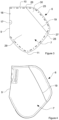
- a side air-bag 6 of an example of this disclosure comprises a first layer of fabric 7 and a second layer of fabric 8.
- the first and second layers of fabric 7, 8 are formed integrally with one another and folded along an axis of a fold line 9 so that the layers of fabric 7, 8 are superimposed on one another.
- the first and second layers of fabric 7, 8 are initially separate but joined to on another during the manufacturing process.
- the first and second layers of fabric 7, 8 are elongate in the sense that the first and second layers of fabric 7, 8 have a length which extends between a first end 10 and a second end 11 of the first layer of fabric 7 or between a first end 12 and a second end 13 of the second layer of fabric 8.
- the first ends 10, 12 are positioned at the top of the air-bag 6 and the second ends 11, 13 are positioned at the bottom of the air-bag 6 when the air-bag 6 is inflated within a vehicle.
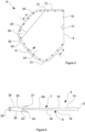
- the second layer of fabric 8 is superimposed on the first layer of fabric 7 to form a chamber 14 between a section 15 of the first layer of fabric 7 and a section 16 of the second layer of fabric 8, as shown in Figure 6 of the accompanying drawings.
- the air-bag 6 is provided with a gas inlet aperture 17 which, in this example, is positioned at the fold line 9 between the first and second layers of fabric 7, 8.
- the air-bag 6 is provided with a mounting aperture 18 in the vicinity of the gas inlet aperture 17 to receive a mounting element to mount a gas generator to the air-bag 6.
- the mounting aperture 18 is omitted.
- the first layer of fabric 7 is folded with at least one first elongate pleat 19.
- the first elongate pleat 19 is formed from a first fold 20 and a second fold 21, which together form a Z-fold in the first layer of fabric 7.
- the first layer of fabric 7 is folded with at least one first elongate pleat having a fold shape that is different from a Z-fold.
- the second layer of fabric 8 is folded with at least one second elongate pleat 22.
- the second elongate pleat 22 is formed from a first fold 23 and a second fold 24, which together form a Z-fold in the second layer of fabric 8.
- the second layer of fabric 8 is folded with at least one second elongate pleat having a fold shape that is different from a Z-fold.
- the first and second elongate pleats 19, 22 reduce the overall width of the first and second layers of fabric 7, 8 so that the first and second layers of fabric 7, 8 are the same or similar width to one another, as shown in Figures 3 and 4 . Therefore, when the first and second elongate pleats 19, 22 are folded, the first layer of fabric 7 sits generally flat when superimposed on the second layer of fabric 8.
- the first and second layers of fabric 7, 8 are superimposed on one another and the first and second layers of fabric 7, 8 are stitched together along a seam 25 that extends at least partly around periphery of the first layer of fabric 7 and the second layer of fabric 8.
- the seam 25 provides a gas tight or substantially gas tight seal that minimises or prevents gas from leaking out from the air-bag 6 upon inflation.
- the first elongate pleat 19 has a first end 26 and a second end 27.
- the first end 26 of the first elongate pleat 19 is positioned at the first end 10 of the first layer of fabric 7.
- the second end 27 of the first elongate pleat 19 intersects with an outer edge 28 of the first layer of fabric 7 which is remote from the fold line 9.
- the first elongate pleat 19 is at an oblique angle relative to the axis of the fold line 9.
- the first elongate pleat 19 extends across part of the width of the first layer of fabric 7 and divides the first layer of fabric 7 into a first area 29 and a second area 30, with the first area 29 being larger than the second area 30.
- the second elongate pleat 22 has a first end 31 and a second end 32.
- the first end 31 of the second elongate pleat 22 is positioned at the first end 12 of the second layer of fabric 8.
- the second end 32 of the second elongate pleat 22 intersects with an outer edge 33 of the second layer of fabric 8 which is remote from the fold line 9.
- the second elongate pleat 22 is at an oblique angle relative to the axis of the fold line 9.
- the second elongate pleat 22 extends across part of the width of the second layer of fabric 8 and divides the second layer of fabric 7 into a first area 34 and a second area 35, with the first area 34 being larger than the second area 35.
- first layer of fabric 7 and the second layer of fabric 8 are substantially symmetrical or symmetrical in shape about the axis of the fold line 9.
- first and second elongate pleats 19, 22 are positioned symmetrically about the axis of the fold line 9.
- the chamber 14 is at a first volume and the air-bag 6 is in a first configuration.
- the air-bag 6 is in the first configuration when the air-bag 6 is not inflated, for instance when the air-bag 6 is folded and packed within an enclosure.
- the first and second elongate pleats 19, 22 enable a second portion of the air-bag 6 to expand to a greater width than a first portion of the air-bag 6 as the air-bag 6 inflates and transitions between the first configuration and a second configuration.
- the first portion of the air-bag 6 is formed at least partly by the first area 29 of the first layer of fabric 7 and the first area 34 of the second layer of fabric 8.
- the second portion of the air-bag 6 is formed at least partly by the second area 30 of the first layer of fabric 7 and the second area 35 of the second layer of fabric 8.
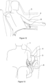
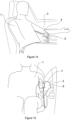
- the air-bag 6 expands to at least partly fill a space adjacent to the torso of the occupant 1, as shown in Figure 10 and 11 .
- the second portion of the air-bag 6 expands to present an activation surface 36 which exerts a biassing force on the underside of the arm 4 of the occupant 1.
- the biassing force rotates and lifts the arm 4 of the occupant 1 and the air-bag 6 inflates to fill the space adjacent the torso of the occupant 1.
- the air-bag is free to contact the torso of the occupant 1 and provide a cushion between the torso of the occupant and the door 3 of the vehicle.
- the inflated air-bag 6 is positioned symmetrically beneath the arm 4 of the occupant 1. The inflated air-bag 6 therefore has improved inboard positioning compared with a conventional side air-bag.
- the lifting effect moves the arm 4 of the occupant 1 out of the way so that the arm 4 is not pressed against the ribs of the occupant 1 by the inflated air-bag 6 due to forces arising during a crash situation. This also minimises transverse forces exerted on the arm 4 of the occupant 1 by the inflated air-bag 6 during a crash situation that might strain and injure the shoulder 5 of the occupant 1.
- the arm 4 of the occupant 1 is instead moved out of the way by the inflating air-bag 6 to enable the air-bag 6 to contact the torso of the occupant 1.
- the expansion of the air-bag 6 from the first volume to the second, greater, volume ensures that the air-bag 6 fills the space between the torso of the occupant 1 and the door 3 of the vehicle. This provides improved stabilisation that minimises movement of the occupant 1 relative to the door 3 and helps minimise injury to the occupant 1 during a crash situation.
- a first, or top, end of the air-bag 6 has a greater thickness than a second, or bottom, end of the air-bag 6 due to the unfolded pleats 19, 22 being positioned closer to the first, or top, end than the second, or bottom, end of the air-bag 6.
- the greater thickness of the first, or top, end of the air-bag 6 is appropriate to fill the space between the torso of the occupant 1 and the door 3 of the vehicle, as shown in Figure 10 .
- the narrower thickness second, or bottom, end of the air-bag 6 is appropriate to fill the smaller space between the leg of the occupant 1 and the door 3, which further stabilises the air-bag in position between the occupant 1 and the door 3.
- first elongate pleat 19 and one second elongate pleat 22 there is one first elongate pleat 19 and one second elongate pleat 22.
- at least one of the first layer of fabric 7 and the second layer of fabric 8 are provided with a plurality of spaced apart elongate pleats. The number of pleats may be selected to achieve a desired shape of the air-bag upon inflation to provide an appropriate restraint for an occupant of a vehicle.
- an air-bag of another example of this disclosure is a farside air-bag to be inflated centrally within a vehicle between two seats.
- the farside air-bag is of the same configuration and comprises the same elements as the other air-bags described above to ensure that the air-bag lifts the arms of occupants on one or both sides of the air-bag.
- the farside air-bag contacts the torso of occupants seated on either side of the air-bag to reduce the risk of injury as a result of the occupants striking one another during a crash situation.
- an air-bag of the type described above comprises an insert or gas diffuser that is coupled to the air-bag adjacent to the gas inlet opening 17.
- the insert is configured to be mounted to a gas generator.
- a side air-bag module comprises an enclosure, a gas generator and an air-bag of one of the examples described above.
- the gas generator is mounted to an insert that is coupled to the air-bag and the air-bag is folded and received within the enclosure.
- the enclosure is a flexible wrap but in other examples the enclosure is a rigid plastic housing.
- the configuration of the air-bag with at least one first pleat and at least one second pleat reduces the packing space required for the air-bag compared with a conventional air-bag that incorporates additional fabric to enlarge the volume of the inflated air-bag.
- Providing additional fabric to enlarge an air-bag also typically requires there to be additional seams, which further enlarge the packing size of the air-bag. Removing the need for such additional fabric and additional seams helps minimise the packing size and hence minimise the overall size of the enclosure of the air-bag module.
- the invention may also broadly consist in the parts, elements, steps, examples and/or features referred to or indicated in the specification individually or collectively in any and all combinations of two or more said parts, elements, steps, examples and/or features.
- one or more features in any of the embodiments described herein may be combined with one or more features from any other embodiment(s) described herein.
Landscapes
- Engineering & Computer Science (AREA)
- Mechanical Engineering (AREA)
- Air Bags (AREA)
Priority Applications (1)
| Application Number | Priority Date | Filing Date | Title |
|---|---|---|---|
| EP23165626.5A EP4438418A1 (de) | 2023-03-30 | 2023-03-30 | Seitenairbag |
Applications Claiming Priority (1)
| Application Number | Priority Date | Filing Date | Title |
|---|---|---|---|
| EP23165626.5A EP4438418A1 (de) | 2023-03-30 | 2023-03-30 | Seitenairbag |
Publications (1)
| Publication Number | Publication Date |
|---|---|
| EP4438418A1 true EP4438418A1 (de) | 2024-10-02 |
Family
ID=85791937
Family Applications (1)
| Application Number | Title | Priority Date | Filing Date |
|---|---|---|---|
| EP23165626.5A Pending EP4438418A1 (de) | 2023-03-30 | 2023-03-30 | Seitenairbag |
Country Status (1)
| Country | Link |
|---|---|
| EP (1) | EP4438418A1 (de) |
Citations (3)
| Publication number | Priority date | Publication date | Assignee | Title |
|---|---|---|---|---|
| US20120013107A1 (en) * | 2010-07-14 | 2012-01-19 | Autoliv Asp, Inc. | Inflatable airbag assemblies with arm-manipulating side airbags |
| US20160368449A1 (en) * | 2013-07-03 | 2016-12-22 | Toyota Jidosha Kabushiki Kaisha | Side airbag device for vehicle |
| US20220355756A1 (en) * | 2019-06-20 | 2022-11-10 | Ashimori Industry Co., Ltd. | Side airbag device |
-
2023
- 2023-03-30 EP EP23165626.5A patent/EP4438418A1/de active Pending
Patent Citations (3)
| Publication number | Priority date | Publication date | Assignee | Title |
|---|---|---|---|---|
| US20120013107A1 (en) * | 2010-07-14 | 2012-01-19 | Autoliv Asp, Inc. | Inflatable airbag assemblies with arm-manipulating side airbags |
| US20160368449A1 (en) * | 2013-07-03 | 2016-12-22 | Toyota Jidosha Kabushiki Kaisha | Side airbag device for vehicle |
| US20220355756A1 (en) * | 2019-06-20 | 2022-11-10 | Ashimori Industry Co., Ltd. | Side airbag device |
Similar Documents
| Publication | Publication Date | Title |
|---|---|---|
| KR102491286B1 (ko) | 차량 시트 | |
| US8047564B2 (en) | Airbag | |
| US10583799B2 (en) | Overhead inflatable airbag assembly | |
| US8328229B2 (en) | Airbag module | |
| US7770925B2 (en) | Airbag protection flap | |
| CN110293929B (zh) | 安全气囊装置 | |
| US20170158160A1 (en) | Airbag and airbag apparatus | |
| CN111315619B (zh) | 具有手风琴状骨盆折叠的侧面安全气囊 | |
| CN115362087B (zh) | 乘员保护装置 | |
| WO2005070730A1 (en) | Fabric knee airbac for high internal pressures | |
| WO2019026538A1 (ja) | 乗員保護装置 | |
| WO2015028780A1 (en) | A method of packaging an air-bag | |
| US6918868B2 (en) | Inflatable restraint system for an air bag | |
| JP2025000977A (ja) | サイドエアバッグ装置 | |
| US10723307B2 (en) | Airbag module | |
| EP4438418A1 (de) | Seitenairbag | |
| US6331015B1 (en) | Air bag fold and method | |
| CN115214518A (zh) | 远侧气囊装置 | |
| JPH10175497A (ja) | サイドエアバック装置 | |
| US12202429B2 (en) | Airbag device | |
| EP2353948B1 (de) | Airbagvorrichtung | |
| JP7458359B2 (ja) | 車両用サイドエアバッグ装置 | |
| EP4360962A1 (de) | Seitenairbag | |
| JP7404151B2 (ja) | サイドエアバッグ装置 | |
| JP4909556B2 (ja) | エアバッグ |
Legal Events
| Date | Code | Title | Description |
|---|---|---|---|
| PUAI | Public reference made under article 153(3) epc to a published international application that has entered the european phase |
Free format text: ORIGINAL CODE: 0009012 |
|
| STAA | Information on the status of an ep patent application or granted ep patent |
Free format text: STATUS: THE APPLICATION HAS BEEN PUBLISHED |
|
| AK | Designated contracting states |
Kind code of ref document: A1 Designated state(s): AL AT BE BG CH CY CZ DE DK EE ES FI FR GB GR HR HU IE IS IT LI LT LU LV MC ME MK MT NL NO PL PT RO RS SE SI SK SM TR |
|
| STAA | Information on the status of an ep patent application or granted ep patent |
Free format text: STATUS: REQUEST FOR EXAMINATION WAS MADE |
|
| 17P | Request for examination filed |
Effective date: 20250328 |
|
| STAA | Information on the status of an ep patent application or granted ep patent |
Free format text: STATUS: EXAMINATION IS IN PROGRESS |
|
| 17Q | First examination report despatched |
Effective date: 20250806 |
|
| GRAP | Despatch of communication of intention to grant a patent |
Free format text: ORIGINAL CODE: EPIDOSNIGR1 |
|
| STAA | Information on the status of an ep patent application or granted ep patent |
Free format text: STATUS: GRANT OF PATENT IS INTENDED |
|
| INTG | Intention to grant announced |
Effective date: 20260327 |