EP4438504A2 - Dispositif d'emballage et procédé de fabrication d'unités d'emballage - Google Patents
Dispositif d'emballage et procédé de fabrication d'unités d'emballage Download PDFInfo
- Publication number
- EP4438504A2 EP4438504A2 EP24193116.1A EP24193116A EP4438504A2 EP 4438504 A2 EP4438504 A2 EP 4438504A2 EP 24193116 A EP24193116 A EP 24193116A EP 4438504 A2 EP4438504 A2 EP 4438504A2
- Authority
- EP
- European Patent Office
- Prior art keywords
- articles
- packaging material
- outer packaging
- anvil tool
- partially
- Prior art date
- Legal status (The legal status is an assumption and is not a legal conclusion. Google has not performed a legal analysis and makes no representation as to the accuracy of the status listed.)
- Withdrawn
Links
Images

Classifications
-
- B—PERFORMING OPERATIONS; TRANSPORTING
- B65—CONVEYING; PACKING; STORING; HANDLING THIN OR FILAMENTARY MATERIAL
- B65B—MACHINES, APPARATUS OR DEVICES FOR, OR METHODS OF, PACKAGING ARTICLES OR MATERIALS; UNPACKING
- B65B13/00—Bundling articles
- B65B13/18—Details of, or auxiliary devices used in, bundling machines or bundling tools
- B65B13/24—Securing ends of binding material
- B65B13/32—Securing ends of binding material by welding, soldering, or heat-sealing; by applying adhesive
- B65B13/325—Ultrasonic welding
-
- B—PERFORMING OPERATIONS; TRANSPORTING
- B65—CONVEYING; PACKING; STORING; HANDLING THIN OR FILAMENTARY MATERIAL
- B65B—MACHINES, APPARATUS OR DEVICES FOR, OR METHODS OF, PACKAGING ARTICLES OR MATERIALS; UNPACKING
- B65B27/00—Bundling particular articles presenting special problems using string, wire, or narrow tape or band; Baling fibrous material, e.g. peat, not otherwise provided for
- B65B27/04—Bundling groups of cans or bottles
-
- B—PERFORMING OPERATIONS; TRANSPORTING
- B31—MAKING ARTICLES OF PAPER, CARDBOARD OR MATERIAL WORKED IN A MANNER ANALOGOUS TO PAPER; WORKING PAPER, CARDBOARD OR MATERIAL WORKED IN A MANNER ANALOGOUS TO PAPER
- B31B—MAKING CONTAINERS OF PAPER, CARDBOARD OR MATERIAL WORKED IN A MANNER ANALOGOUS TO PAPER
- B31B50/00—Making rigid or semi-rigid containers, e.g. boxes or cartons
- B31B50/60—Uniting opposed surfaces or edges; Taping
- B31B50/64—Uniting opposed surfaces or edges; Taping by applying heat or pressure, e.g. by welding
-
- B—PERFORMING OPERATIONS; TRANSPORTING
- B31—MAKING ARTICLES OF PAPER, CARDBOARD OR MATERIAL WORKED IN A MANNER ANALOGOUS TO PAPER; WORKING PAPER, CARDBOARD OR MATERIAL WORKED IN A MANNER ANALOGOUS TO PAPER
- B31F—MECHANICAL WORKING OR DEFORMATION OF PAPER, CARDBOARD OR MATERIAL WORKED IN A MANNER ANALOGOUS TO PAPER
- B31F5/00—Attaching together sheets, strips or webs; Reinforcing edges
- B31F5/008—Attaching together sheets, strips or webs; Reinforcing edges by friction, e.g. obtained ultrasonic vibrations
Definitions
- the present invention relates to a packaging device and a method for producing packaging units according to the features of the independent claims.
- beverage containers for example combining the items or containers into portable, relatively handy packaging units or packaging units.
- beverage containers are usually combined and packaged using shrink film to form packs of four, six or more containers.
- the production of packs is usually unavoidable, as they are the most common type of sales unit for beverage containers or bottles made of PET plastic.
- the packs are sometimes combined again for transport and/or put together in layers and palletized.
- One variant that basically does not require the use of shrink film is the so-called strapping pack.
- the containers are combined into a pack and connected to one another using so-called strapping bands.
- strapping machines that work continuously or intermittently, containers, articles or bottles are grouped into formations and then strapped with one or more bands using strapping units.
- Typical formations can be, for example, 1 x 2 arrangements (two containers in a row), 2 x 2 arrangements (four containers in a square or in diamond formation), 3 x 2, 4 x 3 or basically variable nx m arrangements.
- the object of the invention is to produce packaging units with an outer packaging made of paper or cardboard, in which preferably plastic-containing connecting elements can be completely dispensed with.
- a packaging unit comprises an article arrangement of at least two articles, which are combined by at least one outer packaging.
- the articles are held together mechanically by the outer packaging.
- the outer packaging is preferably formed from an outer packaging material which is at least partially formed from paper material or cardboard material and partially envelops the article arrangement.
- the outer packaging material is preferably a pure paper material or cardboard material which does not contain any plastic components, whereby packaging units can be produced in a particularly environmentally friendly manner.
- the packaging device can also be used to process an outer packaging material with a plastic component, for example to process a plastic-coated paper material or cardboard material, a paper-plastic composite material or similar.
- the outer packaging is a strapping band, preferably a paper band or a band made of a flexible, for example thin, cardboard material.
- the articles are, for example, or preferably, beverage containers, in particular bottles made of PET or another suitable plastic, cans made of plastic and/or aluminum or similar.
- the packaging device is also suitable for combining other suitable articles in appropriate outer packaging as packaging units or containers.
- packaging units or containers Preferably, at least two identically designed articles are put together in a single-part module or similar as an article group and combined into sales units or packaging units using outer packaging. So-called mixed containers can be created by combining differently designed articles.
- the packaging device comprises an application device for attaching the outer packaging material to the article arrangement and furthermore an ultrasonic joining device for forming a joint between at least two at least partially overlapping layers of the outer packaging material.
- the ultrasonic joining device comprises at least one anvil tool and one sonotrode, wherein the anvil tool is designed to be at least partially inserted and arranged between at least two articles of the article arrangement partially wrapped by the outer packaging material, and wherein the sonotrode is designed to cooperate with the at least one anvil tool arranged at least partially between the articles to form a joining connection with the at least two at least partially overlapping layers of the outer packaging material.
- the packaging unit particularly preferably comprises at least two beverage containers, in particular bottles or cans, which are preferably combined by at least one strap made of pure paper material.
- the strapping band is applied to the article assembly via an application device designed as a strapping device or strapping module, which article assembly was previously assembled in the desired manner in a single-part module or similar.
- the strapping is preferably tensioned around the outward-facing outer surface of the article by means of a suitable tensioning device.
- the free ends of the strapping are arranged to overlap one another at least partially, in particular in an area that is laterally associated with a contact area of two adjacent articles of the article assembly.
- the overlapping free end areas of the strapping band are then fixed to one another, whereby the pre-tension of the strapping band is maintained. This ensures that the items are held together mechanically by the outer packaging.
- the overlapping free end regions of the strapping band are fixed to one another, in particular by forming a joint, using an ultrasonic welding process, in particular an ultra-friction welding process.
- the anvil tool of the ultrasonic joining device is inserted between at least two articles of the article arrangement partially wrapped with outer packaging material and arranged adjacent to the at least partially overlapping layers of the outer packaging material.
- a sonotrode of the ultrasonic joining device is arranged adjacent to the at least partially overlapping layers of the outer packaging material and the overlapping layers are joined together by ultrasonic welding, in particular by ultrasonic friction welding.
- the anvil tool of the ultrasonic joining device is designed to be adjustable in height.
- the anvil tool is first introduced or pushed into an area at least partially between two articles arranged adjacent to one another, said area being designed and/or arranged above or below the position of the strapping material, in particular which area is designed and/or arranged above or below the position of the at least partially overlapping layers of the outer packaging material.
- the anvil tool is first introduced and/or can be arranged in a region above or below the position of the overlapping free end regions of the strapping band.
- the anvil tool is then arranged between the articles and the outer packaging material, for example the strapping band, by moving it downwards or upwards, wherein the side of the anvil tool involved in the joining process is aligned in the direction of the outer packaging material and in particular is assigned to the at least partially overlapping layers of the outer packaging material, for example the overlapping free end regions of the strapping band.
- At least one contour of the anvil tool is adapted to at least one contour of at least one of the two articles between which articles the anvil tool can be inserted and arranged.
- a first contour of the anvil tool is associated with a first article of the article arrangement and a second contour of the anvil tool is associated with a second article of the article arrangement.
- the anvil tool is arranged, in particular at least partially, between the first article and the second article of the article arrangement.
- the at least one adapted contour is thus formed in an area of the anvil tool which is not involved in the production of the joint connection.
- the shape of the contour is designed such that the anvil tool can advantageously be positioned at least partially between two articles of the article arrangement in order to produce the joint connection between the free end areas of the outer packaging material accordingly.
- the articles have a cylindrical basic shape, then it is intended that the contour area assigned to the respective article has a correspondingly concave curvature.
- the anvil tool can, for example, have at least one triangular cross-sectional area, which can advantageously be at least partially inserted and arranged in the space between two adjacent articles with a cylindrical basic shape or similar.
- the anvil tool has an at least partially structured surface, at least in the area of the contour.
- the surface can have a rough structure, the surface can be corrugated or have elevations and/or depressions, or similar.
- the sonotrode of the ultrasonic joining device is designed to be laterally movable, so that the sonotrode can be positioned on the article assembly partially wrapped in the outer packaging material by means of a lateral feed movement.
- the sonotrode assigned to the anvil tool which is partially positioned between two articles and in the area of the overlapping layers of the outer packaging material.
- the sonotrode is arranged to the side of the overlapping arrangement of free end regions of the outer packaging material. It is particularly preferred if the arrangement of free end regions of the outer packaging material is clamped between the anvil tool and the sonotrode.
- pressure is generated between the anvil tool and the sonotrode, for example they are pressed against each other to support the ultrasonic welding process.
- the ultrasonic joining device is associated with a moistening device with which the outer packaging material is moistened, for example with water or steam, at least in the area of the at least two partially overlapping layers, in order to further promote the joining process.
- the sonotrode can be designed and/or arranged so that it is adjustable in height, so that the sonotrode can be arranged in a suitable position on the article assembly partially wrapped in the outer packaging material by means of a height adjustment.
- packaging units can be produced with an outer packaging in which the outer packaging consists entirely of paper or cardboard and no other fastening means containing plastic components have to be used to form joints.
- the use of an adhesive for connecting free end areas of the outer packaging material can be dispensed with.
- the packaging device is significantly cleaner due to the lack of gluing.
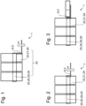
- Figures 1 to 3 each show schematic representations of an embodiment of a packaging device and a method for producing packaging units.
- Fig. 4 shows the arrangement according to Fig. 3 in a top view.
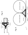
- Figures 5 and 6 each show different designs of an anvil tool.
- the Figures 1 to 3 each show a schematic representation of an embodiment of a packaging device 1 and a method for producing packaging units 20.
- the Fig. 4 shows the arrangement according to Fig. 3 in a top view.
- the Fig. 5 also shows the overlap area Ü from Fig. 4 in enlarged view.
- a packaging unit 20 comprises an article arrangement 21 of at least two articles 22 in an outer packaging 25.
- the outer packaging 25 is preferably made of an outer packaging material 26 which partially envelops the article arrangement 21 and in particular holds it together mechanically.
- the outer packaging material 26 is preferably an outer packaging material 26 consisting of paper or cardboard, in particular a pure paper material or cardboard material that does not contain any plastic components.
- the packaging device 1 can also be used to process an outer packaging material 26 with a plastic component, for example a plastic-coated paper material or cardboard material, a paper-plastic composite material or the like.
- a plastic component for example a plastic-coated paper material or cardboard material, a paper-plastic composite material or the like.
- the outer packaging 25 is a strapping band 28, in particular a paper banderol 29.
- a strapping band 28 in particular a paper banderol 29.
- cardboard material or a pulp material or even a paper or cardboard-containing composite material of sufficient strength and stability is also suitable as strapping band material, provided that it can meet the necessary strength requirements after the strapping band 28 has been produced.
- the articles 22 are preferably beverage containers, in particular bottles made of PET or another suitable plastic or cans 24 made of plastic and/or aluminium or similar.
- the packaging device 1 is also suitable for combining other suitable articles 22 in a corresponding outer packaging 25 as packaging units 20 or bundles.
- suitable articles 22 in a corresponding outer packaging 25 as packaging units 20 or bundles.
- at least two similar or at least two identically designed articles 22 can be provided as an article group 21.
- the packaging unit 20 comprises at least two beverage containers, in particular bottles or cans 24, which are preferably combined by at least one strapping or strapping band 28 made of pure paper material.
- the articles 22 are designed as cans 24 and in a packaging unit 20 six cans 24 are packed by means of a Paper banderole 29, with the cans 24 each arranged in two parallel rows of three (see in particular the top view in Fig. 4 ).
- the paper band 29 is stretched under tension around the outward-facing outer surfaces of the cans 24 and in this way holds the cans 24 together mechanically.
- free ends 30 of the paper band 29 are arranged to at least partially overlap.
- the free ends 30 are arranged in an overlapping area Ü, which is assigned to an area in which two adjacent articles 22 come into contact.
- the two articles 22 are arranged next to one another or adjacent to one another or bordering one another in the area.
- the overlapping area Ü the free ends 30 of the paper band 29 are joined together to form a joint connection 40, this being carried out in particular with a packaging device 1 according to the invention and/or according to the method according to the invention.
- An outer packaging material 26 is arranged on an article arrangement 21, for example, assembled in a single-part module (not shown), by an application device 8.
- the application device 8 according to the embodiment shown here is formed by a strapping module 9, which is designed to attach the outer packaging material 26 to the article arrangement 21, in particular to attach a paper band 29, which is stretched under tension around the outer surface of the cans 24.
- the strapping module 9 can comprise a corresponding tensioning device, as is known from the prior art.
- the packaging device 1 is equipped with an ultrasonic joining device 5 for forming a joint 40.
- the ultrasonic joining device 5 comprises at least one anvil tool 6 and at least one sonotrode 7.
- the anvil tool 6 is at least partially inserted and arranged between the cans 24 of the article arrangement 21, in particular the anvil tool 6 is at least partially inserted between the cans 24 in an area below the strapping area.
- the strapping area is the area in which the paper band 29 is arranged on the article arrangement 21.
- the Anvil tool 6 is laterally assigned to the overlap area Ü, in which overlap area Ü the two free ends 30, 30-1, 30-2 of the paper banderole 29 are arranged overlapping each other.
- the arrangement of the anvil tool 6 between the cans 24 takes place, for example, at a time when the outer packaging material 26 has not yet been applied to the article arrangement 21.
- the arrangement of the anvil tool 6 can, however, also take place at the same time as the article arrangement 21 is wrapped with the paper band 29.
- the paper band 29 can first be wrapped around the articles 22 and then the anvil tool 6 can be arranged below or above the strapping area between the cans 24.
- the anvil tool 6 is designed to be adjustable in height. By moving the anvil tool 6 upwards, it is arranged at the height of the paper band 29 and in particular adjacent to the overlapping free ends 30 of the paper band 29 stretched around the articles 22.
- the anvil tool 6 is arranged at a first height above the position of the paper band 29 and is assigned to the overlap region Ü by being moved downwards, wherein the anvil tool 6 is arranged in particular between the articles 22 and the free end regions 30 of the strapping band 28 which at least partially overlap one another.
- the sonotrode 7 of the ultrasonic joining device 5 is shown in schematic form. This is arranged to the side of the anvil tool 6 arranged at least partially between the cans 23 and to the side of the overlap area Ü of the two free ends 30, 30-1, 30-2, so that the two free ends 30, 30-1, 30-2 of the paper banderole 29 are preferably clamped between the anvil tool 6 and the sonotrode 7.
- the sonotrode 7 is designed to be laterally movable, so that the sonotrode 7 can be fed laterally to the anvil tool 6 and the overlapping region Ü with the overlapping free ends 30 of the paper banderol 29.
- the sonotrode 7 is adjustable in height in order to adapt to the height at which the Paper banderole 20 is arranged on the article arrangement 21, in a simple and quick manner so that the ultrasonic joining device 5 can be used for different products.
- the overlapping free ends 30 By subjecting the overlapping free ends 30 to ultrasonic vibration, they are joined and connected via a so-called ultrasonic welding process, in particular via a so-called ultrasonic friction welding process.
- anvil tool 6 and the sonotrode 7 can be pressed against each other to support the ultrasonic welding process.
- the ultrasonic joining device 5 is assigned a moistening device (not shown), with which the outer packaging material 26 is moistened, for example with water or steam, at least in the overlapping region of the two free ends 30-1, 30-2, in order to further promote the joining process.
- the anvil tool 6 is pulled out of the finished packaging unit 20 by moving it downwards and then moving it sideways.
- the packaging unit 20 can now be fed for further handling, for example to a palletizing device or similar.
- FIG. 5 and 6 each show different embodiments of an anvil tool 6. It is provided that at least one contour 10 of the anvil tool 6 is adapted to article 22 of the article arrangement 21.
- a first contour 10-1 of the anvil tool 6 is assigned to a first article 22-1 of the article arrangement 21 and a second contour 10-2 of the anvil tool 6 is assigned to a second article 22-2 of the article arrangement 21.
- the adapted contour 10 of the anvil tool 6 is thus formed by a region of the anvil tool 6 that is not involved in the production of the joint connection 40.
- the shape of the contour 10 is in particular designed such that the anvil tool 6 can be advantageously positioned at least partially between the articles 22. in order to be able to produce the joint 40 between the free ends 30 of the paper banderole 29 accordingly.
- the contour 10 has a correspondingly formed concave curvature.
- a first contour region 10-1 with a first concave curvature and a second contour region 10-2 with a second concave curvature are provided ( Fig. 6 ).
- the anvil tool 6 can, for example, have at least one triangular cross-sectional area 11, which can advantageously be at least partially introduced and arranged in the space Z between two adjacent articles 22 (see, for example, the Fig. 5 ).
- the anvil tool 6 has an at least partially structured surface at least in the area of the contour 10.
- the surface can have a rough structure, the surface can be corrugated or have elevations and/or depressions or the like.
- the structured surface can also contain a grid-like surface structure, have regular patterns of elevations and depressions or other surface designs.
Landscapes
- Engineering & Computer Science (AREA)
- Mechanical Engineering (AREA)
- Packages (AREA)
- Auxiliary Devices For And Details Of Packaging Control (AREA)
- Packaging Of Special Articles (AREA)
Applications Claiming Priority (2)
| Application Number | Priority Date | Filing Date | Title |
|---|---|---|---|
| DE102020131191.5A DE102020131191A1 (de) | 2020-11-25 | 2020-11-25 | Verpackungsvorrichtung und Verfahren zum Herstellen von Verpackungseinheiten |
| EP21205969.5A EP4005936B1 (fr) | 2020-11-25 | 2021-11-02 | Dispositif d'emballage et procédé de fabrication d'unités d'emballage |
Related Parent Applications (2)
| Application Number | Title | Priority Date | Filing Date |
|---|---|---|---|
| EP21205969.5A Division EP4005936B1 (fr) | 2020-11-25 | 2021-11-02 | Dispositif d'emballage et procédé de fabrication d'unités d'emballage |
| EP21205969.5A Division-Into EP4005936B1 (fr) | 2020-11-25 | 2021-11-02 | Dispositif d'emballage et procédé de fabrication d'unités d'emballage |
Publications (2)
| Publication Number | Publication Date |
|---|---|
| EP4438504A2 true EP4438504A2 (fr) | 2024-10-02 |
| EP4438504A3 EP4438504A3 (fr) | 2024-12-04 |
Family
ID=78500502
Family Applications (2)
| Application Number | Title | Priority Date | Filing Date |
|---|---|---|---|
| EP21205969.5A Active EP4005936B1 (fr) | 2020-11-25 | 2021-11-02 | Dispositif d'emballage et procédé de fabrication d'unités d'emballage |
| EP24193116.1A Withdrawn EP4438504A3 (fr) | 2020-11-25 | 2021-11-02 | Dispositif d'emballage et procédé de fabrication d'unités d'emballage |
Family Applications Before (1)
| Application Number | Title | Priority Date | Filing Date |
|---|---|---|---|
| EP21205969.5A Active EP4005936B1 (fr) | 2020-11-25 | 2021-11-02 | Dispositif d'emballage et procédé de fabrication d'unités d'emballage |
Country Status (4)
| Country | Link |
|---|---|
| EP (2) | EP4005936B1 (fr) |
| CN (1) | CN216684989U (fr) |
| DE (1) | DE102020131191A1 (fr) |
| ES (1) | ES2994447T3 (fr) |
Families Citing this family (3)
| Publication number | Priority date | Publication date | Assignee | Title |
|---|---|---|---|---|
| DE102023135419A1 (de) * | 2023-12-15 | 2025-06-18 | Mosca Gmbh | Umreifungsmaschine und -verfahren |
| DE202024101855U1 (de) | 2024-04-15 | 2024-05-08 | Project Service & Produktion GmbH | Verpackungseinrichtung |
| DE202024101856U1 (de) | 2024-04-15 | 2024-05-06 | Project Service & Produktion GmbH | Verpackungseinrichtung |
Family Cites Families (6)
| Publication number | Priority date | Publication date | Assignee | Title |
|---|---|---|---|---|
| CH685197A5 (de) | 1992-01-09 | 1995-04-28 | Automatic Taping Systems | Breitbandbinden von gestapeltem Packgut. |
| DE102009012388A1 (de) | 2008-09-03 | 2010-04-22 | Peter Suhling | Anlage zum Umreifen eines Bündels von Gegenständen |
| DE102009044271A1 (de) * | 2009-10-16 | 2011-04-28 | Krones Ag | Gebinde aus mehreren Behältern und Verfahren zur Herstellung eines solchen Gebindes |
| DE102013225743A1 (de) | 2013-12-12 | 2015-06-18 | Robert Bosch Gmbh | Utraschallfügeverfahren und Ultraschallfügevorrichtung |
| DE202014101317U1 (de) * | 2014-03-21 | 2014-03-31 | Project Automation & Engineering Gmbh | Umverpackung für ein Gebinde aus gruppierten Einzelwaren |
| DE102019113181A1 (de) | 2019-05-17 | 2020-11-19 | Krones Aktiengesellschaft | Umreifungsvorrichtung, Vorrichtung und Verfahren zur Herstellung eines wenigstens einen Artikel umfassenden Gebindes |
-
2020
- 2020-11-25 DE DE102020131191.5A patent/DE102020131191A1/de active Pending
-
2021
- 2021-10-14 CN CN202122481263.7U patent/CN216684989U/zh active Active
- 2021-11-02 ES ES21205969T patent/ES2994447T3/es active Active
- 2021-11-02 EP EP21205969.5A patent/EP4005936B1/fr active Active
- 2021-11-02 EP EP24193116.1A patent/EP4438504A3/fr not_active Withdrawn
Also Published As
| Publication number | Publication date |
|---|---|
| ES2994447T3 (en) | 2025-01-23 |
| CN216684989U (zh) | 2022-06-07 |
| DE102020131191A1 (de) | 2022-05-25 |
| EP4005936A1 (fr) | 2022-06-01 |
| EP4005936C0 (fr) | 2024-09-11 |
| EP4005936B1 (fr) | 2024-09-11 |
| EP4438504A3 (fr) | 2024-12-04 |
Similar Documents
| Publication | Publication Date | Title |
|---|---|---|
| EP2301852B1 (fr) | Gerbe constituée de plusieurs récipients et procédé de fabrication de la gerbe | |
| EP4005936B1 (fr) | Dispositif d'emballage et procédé de fabrication d'unités d'emballage | |
| EP4416064B1 (fr) | Procédé, dispositif d'application et dispositif d'emballage pour produire des unités d'emballage | |
| EP4416063B1 (fr) | Procédé, dispositif d'application et dispositif d'emballage pour la fabrication de paquets cerclés | |
| DE102020125405A1 (de) | Umreifungsgebinde, Umreifungsmaschine und Verfahren zur Herstellung von Umreifungsgebinden | |
| DE4338799A1 (de) | Verpackung für Bücher und/oder andere Produkte sowie Verfahren und Vorrichtung zu ihrer Herstellung | |
| EP4277850A1 (fr) | Dispositif de cerclage et procédé de fabrication d'emballages à cerclage | |
| EP4091965B1 (fr) | Emballage cerclé, procédé de fabrication d'emballages cerclés, ainsi qu'outil pour la fabrication d'emballages cerclés | |
| EP4274784A1 (fr) | Procédé et outil pour produire des emballages de cerclage | |
| WO2021043623A1 (fr) | Procédé et dispositif de conditionnement pour produire des unités d'emballage | |
| DE102020101934A1 (de) | Verpackungseinheit, Verfahren zur Herstellung von Verpackungseinheiten und Verpackungsvorrichtung | |
| DE102019113182A1 (de) | Gebinde, Verpackungsvorrichtung zur Herstellung eines Gebindes und Verfahren zur Herstellung eines Gebindes | |
| DE102022128394A1 (de) | Verpackungseinheit, Verfahren zur Herstellung von Verpackungseinheiten und Verpackungsvorrichtung | |
| DE102018201405A1 (de) | Verfahren und Vorrichtung zur Herstellung von Klebegebinden | |
| EP4370438A1 (fr) | Unité d'emballage, appareil de production d'une unité d'emballage, et procédé de production d'une unité d'emballage | |
| EP0621127A1 (fr) | Procédé et dispositif pour fabriquer des éléments de garnissage en carton ondulé | |
| DE102020131189A1 (de) | Verpackungsvorrichtung und Verfahren zum Herstellen von Verpackungseinheiten | |
| DE102023110390A1 (de) | Vorrichtung und Verfahren zum Applizieren mindestens einer Umreifung um eine Zusammenstellung umfassend mindestens zwei Artikel | |
| DE102017203660A1 (de) | Mit schrumpfbarer Folie umhülltes Verpackungsgut sowie Verfahren und Verpackungsmaschine zu dessen Herstellung | |
| EP4001132A1 (fr) | Unité d'emballage, procédé de fabrication d'unités d'emballage et dispositif d'emballage | |
| DE102020132464A1 (de) | Umreifungsgebinde, Verfahren zu deren Herstellung sowie Vorrichtung zur Herstellung von Umreifungsgebinden | |
| DE102020109631A1 (de) | Verfahren zur Herstellung eines Gebindes und Verpackungsvorrichtung zur Herstellung eines Gebindes | |
| DE102020124015A1 (de) | Verpackungsvorrichtung zur Herstellung von Verpackungseinheiten, Verpackungseinheit und ein Verfahren zur Herstellung von Verpackungseinheiten | |
| DE102020101932A1 (de) | Verpackungseinheit, Verpackungsvorrichtung und Verfahren zur Herstellung von Verpackungseinheiten | |
| EP4458720A2 (fr) | Unité d'emballage, bande de cerclage et procédé de fabrication d'une bande de cerclage ou de fabrication d'une unité d'emballage |
Legal Events
| Date | Code | Title | Description |
|---|---|---|---|
| PUAI | Public reference made under article 153(3) epc to a published international application that has entered the european phase |
Free format text: ORIGINAL CODE: 0009012 |
|
| STAA | Information on the status of an ep patent application or granted ep patent |
Free format text: STATUS: THE APPLICATION HAS BEEN PUBLISHED |
|
| AC | Divisional application: reference to earlier application |
Ref document number: 4005936 Country of ref document: EP Kind code of ref document: P |
|
| AK | Designated contracting states |
Kind code of ref document: A2 Designated state(s): AL AT BE BG CH CY CZ DE DK EE ES FI FR GB GR HR HU IE IS IT LI LT LU LV MC MK MT NL NO PL PT RO RS SE SI SK SM TR |
|
| REG | Reference to a national code |
Ref country code: DE Ref legal event code: R079 Free format text: PREVIOUS MAIN CLASS: B65B0027040000 Ipc: B65B0013320000 |
|
| PUAL | Search report despatched |
Free format text: ORIGINAL CODE: 0009013 |
|
| AK | Designated contracting states |
Kind code of ref document: A3 Designated state(s): AL AT BE BG CH CY CZ DE DK EE ES FI FR GB GR HR HU IE IS IT LI LT LU LV MC MK MT NL NO PL PT RO RS SE SI SK SM TR |
|
| RIC1 | Information provided on ipc code assigned before grant |
Ipc: B65B 27/04 20060101ALI20241030BHEP Ipc: B31F 5/00 20060101ALI20241030BHEP Ipc: B31B 50/66 20170101ALI20241030BHEP Ipc: B65B 13/32 20060101AFI20241030BHEP |
|
| STAA | Information on the status of an ep patent application or granted ep patent |
Free format text: STATUS: REQUEST FOR EXAMINATION WAS MADE |
|
| 17P | Request for examination filed |
Effective date: 20250602 |
|
| STAA | Information on the status of an ep patent application or granted ep patent |
Free format text: STATUS: THE APPLICATION HAS BEEN WITHDRAWN |
|
| 18W | Application withdrawn |
Effective date: 20250903 |