EP4438541A1 - Procédé de surveillance des freins d'ascenseur et agencement d'ascenseur - Google Patents
Procédé de surveillance des freins d'ascenseur et agencement d'ascenseur Download PDFInfo
- Publication number
- EP4438541A1 EP4438541A1 EP23165390.8A EP23165390A EP4438541A1 EP 4438541 A1 EP4438541 A1 EP 4438541A1 EP 23165390 A EP23165390 A EP 23165390A EP 4438541 A1 EP4438541 A1 EP 4438541A1
- Authority
- EP
- European Patent Office
- Prior art keywords
- test
- torque
- brake
- ramping
- motor
- Prior art date
- Legal status (The legal status is an assumption and is not a legal conclusion. Google has not performed a legal analysis and makes no representation as to the accuracy of the status listed.)
- Pending
Links
Images
Classifications
-
- B—PERFORMING OPERATIONS; TRANSPORTING
- B66—HOISTING; LIFTING; HAULING
- B66B—ELEVATORS; ESCALATORS OR MOVING WALKWAYS
- B66B5/00—Applications of checking, fault-correcting, or safety devices in elevators
- B66B5/0087—Devices facilitating maintenance, repair or inspection tasks
- B66B5/0093—Testing of safety devices
-
- B—PERFORMING OPERATIONS; TRANSPORTING
- B66—HOISTING; LIFTING; HAULING
- B66B—ELEVATORS; ESCALATORS OR MOVING WALKWAYS
- B66B5/00—Applications of checking, fault-correcting, or safety devices in elevators
- B66B5/0006—Monitoring devices or performance analysers
- B66B5/0037—Performance analysers
Definitions
- the invention relates to monitoring the condition of the brakes of an elevator arrangement.
- the elevator arrangement is in particular suitable for vertically transporting passengers and/or goods.
- Elevators typically have an elevator car and a counterweight, which are interconnected by a hoisting roping passing around a drive member, which drive member is rotatable by a motor.
- the drive member can be a traction sheave, for example.
- These movable units of the elevator are usually on opposite sides of the drive member such that when one is moved upwards by rotating the drive member, the other moves downwards. The balance situation depends on prevailing load of the car, position of the car as well as design choices made with regard to weight difference of an empty elevator car and the counterweight.
- the motor can be used for producing or resisting rotation of the drive member.
- the motor can produce torque on the drive member, which torque can urge the drive member to rotate or resist rotation of the drive member, depending on situation and prevailing deviation from balance.
- the direction of the motor torque may sometimes be opposite to the rotation direction and sometimes the rotation direction.
- Elevators typically also have electromechanical brakes (also referred to as brake units), which can apply braking force directly to the drive member or to some other rotatable component of the elevator hoisting machinery, which is connected to the drive member, such as to a motor shaft or a brake disc, for example.
- the braking force produces a torque on the component on which they act on, which torque resists rotation of the component.
- the object of the invention is to introduce an improved method and elevator arrangement whereby condition of an elevator hoisting machinery can be tested and/or predicted.
- An object is particularly to introduce a solution by which it can be determined what is the actual braking torque each individual brake unit of a multi-brake elevator hoisting machinery is capable of.
- An object is further to introduce a solution facilitating determining and/or forecasting sufficiency of the braking effect of the individual brake unit with an improved accuracy.
- hoisting machinery comprises a motor, a drive member rotatable by the motor, and three or more brake units for braking rotation of the drive member, each brake unit being shiftable between open (i.e. non-braking) position I and closed (i.e. braking) position II.
- the method comprises performing a test sequence, wherein the test sequence comprises:
- condition of the brake units of the multi-brake elevator hoisting machinery may be determined with an increased accuracy. It may also be possible to predict possible changes in said working condition, for example by analyzing a trend of the braking torques registered during consecutive test events. This prediction may also be carried out remotely, for example by means of a cloud computing system, and results may be utilized when scheduling maintenance visits to elevator sites.
- the test configuration in said changing the test configuration, is changed such that at least one brake unit that was held in closed position II during the previous test sequence is held in open position I in the repeated test sequence and/or such that at least one brake unit that was held in open position I during the previous test sequence is held in closed position II in the repeated test sequence.
- test sequence comprises:
- said determining condition of the brake units comprises comparing the individual braking torque of each individual brake unit with at least one limit.
- the method is performed automatically by a controlling and monitoring system, wherein the controlling and monitoring system preferably comprises one or more microprocessors and a memory storing a computer program for performing one or more steps of the method, preferably in particular the steps (100, 200, 300 and 400).
- the controlling and monitoring system preferably comprises one or more microprocessors and a memory storing a computer program for performing one or more steps of the method, preferably in particular the steps (100, 200, 300 and 400).
- a gradually increasing or reducing test torque is exerted by the motor on the drive member.
- test torque is increased gradually, in particular from zero torque or an initial non-zero torque (Tinitial1).
- torque is reduced gradually from an initial non-zero torque (Tinitial2).
- said gradually increasing or reducing torque is performed in stepwise manner. After each stepwise increase, a constant test torque is exerted for a period, the period preferably being 20-200 ms, more preferably 50-150 ms, most preferably about or exactly 100 ms.
- the method comprises, when starting the test sequence, exerting an initial torque (Tinitial) by the motor on the drive member against opposite direction torque exerted on the drive member by components external to hoisting machinery , in particular by a hoisting roping suspending movable elevator units, in particular a car and counterweight, in particular for counteracting at least partially said opposite direction torque and for preventing with the initial torque (Tinitial) rotation of the drive member already when starting the test sequence.
- the registering comprises storing the magnitude of the test torque (Ttest) into a memory of a controlling and monitoring system of the elevator arrangement.
- each brake unit is operable separately from each other. More specifically, each brake unit preferably comprises an actuator operable separately from actuators of other brake units.
- each said brake unit comprises a brake member movable in closed position where it is in contact with a part of the hoisting machinery which part is rotatable together with the drive member, and to an open position where it is out of contact with said part.
- the method comprises performing a reference test sequence where steps (101-105) similar to those of a test sequence, are performed such that in the holding (step 101) all the brake units are held in closed position.
- steps (101-105) similar to those of a test sequence are performed such that in the holding (step 101) all the brake units are held in closed position.
- elevator arrangement comprises a multi-brake elevator hoisting machinery comprising
- controlling and monitoring system is configured to perform a test sequence, and as part of the test sequence:
- controlling and monitoring system is configured as part of the test sequence:
- the elevator arrangement comprises:
- the controlling and monitoring system comprises one or more microprocessors and a memory storing a computer program for performing one or more steps of the method as described anywhere above or in any of the claims of the application, preferably in particular the steps 100, 200, 300 and 400.
- the elevator arrangement In a preferred embodiment of the method or the elevator arrangement, the whole time of the test sequences, the elevator arrangement is out of use for transporting passengers and/or goods.
- the motor is an electric motor.
- the elevator arrangement is for vertically transporting passengers and/or goods inside a car thereof.
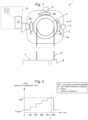
- FIGS 1 and 3 illustrate an elevator arrangement 1 according to an embodiment, which elevator arrangement comprises a multi-brake elevator hoisting machinery 2 comprising a motor 3; a drive member 4 rotatable by the motor 3.
- the motor 3 is an electric motor.
- the hoisting machinery 2 further comprises three or more brake units 5 for braking rotation of the drive member 4.
- Each brake unit 5 is shiftable between open (i.e. non-braking) position I and closed (i.e. braking) position II.
- the brake units 5 are illustrated schematically. The details of the actuating means of the brake units 5 are not illustrated.
- a brake member 5a of the brake unit 5 when a brake unit 5 is in the closed position II, a brake member 5a of the brake unit 5 is in contact with a part 4a of the hoisting machinery 2 which part 4a is rotatable together with the drive member 4, and when a brake unit 5 is in the open position I, a brake member 5a of the brake unit 5 is out of contact with the part 4a.
- the elevator arrangement 1 comprises a hoisting roping 6 passing around the drive member 4; and a first movable unit 7 and a second movable unit 8, one of them being an elevator car and the other preferably a counterweight, which movable units 7,8 are interconnected by the hoisting roping 6, and suspended by the hoisting roping 6 on opposite sides of the drive member 4, in particular such that when the drive member 4 rotates in its first direction the first movable unit 7 is moved upwards and the second movable unit 8 is moved downwards.
- the elevator arrangement 1 further comprises a controlling and monitoring system 12.
- the controlling and monitoring system 12 is connected to the hoisting machinery 2, in particular such that it can control the motor and the brake units 5 thereof.
- the controlling and monitoring system 12 comprises an elevator control 10 for controlling the brake units 5 and the motor 3.
- the controlling and monitoring system 12 comprises a remote monitoring unit or system 11 for monitoring the hoisting machinery 2 over a data bus, but this is not necessary since this function could be alternatively performed by the elevator control 11, and thereby locally.
- the controlling and monitoring system 12 is configured to execute a method for monitoring brakes of a multi-brake hoisting machinery 2 of an elevator arrangement 1 as will be described hereinafter.
- Figure 1 illustrates the elevator arrangement 1 executing the method according to a first embodiment
- Figure 2 illustrates an exemplary torque curve realized in the method according to the first embodiment
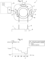
- Figure 3 illustrates the elevator arrangement 1 executing the method according to a second embodiment
- Figure 4 illustrates an exemplary torque curve realized in the method according to the first embodiment
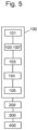
- Figure 5 illustrates steps of the method.
- the method for monitoring brakes of a multi-brake hoisting machinery 2 of an elevator arrangement 1 comprises performing a test sequence 100 where the test sequence comprises holding 101 at least one brake unit 5, which is in the preferred embodiment only one brake unit 5, in the open position while holding the rest of the brake units 5 in the closed position.
- the test sequence further comprises ramping 102 up a test torque with the motor 3, in particular during said holding 101.
- the ramping is illustrated in Figure 2 .
- a gradually increasing test torque is exerted by the motor 3 on the drive member 4.
- the test torque is increased gradually, in particular from zero torque or an initial non-zero torque Tinitial1. This is preferably implemented such that the torque reference of the motor 3 is increased gradually, preferably stepwise.
- the test torque is increased gradually in stepwise manner as visible in Figure 2 .
- a constant test torque is exerted for a period by the motor 3 on the drive member 4, the period preferably being 20-200 ms, more preferably 50-150 ms, most preferably about or exactly 100 ms.
- movement is likely to occur if the prevailing test torque exceeds the holding ability of the closed brake units 5, and this kind of period is long enough to enable detection of the movement reliably yet the rotation is unlikely to reach a harmfully high speed.
- the test sequence further comprises monitoring 103 movement of a component, which is preferably a component of the hoisting machine 2, during the ramping 102.
- Said component is preferably the rotor of the motor 3 or the drive member 4.
- the test sequence further comprises detecting 104 starting of movement of said component or that amount of movement exceeds a limit amount during the ramping 102 and registering 105 the magnitude of the test torque Ttest at the moment when the movement started or exceeded a limit amount, respectively.
- the method further comprises repeating 200 the performing 100 a test sequence one or more times with a new test configuration, the combinations of brake units 5 held in open position and in closed position being different in the test sequences.
- repeating 200 data is collected of different test configurations.
- the method comprises determining 300 an individual braking torque Ti of each individual brake unit 5 based on the registered magnitudes of test torques Ttest.
- the method further comprises determining 400 condition of the brake units 5 and/or predicting condition of the brake units 5 based on said individual braking torques Ti.
- test sequences 100 are repeated [in said repeating 200] until every individual brake unit 5 has been held alone in the open position during a ramping 102.
- each repeated test sequence can look otherwise similar to what is disclosed in Figure 2 , but the magnitude of the Ttest can be different depending on the condition of the individual brake units 5 being held in closed position.
- each said repeating 200 comprises changing the test configuration.
- said changing the test configuration comprises opening at least one brake unit 5 that was held in closed position II during the previous test sequence 100 and closing at least one brake unit 5 that was held in open position I during the previous test sequence 100.
- Said determining 300 braking torque of each individual brake unit 5 based on the registered magnitudes of test torques comprises calculating the braking torque of each individual brake unit 5.
- the magnitude of the test torque Ttest indicates a total braking torque without any braking effect contributed by the single brake unit 5 that is held open.
- Repeated test sequences in different test configurations provide enough information to calculate the braking torque Ti of each individual brake unit 5.
- enough data can be collected so that by relatively simple mathematics braking torques of individual brake units 5 can be calculated.
- test sequences are performed in the method in an unbalanced test situation, i.e. in a situation where torque is exerted on the drive member 4 by components 6,7,8 external to hoisting machinery 2, such as in particular by a hoisting roping 6 suspending movable elevator units 7,8, e.g. a car 7 and counterweight 8, this torque can be taken into account in the calculation.
- the method for monitoring brakes of a multi-brake hoisting machinery 2 of an elevator arrangement 1 comprises performing 100 a test sequence where the test sequence comprises holding 101 at least one brake unit 5, which is in the preferred embodiment all but one brake units 5, in the open position while holding the rest of the brake units 5, which is in the preferred embodiment only one brake unit 5, in the closed position.
- the test sequence further comprises ramping 102' down a test torque with the motor 3, in particular during said holding 101.
- the ramping 102' down is illustrated in Figure 4 .
- a gradually reducing test torque is exerted by the motor 3 on the drive member 4.
- the test torque is reduced gradually, in particular from an initial non-zero torque Tinitial2. This is preferably implemented such that the torque reference of the motor 3 is reduced gradually, preferably stepwise.
- the test torque is reduced gradually in stepwise manner as visible in Figure 4 .
- a constant test torque is exerted for a period by the motor 3 on the drive member 4, the period preferably being 20-200 ms, more preferably 50-150 ms, most preferably about or exactly 100 ms.
- movement is likely to occur if the prevailing test torque exceeds the holding ability of the closed brake units 5, and this kind of period is long enough to enable detection of the movement reliably yet the rotation is unlikely to reach a harmfully high speed.
- An initial non-zero initial torque Tinitial2 is needed in most cases for holding the car and hoisting roping still, because in most elevators there is a weight difference between an empty elevator car and the counterweight, which together with possible additional unbalance of a hoisting roping (e.g. caused by car position-based unbalance of roping) might exceed the ability of the small number of brake units 5 (here only one) in closed position. Thereby, a substantial initial torque at the start of the test sequence may be needed for preventing movement due to said weight difference immediately after opening of the brake units 5 which are to be held during the test sequence.
- the method comprises, when starting each test sequence 100, exerting an initial [non-zero] torque Tinitial by the motor 3 on the drive member 4 against opposite direction torque (also referred to as the external torque) exerted on the drive member 4 by components 6,7,8 external to hoisting machinery 2, in particular by a hoisting roping 6 suspending movable elevator units 7,8, in particular a car 7 and counterweight 8, in particular for counteracting at least partially said opposite direction torque and for preventing with the initial torque Tinitial rotation of the drive member 4 already when starting the test sequence 100.
- opposite direction torque also referred to as the external torque
- the test sequence further comprises detecting 104 starting of movement of said component or that amount of movement of said component exceeds a limit amount during the ramping 102' and registering 105 the magnitude of the test torque Ttest at the moment when the movement started or exceeded a limit amount, respectively.
- the magnitude of the test torque is illustrated by Ttest.
- this Ttest is registered, e.g. by storing it into a memory of the controlling and monitoring system 12.
- the method further comprises repeating 200 the performing 100 a test sequence one or more times with a new test configuration, the combinations of brake units 5 held in open position and in closed position being different in the test sequences.
- repeating 200 data is collected of different test configurations.
- the method comprises determining 300 an individual braking torque Ti of each individual brake unit 5 based on the registered magnitudes of test torques Ttest.
- the method further comprises determining 400 condition of the brake units 5 and/or predicting condition of the brake units 5 based on said individual braking torques Ti.
- test sequences 100 are repeated [in said repeating 200] until every individual brake unit 5 has been held alone in the closed position during a ramping 102' down of a test sequence.
- each repeated test sequence can look otherwise similar to what is disclosed in Figure 2 , but the magnitude of the Ttest can be different depending on the condition of the individual brake unit 5 being held in closed position.
- each said repeating 200 comprises changing the test configuration.
- said changing the test configuration comprises opening a brake unit 5 that was held closed during previous test sequence 100 and closing a brake unit 5 that was held open during previous test sequence 100.
- Said determining 300 braking torque of each individual brake unit 5 based on the registered magnitudes of test torques Ttest may comprise calculating the braking torque of each individual brake unit 5.
- the magnitude of the test torque Ttest gives a torque value for an individual brake unit 5 which value can, in principle, directly be considered as the braking torque of each individual brake unit 5.
- the calculating could involve calculating the difference of each magnitude of test torque Ttest and the external torque prevailing during the test sequence. This is preferable in the case of the second embodiment for instance where the external torque is directed oppositely relative to the test torque.
- said determining condition of the brake units 5 can comprise comparing the individual braking torque Ti of each individual brake unit 5 with at least one limit.
- the method is preferably performed automatically by a controlling and monitoring system 12.
- the controlling and monitoring system 12 preferably comprises one or more microprocessors and a memory storing a computer program for performing steps of the method.
- the controlling and monitoring system 12 may comprise an elevator control unit 10 and a remote monitoring unit 11, for example, in which case part of the steps of the method can be performed by the elevator control unit 10 and part of the steps of the method can be performed by the remote monitoring unit 11.
- the limit amount of movement of a component is preferably an amount of movement corresponding to displacement distance, which is within range 1-10 mm, preferably less than 5 mm, most preferably 1-3 mm.
- the limit amount of movement corresponds to a relatively small amount of movement, which is enough to reliably indicate that the test torque has exceeded the braking torque of the closed brake units 5.
- the elevator arrangement 1 comprises a controlling and monitoring system 12 configured to execute the method as described anywhere above referring to Figures 1-4 .
- the controlling and monitoring system 12 is configured to perform a test sequence 100, and as part of the test sequence 100:
- the controlling and monitoring system 12 is further configured to
- controlling and monitoring system 12 is more specifically preferably configured, as part of the test sequence:
- the controlling and monitoring system 12 is configured to perform automatically the steps of the method, preferably in particular the steps 100, 200, 300 and 400 as described earlier above.
- the controlling and monitoring system 12 preferably comprises one or more microprocessors and a memory storing a computer program for performing steps of the method, preferably in particular the steps 100, 200, 300 and 400 as described earlier above.
- the part 4a of the hoisting machinery 2 rotating together with the drive member 4 is preferably an integral part of the drive member 4 or a part rigidly connected to it.
- multi-brake elevator hoisting machinery refers to a hoisting machinery having more than two, such as three or four or even more individual brake units.
- Each said brake unit 5 preferably comprises an actuator (not shown) for moving the brake member 5a, such as a brake pad, of the brake unit 5.
- the actuator is preferably an electromechanics device, such as a solenoid or electromagnet.
- the actuator is preferably able to move, when actuated, the brake member 5a of the brake unit 5 against a spring force towards open position I.
- the brake member 5a is preferably held by aid of the force of the actuator against the spring force in open position I and in the step of holding the brake unit 5 in closed position II, the brake member 5a is preferably held by aid of the spring force in the closed position II.
- Each said holding can be realized by the controlling and monitoring system 12 by controlling of the actuator.
- the method comprises initiating the testing if at least one preset criteria is fulfilled.
- criteria may be, for example, an empty elevator car being located at a test location.
- Another criteria may be e.g. time of the day - test may be scheduled at the time of low traffic, such as during night time for example.
- test configurations In general, in the embodiments, examples of different test configurations have been presented. However it is to be understood, that number of individual brakes open/closed during the test may also vary from what is disclosed by examples. Repeated test sequences in different test configurations provide enough information to calculate the braking torque Ti of each individual brake unit 5. By repeating, enough data can be collected so that by relatively simple mathematics braking torques of individual brake units can be calculated also with different combinations than what are shown by way of illustrated examples in the application. For example, it is possible to determine individual braking torques with repeated test sequences where in the test configurations there are 2 brake units held in open position and 2 in closed position.
- the method can comprise performing a reference test sequence where the steps 101-105 are performed such that in the step 101 all the brake units are held in closed position.
- the magnitude of a maximum torque can be registered for being used as reference in a following determination step.
- step 300 in particular a calculation process thereof, can be further simplified since the difference between said magnitude of a maximum torque and the magnitude of each test torque caused by the open brake unit(s) reveals the effect of the brake units held open.
- the component movement of which is monitored in said monitoring 103 during the ramping 102; 102' is preferably a component of the hoisting machine 2.
- the component could also be some other movable component of the elevator arrangement 1, such as a rope, the movable unit 7 or 8 or a component of any one of these.
Landscapes
- Elevator Control (AREA)
- Maintenance And Inspection Apparatuses For Elevators (AREA)
Priority Applications (2)
| Application Number | Priority Date | Filing Date | Title |
|---|---|---|---|
| EP23165390.8A EP4438541A1 (fr) | 2023-03-30 | 2023-03-30 | Procédé de surveillance des freins d'ascenseur et agencement d'ascenseur |
| CN202410297664.2A CN118723738A (zh) | 2023-03-30 | 2024-03-15 | 方法和电梯装置 |
Applications Claiming Priority (1)
| Application Number | Priority Date | Filing Date | Title |
|---|---|---|---|
| EP23165390.8A EP4438541A1 (fr) | 2023-03-30 | 2023-03-30 | Procédé de surveillance des freins d'ascenseur et agencement d'ascenseur |
Publications (1)
| Publication Number | Publication Date |
|---|---|
| EP4438541A1 true EP4438541A1 (fr) | 2024-10-02 |
Family
ID=85792583
Family Applications (1)
| Application Number | Title | Priority Date | Filing Date |
|---|---|---|---|
| EP23165390.8A Pending EP4438541A1 (fr) | 2023-03-30 | 2023-03-30 | Procédé de surveillance des freins d'ascenseur et agencement d'ascenseur |
Country Status (2)
| Country | Link |
|---|---|
| EP (1) | EP4438541A1 (fr) |
| CN (1) | CN118723738A (fr) |
Cited By (1)
| Publication number | Priority date | Publication date | Assignee | Title |
|---|---|---|---|---|
| JP7828567B1 (ja) * | 2024-12-26 | 2026-03-12 | フジテック株式会社 | エレベータの制動トルク測定方法 |
Citations (4)
| Publication number | Priority date | Publication date | Assignee | Title |
|---|---|---|---|---|
| EP1701904B1 (fr) * | 2004-01-09 | 2011-11-30 | Kone Corporation | Methode pour tester l'etat des freins d'un ascenseur |
| TWI607949B (zh) * | 2014-10-01 | 2017-12-11 | 利愛電氣股份有限公司 | 電梯主機制動系統的測試方法 |
| EP3280666B1 (fr) * | 2015-04-07 | 2019-07-10 | Inventio AG | Vérification de la force de freinage d'un frein d'ascenseur |
| WO2023280400A1 (fr) | 2021-07-07 | 2023-01-12 | Kone Corporation | Procédé de test d'un frein d'une machine et d'un système de levage d'ascenseur |
-
2023
- 2023-03-30 EP EP23165390.8A patent/EP4438541A1/fr active Pending
-
2024
- 2024-03-15 CN CN202410297664.2A patent/CN118723738A/zh active Pending
Patent Citations (4)
| Publication number | Priority date | Publication date | Assignee | Title |
|---|---|---|---|---|
| EP1701904B1 (fr) * | 2004-01-09 | 2011-11-30 | Kone Corporation | Methode pour tester l'etat des freins d'un ascenseur |
| TWI607949B (zh) * | 2014-10-01 | 2017-12-11 | 利愛電氣股份有限公司 | 電梯主機制動系統的測試方法 |
| EP3280666B1 (fr) * | 2015-04-07 | 2019-07-10 | Inventio AG | Vérification de la force de freinage d'un frein d'ascenseur |
| WO2023280400A1 (fr) | 2021-07-07 | 2023-01-12 | Kone Corporation | Procédé de test d'un frein d'une machine et d'un système de levage d'ascenseur |
Cited By (1)
| Publication number | Priority date | Publication date | Assignee | Title |
|---|---|---|---|---|
| JP7828567B1 (ja) * | 2024-12-26 | 2026-03-12 | フジテック株式会社 | エレベータの制動トルク測定方法 |
Also Published As
| Publication number | Publication date |
|---|---|
| CN118723738A (zh) | 2024-10-01 |
Similar Documents
| Publication | Publication Date | Title |
|---|---|---|
| CN101243000B (zh) | 电梯系统 | |
| US20100154527A1 (en) | Elevator Brake Condition Testing | |
| EP2537790B1 (fr) | Dispositif ascenseur | |
| JP5214239B2 (ja) | エレベータ装置 | |
| EP2221267B1 (fr) | Dispositif élévateur | |
| US10399818B2 (en) | Arrangement and a method for testing elevator safety gear | |
| EP3750837B1 (fr) | Ascenseur surveillant la traction de l'appareil de levage et sur la base de ces informations, ajuster la vitesse limite d'arrêt d'urgence. | |
| EP1792865A1 (fr) | Ascenseur | |
| US20170355560A1 (en) | System and method for monitoring elevator brake capability | |
| EP2743225B1 (fr) | Système d'ascenseur | |
| KR20180042314A (ko) | 엘리베이터 조절 시스템 및 엘리베이터 시스템 작동 방법 | |
| EP4438541A1 (fr) | Procédé de surveillance des freins d'ascenseur et agencement d'ascenseur | |
| US20260116703A1 (en) | Method for testing safety characteristics of an elevator | |
| CN107697752B (zh) | 电梯系统 | |
| JP5079288B2 (ja) | エレベータ装置 | |
| US12545553B2 (en) | Method for testing a brake of a hoisting machine and system | |
| JPH0840658A (ja) | エレベータの非常制動制御方法及び装置 | |
| JP2003182945A (ja) | エレベータの制動力測定装置および測定方法 | |
| HK40116393A (zh) | 方法和电梯装置 | |
| CN113387247A (zh) | 监测、处理和调整电梯紧急停止事件的设备、方法和程序 | |
| JPH0930750A (ja) | エレベーターのブレーキ特性評価装置 | |
| JP7655652B2 (ja) | 巻上機ブレーキの動トルク診断装置および動トルク診断方法 | |
| EP4332042B1 (fr) | Réglage d'une période de secours | |
| EP3945054B1 (fr) | Système de surveillance de l'état de frein actif de plate-forme à poutre | |
| HK40056726A (en) | Devices, methods and computer programs for monitoring, processing and adjusting an elevator emergency stopping event |
Legal Events
| Date | Code | Title | Description |
|---|---|---|---|
| PUAI | Public reference made under article 153(3) epc to a published international application that has entered the european phase |
Free format text: ORIGINAL CODE: 0009012 |
|
| STAA | Information on the status of an ep patent application or granted ep patent |
Free format text: STATUS: THE APPLICATION HAS BEEN PUBLISHED |
|
| AK | Designated contracting states |
Kind code of ref document: A1 Designated state(s): AL AT BE BG CH CY CZ DE DK EE ES FI FR GB GR HR HU IE IS IT LI LT LU LV MC ME MK MT NL NO PL PT RO RS SE SI SK SM TR |
|
| P01 | Opt-out of the competence of the unified patent court (upc) registered |
Free format text: CASE NUMBER: APP_858/2025 Effective date: 20250108 |
|
| STAA | Information on the status of an ep patent application or granted ep patent |
Free format text: STATUS: REQUEST FOR EXAMINATION WAS MADE |
|
| 17P | Request for examination filed |
Effective date: 20250331 |
|
| GRAP | Despatch of communication of intention to grant a patent |
Free format text: ORIGINAL CODE: EPIDOSNIGR1 |
|
| STAA | Information on the status of an ep patent application or granted ep patent |
Free format text: STATUS: GRANT OF PATENT IS INTENDED |
|
| INTG | Intention to grant announced |
Effective date: 20260127 |
|
| GRAS | Grant fee paid |
Free format text: ORIGINAL CODE: EPIDOSNIGR3 |
|
| GRAA | (expected) grant |
Free format text: ORIGINAL CODE: 0009210 |
|
| STAA | Information on the status of an ep patent application or granted ep patent |
Free format text: STATUS: THE PATENT HAS BEEN GRANTED |