EP4438858A2 - Procédé pour effectuer des mesures de service sur une installation de conversion d'énergie et installation de conversion d'énergie - Google Patents
Procédé pour effectuer des mesures de service sur une installation de conversion d'énergie et installation de conversion d'énergie Download PDFInfo
- Publication number
- EP4438858A2 EP4438858A2 EP24194316.6A EP24194316A EP4438858A2 EP 4438858 A2 EP4438858 A2 EP 4438858A2 EP 24194316 A EP24194316 A EP 24194316A EP 4438858 A2 EP4438858 A2 EP 4438858A2
- Authority
- EP
- European Patent Office
- Prior art keywords
- combustion chamber
- rotor
- compressor
- blades
- hot gas
- Prior art date
- Legal status (The legal status is an assumption and is not a legal conclusion. Google has not performed a legal analysis and makes no representation as to the accuracy of the status listed.)
- Pending
Links
Images






Classifications
-
- F—MECHANICAL ENGINEERING; LIGHTING; HEATING; WEAPONS; BLASTING
- F01—MACHINES OR ENGINES IN GENERAL; ENGINE PLANTS IN GENERAL; STEAM ENGINES
- F01D—NON-POSITIVE DISPLACEMENT MACHINES OR ENGINES, e.g. STEAM TURBINES
- F01D5/00—Blades; Blade-carrying members; Heating, heat-insulating, cooling or antivibration means on the blades or the members
- F01D5/005—Repairing methods or devices
-
- F—MECHANICAL ENGINEERING; LIGHTING; HEATING; WEAPONS; BLASTING
- F01—MACHINES OR ENGINES IN GENERAL; ENGINE PLANTS IN GENERAL; STEAM ENGINES
- F01D—NON-POSITIVE DISPLACEMENT MACHINES OR ENGINES, e.g. STEAM TURBINES
- F01D5/00—Blades; Blade-carrying members; Heating, heat-insulating, cooling or antivibration means on the blades or the members
- F01D5/12—Blades
- F01D5/14—Form or construction
- F01D5/18—Hollow blades, i.e. blades with cooling or heating channels or cavities; Heating, heat-insulating or cooling means on blades
-
- F—MECHANICAL ENGINEERING; LIGHTING; HEATING; WEAPONS; BLASTING
- F01—MACHINES OR ENGINES IN GENERAL; ENGINE PLANTS IN GENERAL; STEAM ENGINES
- F01D—NON-POSITIVE DISPLACEMENT MACHINES OR ENGINES, e.g. STEAM TURBINES
- F01D5/00—Blades; Blade-carrying members; Heating, heat-insulating, cooling or antivibration means on the blades or the members
- F01D5/12—Blades
- F01D5/28—Selecting particular materials; Particular measures relating thereto; Measures against erosion or corrosion
- F01D5/284—Selection of ceramic materials
-
- F—MECHANICAL ENGINEERING; LIGHTING; HEATING; WEAPONS; BLASTING
- F01—MACHINES OR ENGINES IN GENERAL; ENGINE PLANTS IN GENERAL; STEAM ENGINES
- F01D—NON-POSITIVE DISPLACEMENT MACHINES OR ENGINES, e.g. STEAM TURBINES
- F01D5/00—Blades; Blade-carrying members; Heating, heat-insulating, cooling or antivibration means on the blades or the members
- F01D5/12—Blades
- F01D5/28—Selecting particular materials; Particular measures relating thereto; Measures against erosion or corrosion
- F01D5/286—Particular treatment of blades, e.g. to increase durability or resistance against corrosion or erosion
-
- F—MECHANICAL ENGINEERING; LIGHTING; HEATING; WEAPONS; BLASTING
- F01—MACHINES OR ENGINES IN GENERAL; ENGINE PLANTS IN GENERAL; STEAM ENGINES
- F01D—NON-POSITIVE DISPLACEMENT MACHINES OR ENGINES, e.g. STEAM TURBINES
- F01D5/00—Blades; Blade-carrying members; Heating, heat-insulating, cooling or antivibration means on the blades or the members
- F01D5/12—Blades
- F01D5/28—Selecting particular materials; Particular measures relating thereto; Measures against erosion or corrosion
- F01D5/288—Protective coatings for blades
-
- F—MECHANICAL ENGINEERING; LIGHTING; HEATING; WEAPONS; BLASTING
- F05—INDEXING SCHEMES RELATING TO ENGINES OR PUMPS IN VARIOUS SUBCLASSES OF CLASSES F01-F04
- F05D—INDEXING SCHEME FOR ASPECTS RELATING TO NON-POSITIVE-DISPLACEMENT MACHINES OR ENGINES, GAS-TURBINES OR JET-PROPULSION PLANTS
- F05D2220/00—Application
- F05D2220/70—Application in combination with
- F05D2220/72—Application in combination with a steam turbine
-
- F—MECHANICAL ENGINEERING; LIGHTING; HEATING; WEAPONS; BLASTING
- F05—INDEXING SCHEMES RELATING TO ENGINES OR PUMPS IN VARIOUS SUBCLASSES OF CLASSES F01-F04
- F05D—INDEXING SCHEME FOR ASPECTS RELATING TO NON-POSITIVE-DISPLACEMENT MACHINES OR ENGINES, GAS-TURBINES OR JET-PROPULSION PLANTS
- F05D2230/00—Manufacture
- F05D2230/80—Repairing, retrofitting or upgrading methods
-
- F—MECHANICAL ENGINEERING; LIGHTING; HEATING; WEAPONS; BLASTING
- F05—INDEXING SCHEMES RELATING TO ENGINES OR PUMPS IN VARIOUS SUBCLASSES OF CLASSES F01-F04
- F05D—INDEXING SCHEME FOR ASPECTS RELATING TO NON-POSITIVE-DISPLACEMENT MACHINES OR ENGINES, GAS-TURBINES OR JET-PROPULSION PLANTS
- F05D2230/00—Manufacture
- F05D2230/90—Coating; Surface treatment
Definitions
- the invention relates to a method for carrying out service measures on an energy conversion plant and to an energy conversion plant.
- the object is achieved by a method according to claim 1 and an energy conversion plant according to claim 10, in which a corresponding existing gas turbine is provided or modified accordingly or is newly manufactured.
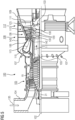
- the Figure 1 shows an example of a gas turbine machine 100 in a longitudinal section.
- the gas turbine machine 100 has inside a rotor 103 with turbine blade 120, which is rotatably mounted about a rotation axis 102 and is also referred to as turbine runner.
- the annular combustion chamber 110 communicates with a preferably annular hot gas channel 111.
- a preferably annular hot gas channel 111 There, for example, four turbine stages 112 connected in series form the turbine 108.
- Each turbine stage 112: I, II, III, IV is preferably formed from two blade rings.
- a row of guide vanes 115 in the hot gas channel 111 is followed by a row of rotor blades 125 formed from rotor blades 120.
- the guide vanes 130 are attached to a gas turbine housing 138 of a stator 143, whereas the rotor blades 120 of a rotor blade row 125 are attached to the rotor 103, for example by means of a turbine disk 133.
- a generator 5 ( Fig. 24 ) or a work machine (not shown).
- air 135 is sucked in by the compressor 105 through the intake housing 104 and compressed.
- the compressed air provided at the turbine end of the compressor 105 is fed to the burners 107 in a combustion chamber 110 and mixed there with a fuel.
- the mixture is then burned in the combustion chamber 110 to form the working medium 113.
- the working medium 113 flows along the hot gas channel 111 past the guide vanes 130 and the rotor blades 120.
- the working medium 113 expands at the rotor blades 120, transmitting momentum, so that the rotor blades 120 drive the rotor 103 and the rotor drives the work machine coupled to it.
- the components exposed to the hot working medium 113 are subject to thermal loads during operation of the gas turbine 100.
- the guide vanes 130 and rotor blades 120 of the first turbine stage 112, as seen in the flow direction of the working medium 113, are subjected to the greatest thermal load alongside the heat shield elements lining the combustion chamber 110.
- substrates of the components can have a directed structure, i.e. they are single-crystalline (SX structure) or have only longitudinally directed grains (DS structure).
- SX structure single-crystalline
- DS structure longitudinally directed grains
- iron-, nickel- or cobalt-based superalloys are used as materials for the components, in particular for the turbine blades 120, 130 and components of the combustion chamber 110.
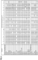
- Such superalloys are preferably made from EP 1 204 776 B1 , EP 1 306 454 , EP 1 319 729 A1 , WO 99/67435 or WO 00/44949 known or in Figure 4 listed.
- the blades 120, 130 can have coatings against corrosion: MCrAlX; M is at least one element from the group cobalt (Co), nickel (Ni), X is an active element and stands for yttrium (Y) and/or tantalum (Ta) and/or at least one element of the rare earths or hafnium (Hf) or iron (Fe).
- MCrAlX is at least one element from the group cobalt (Co), nickel (Ni)
- X is an active element and stands for yttrium (Y) and/or tantalum (Ta) and/or at least one element of the rare earths or hafnium (Hf) or iron (Fe).
- Such alloys are known from EP 0 486 489 B1 , EP 0 786 017 B1 , EP 0 412 397 B1 or EP 1 306 454 A1 .
- a thermal insulation layer may also be present on the MCrAlX, and may consist, for example, of ZrO 2 , Y 2 O 3 -ZrO 2 , ie it is not, partially or completely stabilized by yttrium oxide and/or calcium oxide and/or magnesium oxide and/or erbium oxide and/or ytterbium oxide.
- the guide vane 130 has a guide vane root (not shown here) facing the gas turbine casing 138 of the turbine 108 and a guide vane head opposite the guide vane root.
- the guide vane head faces the rotor 103 and is fixed to a fastening ring 140 of the stator 143.
- Figure 2 shows a combustion chamber 110 of a gas turbine.
- the combustion chamber 110 is designed, for example, as a so-called annular combustion chamber in which a plurality of Burners 107 open into a common combustion chamber 110, which generate flames 156.
- the combustion chamber 110 in its entirety is designed as an annular structure that is positioned around the axis of rotation 102.
- the combustion chamber 110 is designed for a comparatively high temperature of a working medium of approximately 1273K to 1873K.
- the combustion chamber wall 153 of the combustion chamber 110 is provided with an inner lining made of heat shield elements 155 on its side facing the working medium.
- Each heat shield element 155 made of an alloy is equipped with a particularly heat-resistant protective layer (MCrAlX layer and/or ceramic coating) on the working medium side or is made of high-temperature-resistant material (solid ceramic stones).
- M is at least one element from the group iron (Fe), cobalt (Co), nickel (Ni), X is an active element and stands for yttrium (Y) and/or silicon (Si) and/or tantalum (Ta) and/or at least one element from the rare earths or hafnium (Hf) and/or iron (Fe).
- Such alloys are known from the EP 0 486 489 B1 , EP 0 786 017 B1 , EP 0 412 397 B1 or EP 1 306 454 A1 .
- a ceramic thermal insulation layer may also be present on the MCrAlX and may consist of, for example, ZrO 2 , Y 2 O 3 -ZrO 2 , ie it is not, partially or completely stabilized by yttrium oxide and/or erbium oxide, ytterbium oxide and/or hafnium oxide.
- thermal barrier coating can have porous grains with micro- or macro-cracked surfaces for better thermal shock resistance.
- Heat shield elements 155 may need to have protective layers removed after use (e.g. by sandblasting). The corrosion and/or oxidation layers or products are then removed. If necessary, cracks in the heat shield element 155 are also repaired. The heat shield elements 155 are then recoated and used again.
- a cooling system can also be provided for the heat shield elements 155 or for their holding elements.
- the heat shield elements 155 are then hollow, for example, and may also have cooling holes (not shown) that open into the combustion chamber space 154.
- the Figure 3 shows in perspective view a rotor blade 120 or guide vane 130 of a turbomachine which extends along a longitudinal axis 121.
- the turbomachine can be a gas turbine of an aircraft or a power plant for generating electricity, a steam turbine or a compressor.
- the blade 120, 130 has, along its longitudinal axis, a fastening region 400, an adjacent blade platform 403, a blade 406 and a blade tip 415.
- a guide vane 130 As a guide vane 130, it may have a further platform at its blade tip 415 (not shown).
- a blade root 183 is formed, which is used to fasten the rotor blades 120, 130 to a shaft or a turbine disk 133 ( Fig. 1 ) serves.
- the blade base 183 is designed as a hammer head, for example. Other designs such as a Christmas tree or dovetail base are possible.
- the blade 120, 130 has a leading edge 409 and a trailing edge 412 for a medium flowing past the blade 406.
- Such superalloys are preferably made from EP 1 204 776 B1 , EP 1 306 454 , EP 1 319 729 A1 , WO 99/67435 or WO 00/44949 or from Figure 4 known.
- the blade 120, 130 can be manufactured by a casting process, also by means of directional solidification, by a forging process, by a milling process or combinations thereof.
- Workpieces with a single-crystal structure or structures are used as components for machines that are exposed to high mechanical, thermal and/or chemical stresses during operation.
- Such monocrystalline workpieces is carried out, for example, by directional solidification from the melt. This involves casting processes in which the liquid metallic alloy solidifies into a monocrystalline structure, i.e. into a monocrystalline workpiece, or solidifies in a directionally.
- dendritic crystals are aligned along the heat flow and form either a columnar grain structure, i.e. grains that run the entire length of the workpiece and are referred to here, in common parlance, as directionally solidified, or a monocrystalline structure, i.e. the entire workpiece consists of a single crystal.
- a columnar grain structure i.e. grains that run the entire length of the workpiece and are referred to here, in common parlance, as directionally solidified
- a monocrystalline structure i.e. the entire workpiece consists of a single crystal.
- directionally solidified structures we mean both single crystals that have no grain boundaries or at most small-angle grain boundaries, and columnar crystal structures that have grain boundaries running in a longitudinal direction but no transverse grain boundaries. These latter crystalline structures are also referred to as directionally solidified structures.
- the blades 120, 130 can have coatings against corrosion or oxidation: in particular MCrAlX; M is at least one element from the group cobalt (Co) or nickel (Ni), X is an active element and stands for yttrium (Y) and/or tantalum (Ta) and/or at least one element of the rare earths and/or hafnium (Hf) and/or iron (Fe).
- MCrAlX is at least one element from the group cobalt (Co) or nickel (Ni)
- X is an active element and stands for yttrium (Y) and/or tantalum (Ta) and/or at least one element of the rare earths and/or hafnium (Hf) and/or iron (Fe).
- Such alloys are known from EP 0 486 489 B1 , EP 0 786 017 B1 , EP 0 412 397 B1 or EP 1 306 454 A1 .
- the density is preferably 95% of the theoretical density.
- a thermal insulation layer may also be present on the MCrAlX, which is preferably the outermost layer, and consists for example of ZrO 2 , Y 2 O 3 -ZrO 2 , ie it is not, partially or completely stabilized by yttrium oxide and/or calcium oxide and/or magnesium oxide and/or erbium oxide and/or ytterbium oxide.
- the thermal insulation layer covers the entire MCrAlX layer.
- Other coating processes are conceivable, e.g. atmospheric plasma spraying (APS), LPPS, VPS or CVD.
- the thermal insulation layer can have porous, micro- or macro-cracked grains for better thermal shock resistance.
- the thermal insulation layer is therefore preferably more porous than the MCrAlX layer.
- Refurbishment means that components 120, 130 may need to be freed of protective layers after use (e.g. by sandblasting). The corrosion and/or oxidation layers or products are then removed. If necessary, cracks in the component 120, 130 are also repaired. The component 120, 130 is then recoated and used again.
- the blade 120, 130 can be hollow or solid. If the blade 120, 130 is to be cooled, it is hollow and may also have cooling holes 418 (indicated by dashed lines).
- Figure 24 shows an example of an energy conversion plant 1 with a system. This arrangement according to Figure 24 can be present in an energy conversion plant several times or in a modified form.
- the gas turbine 100 is coupled to a generator 5 for power generation via a gearbox 4 or a clutch 4.
- the generator 5 is also connected to a steam turbine 6 via a coupling 2.
- Steam turbines 6 are present when it is a combined cycle power plant.
- An energy conversion plant 1 can also have only one gas turbine 100 without a steam turbine 6.
- a condenser 7 is connected to the steam turbine 6, if present.
- the exhaust gas from the gas turbine 100 flows through a diffuser 8 into a heat recovery system 9, in which the hot exhaust air is used to generate steam.
- the defective components may preferably only comprise turbine blades.
- the defective components can preferably only be turbine blades or their coatings as well as burners or burner components.
- measures to extend the service life of components and measures to optimize components can preferably be implemented as further measures.
- the service measures preferably include at least one, in particular at least two identical, or at least two different
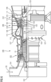
- the Figure 5 shows how Figure 1 a gas turbine engine 100 with the compressor 105 and rotor 103 in cross section.
- air 135 is pumped into the compressor 105, which has a compressor housing 19.
- a rotor bearing 31 of the rotor 103 in the flow direction 11 of the gas turbine engine 100 at the beginning of the compressor 105 and close to the intake housing 104 has a length of at least 370 mm and in particular a maximum length of 500 mm or is designed to be at least 5% longer in the event of an upgrade or revision in order to achieve a lower surface pressure.
- FIG 6 The burner 107' of a gas turbine engine 100 is Figure 1 , 5 or 7 , 8 , 12 or 14 changed.
- the corrosive properties of the fuels, such as gas or oil, that are burned can vary locally.
- the burner system with the burner 107 ( Fig. 1 ) is exposed to the highest temperatures.
- the fuel supply means such as pipes, in particular also of the burner 107', in particular of gas, are at least partially, in particular completely, provided on the inside with a diffusion coating, in particular alitated, i.e. an internal alitation (or chroming, ...) is then used here.
- the internal coating can also be carried out with the products in the installed state.
- Combustion chambers 111 refer to well-known systems such as annular combustion chambers or CANs.
- Figure 7 shows a similar arrangement of a cross section of a gas turbine engine 100 according to Figure 1 , 5 , 6 , 8 , 12 , 14 or 24 , but with a now two-part compressor housing 19, which has an inner compressor housing 19" and an outer compressor housing 19' in the end region of the compressor 105.
- the materials of the compressor housings 19', 19'', especially when they are one-piece, are generally made of the same first material, in particular gray cast iron.
- the inner compressor housing 19" is made as a guide vane carrier from a significantly different second material, in particular from cast steel.
- Different between the first and second materials means that at least one alloying element differs by 10% in weight proportion and/or at least one other alloying element is present or less present and/or a different manufacturing process was used or has a different, distinguishable microstructure.
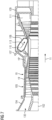
- Figure 8 shows in particular the hot gas channel 111 with its stages I, II, III and especially stage IV.
- Stages I and II are exposed to higher thermal loads than stages III and IV.
- appropriate modifications of the substrate material are used, in particular in the form of directionally solidified alloys (SX, DS) or additional or improved cooling, in particular of the blade tip 415.
- Such a blade 120, 130 preferably has a directionally solidified structure SX, DS in the form of a columnar solidified microstructure, such as alloys with the addition DS in Figure 4 .
- Another type of blade 120, 130 has a single-crystalline microstructure in the substrate such as alloy in Figure 4 with the addition SX or CMSX ....
- the first stage I has a DS structure and, in particular, only the guide vane of stage I.
- the blades 120, 130 have cooling holes on the side surfaces of the blade platform 403, wherein in particular the blade tips 415 are also cooled.
- a ceramic coating (TBC) based on partially stabilized YSZ (yttrium-stabilized zirconia) has a porosity of 1214%.
- Another type of blade 120, 130 has a segmented TBC based on yttrium-stabilized zirconia.
- Another type of blade 120, 130 consists of a directionally solidified structure DS in the substrate, i.e. in the form of a columnar microstructure and with a TBC based on YSZ without segmentation.
- FIG 9 shows a turbine blade 120, 130, in particular starting from Figure 3 , but in which cooling holes 399 are present on the side surfaces 404 of the blade platform 403.
- the cooling holes 399 on the side surfaces 404 can be present on one, two, three or all four side surfaces 404, as required, in one or more cases.
- cooling holes 405 can also be present on the blade tip 415 (only shown schematically). Cooling air holes 418 are also present on the blade 406 in a known manner.
- cooling air holes 399, 405, 418 are only schematic.
- the cooling holes 399, 405, 418, 501 run at an angle other than 90° to the side surface 404 of the blade platform 403 and/or have a diffuser.
- Cooling by cooling air taken from the compressor reduces efficiency, which may be partially compensated by the cooling effect.
- Figure 10 shows a blade tip 415, 500 of a turbine blade 120, in particular of stages I, II.
- the blade tip 500 has two externally extending webs 503, 505 which, when viewed in cross-section, enclose a recess 504.
- the original recess 504 is indicated by dashed lines and is rectangular in cross-section.
- the blade tip 500 has a step-shaped shoulder 507 in the recess 504 which directly adjoins the web 505 on the suction side and thus initially represents additional material in the recess 504.
- a cooling air hole 501 now runs through the shoulder 507 from the interior of the rotor blade 120 in order to better cool the blade tip 500.
- the cooling air hole 501 is preferably aligned with the longitudinal axis 121 of the turbine blade 120.
- the Figure 11 shows a blade carrier 50 with modified cooling air supply.
- Stage IV is attached in the area of this blade carrier 50.
- the front plenum 54 is preferably located behind the stage III rotor blade and in the area above the guide vane IV, as seen in the flow direction 11.
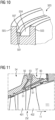
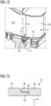
- Figure 12 shows the transition from a last heat shield 155 or combustion chamber brick 155 of the combustion chamber 110 to a guide vane 130 of stage I. It can be seen that a gap 64 is present between the heat shield 155 and the guide vane 130.
- the curve 72 at the flow-side end of the heat shield/combustion chamber brick 155 and the opposite curve 75 of the guide vane 130 of stage I are designed in the same way.
- An overhang or undercut in the heat shield/combustion chamber brick 155 should be avoided, in which dirt could accumulate or erosion could form.
- Figure 13 shows a sealing arrangement 79 of a guide vane carrier 50 ( Fig. 11 ), which leads to lower cooling air consumption.
- the individual elements 81, 83 of the guide vane carrier 79 have a gap 80, which is here labyrinthine or S-shaped.
- the lower cooling air consumption is achieved in that the front element 81 in the flow direction 11 has a first nose 82 and the rear second element 83 in the flow direction 11 has a second nose 85 formed above it, so that an S-shaped gap 80 is formed and the nose 82 of the front element 81 forms part of the hot gas channel 111.
- the opening of the gap in the hot gas channel 111 is located at the rear in the flow direction.
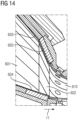
- Figure 14 shows a combustion chamber 110 with combustion chamber stones 601, 604, 610, which lead to a spoiler effect.
- the combustion chamber stones 601, 602 and 603, 605 are arranged in series and in the circumferential direction as seen in the flow direction 11.
- modified combustion chamber stones 603, 605; 604 are present at the end, with further such combustion chamber stones being arranged in the circumferential direction around the rotation axis 102.
- the modified combustion chamber bricks 603, 604, 605, preferably made of solid ceramic, preferably in the two last rows of the combustion chamber 110 before the inlet or transition to the guide vanes 130 or first row of rotor blades 120 of stage I, as seen in the flow direction 11, are designed to be increasingly thicker in the flow direction 11, so that a spoiler effect Near the rotor hub, preferably only one combustion chamber brick 604 is designed in a spoiler shape, whereas further radially away at the outer end of the combustion chamber 110, at least the penultimate and last row of combustion chamber bricks 603, 605, viewed together, have a gradual increase in thickness in the direction of flow.
- This spoiler effect reduces erosion and also narrows the hot gas flow, which also increases efficiency.
- Figure 15 shows a combustion chamber brick 155 with a side surface 35, whereas Figures 16, 17 Cross-sectional views of the Figure 15 are.
- Figure 15 shows the side surface 35 of a combustion chamber brick 155 as used in a combustion chamber 110, wherein a side surface 35 has two elongated recesses 40, 40' in which a holder engages from the rear and a corresponding through opening 42 on the rear side 43 of the combustion chamber brick 155, which is opposite the top side 44.
- an undercut 41 is present along the side surface with the recesses 40.
- Figure 16 is a section through two combustion chamber stones placed next to each other according to Figure 15 along the through opening 42', 42", whereas in Figure 17 a gap between two combustion chamber bricks 155 according to Figure 15 outside the opening 42 or elongated recess 40.
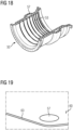
- Figure 18 shows a lower turbine housing part 550 with the guide vane recesses 553 and channel 557 in the contact surface 600 for the other, upper housing half.
- one or more additional recesses 630 and a seal are introduced to reduce leakage in this area ( Fig. 19 ).
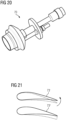
- Figure 20 shows a burner 70 having a swirler in which air and fuel are mixed together.
- Two different guide vanes 73', 73" of the swirler are in the Figure 21 and show a different, modified flatter angle (73') from the first position to a second position and/or a torsion of the guide vane 73" along a trailing edge to achieve better swirl.
- the dashed line indicates the original position of the swirler guide vane, whereas the dashed line for guide vane 73" indicates how it is twisted along its longitudinal axis, which runs parallel to the leading edge.
- Gas turbines can be operated alone to power a generator, but often also in combination with steam turbines in a combined cycle plant.
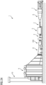
- combustion stability and dynamics also have a very high influence on the service life of the system, so a control system 90 is installed here, which registers the combustion dynamics and acceleration ( Fig 23 ).
- Some of the service measures can be carried out together because the measures can be carried out more easily together and, if necessary, in parallel.
- Some measures can be offered to the plant operator free of charge and can be used to extend or even skip the next service interval or to reduce operating costs by increasing efficiency/higher efficiency, in which the service provider is involved.
- service contracts are often concluded, which offer the operator of the energy conversion plant a service maintenance contract, which includes a certain mileage (service life) being guaranteed for certain performance characteristics with predetermined service intervals.
- new burners with alumina coating can be used, so that servicing of the burner components is not necessary at the next or subsequent interval. This avoids downtime.
- a service measure can be used to extend the service life or to bring forward a service measure so that the next service measure is significantly shortened, because measures such as bearing removal, turbine blade removal, replacement of combustion chamber bricks, changes to the housing, etc. involve different maintenance times.
- the flexible refurbishment includes enhanced remote monitoring and diagnostic capabilities as part of the Omnivise Digital Services portfolio, as well as spare parts deliveries, scheduled maintenance and performance guarantees during the plant's operating period. With its high efficiency in part-load operation and high operational flexibility, the combined cycle gas and steam power plant and its associated services will complement the fluctuating renewable energy sources in the region as part of this flexible refurbishment.
- the long-term, flexible service goes one step further and offers a maintenance program that is individually tailored to specific needs and requirements.
Landscapes
- Engineering & Computer Science (AREA)
- Mechanical Engineering (AREA)
- General Engineering & Computer Science (AREA)
- Chemical & Material Sciences (AREA)
- Materials Engineering (AREA)
- Ceramic Engineering (AREA)
- Turbine Rotor Nozzle Sealing (AREA)
- Supply And Distribution Of Alternating Current (AREA)
- Diaphragms For Electromechanical Transducers (AREA)
Applications Claiming Priority (3)
| Application Number | Priority Date | Filing Date | Title |
|---|---|---|---|
| DE102019207479.0A DE102019207479A1 (de) | 2019-05-22 | 2019-05-22 | Verfahren zur Durchführung von Servicemaßnahmen an einer Energieumwandlungsanlage und Energieumwandlungsanlage |
| PCT/EP2020/061141 WO2020233925A1 (fr) | 2019-05-22 | 2020-04-22 | Procédé pour entreprendre des mesures de service au niveau d'une installation de conversion d'énergie et installation de conversion d'énergie |
| EP20725415.2A EP3947915A1 (fr) | 2019-05-22 | 2020-04-22 | Procédé pour entreprendre des mesures de service au niveau d'une installation de conversion d'énergie et installation de conversion d'énergie |
Related Parent Applications (1)
| Application Number | Title | Priority Date | Filing Date |
|---|---|---|---|
| EP20725415.2A Division EP3947915A1 (fr) | 2019-05-22 | 2020-04-22 | Procédé pour entreprendre des mesures de service au niveau d'une installation de conversion d'énergie et installation de conversion d'énergie |
Publications (2)
| Publication Number | Publication Date |
|---|---|
| EP4438858A2 true EP4438858A2 (fr) | 2024-10-02 |
| EP4438858A3 EP4438858A3 (fr) | 2024-12-18 |
Family
ID=70681764
Family Applications (4)
| Application Number | Title | Priority Date | Filing Date |
|---|---|---|---|
| EP20725415.2A Pending EP3947915A1 (fr) | 2019-05-22 | 2020-04-22 | Procédé pour entreprendre des mesures de service au niveau d'une installation de conversion d'énergie et installation de conversion d'énergie |
| EP24198900.3A Pending EP4455452A3 (fr) | 2019-05-22 | 2020-04-22 | Procédé pour entreprendre des mesures de service au niveau d'une installation de conversion d'énergie et installation de conversion d'énergie |
| EP25207485.1A Pending EP4653667A3 (fr) | 2019-05-22 | 2020-04-22 | Procédé pour effectuer des mesures de service sur une installation de conversion d'énergie et installation de conversion d'énergie |
| EP24194316.6A Pending EP4438858A3 (fr) | 2019-05-22 | 2020-04-22 | Procédé pour effectuer des mesures de service sur une installation de conversion d'énergie et installation de conversion d'énergie |
Family Applications Before (3)
| Application Number | Title | Priority Date | Filing Date |
|---|---|---|---|
| EP20725415.2A Pending EP3947915A1 (fr) | 2019-05-22 | 2020-04-22 | Procédé pour entreprendre des mesures de service au niveau d'une installation de conversion d'énergie et installation de conversion d'énergie |
| EP24198900.3A Pending EP4455452A3 (fr) | 2019-05-22 | 2020-04-22 | Procédé pour entreprendre des mesures de service au niveau d'une installation de conversion d'énergie et installation de conversion d'énergie |
| EP25207485.1A Pending EP4653667A3 (fr) | 2019-05-22 | 2020-04-22 | Procédé pour effectuer des mesures de service sur une installation de conversion d'énergie et installation de conversion d'énergie |
Country Status (4)
| Country | Link |
|---|---|
| US (2) | US12055063B2 (fr) |
| EP (4) | EP3947915A1 (fr) |
| DE (1) | DE102019207479A1 (fr) |
| WO (1) | WO2020233925A1 (fr) |
Families Citing this family (1)
| Publication number | Priority date | Publication date | Assignee | Title |
|---|---|---|---|---|
| DE102019207479A1 (de) * | 2019-05-22 | 2020-11-26 | Siemens Aktiengesellschaft | Verfahren zur Durchführung von Servicemaßnahmen an einer Energieumwandlungsanlage und Energieumwandlungsanlage |
Citations (10)
| Publication number | Priority date | Publication date | Assignee | Title |
|---|---|---|---|---|
| EP0486489B1 (fr) | 1989-08-10 | 1994-11-02 | Siemens Aktiengesellschaft | Revetement anticorrosion resistant aux temperatures elevees, notamment pour elements de turbines a gaz |
| EP0412397B1 (fr) | 1989-08-10 | 1998-03-25 | Siemens Aktiengesellschaft | Revêtement protecteur contenant du rhénium possédant une résistance plus grande à la corrosion et l'oxydation |
| EP0892090A1 (fr) | 1997-02-24 | 1999-01-20 | Sulzer Innotec Ag | Procédé de fabrication de structure smonocristallines |
| EP0786017B1 (fr) | 1994-10-14 | 1999-03-24 | Siemens Aktiengesellschaft | Couche de protection de pieces contre la corrosion, l'oxydation et les contraintes thermiques excessives, et son procede de production |
| WO1999067435A1 (fr) | 1998-06-23 | 1999-12-29 | Siemens Aktiengesellschaft | Alliage a solidification directionnelle a resistance transversale a la rupture amelioree |
| US6024792A (en) | 1997-02-24 | 2000-02-15 | Sulzer Innotec Ag | Method for producing monocrystalline structures |
| WO2000044949A1 (fr) | 1999-01-28 | 2000-08-03 | Siemens Aktiengesellschaft | Superalliage a base de nickel presentant une bonne usinabilite |
| EP1306454A1 (fr) | 2001-10-24 | 2003-05-02 | Siemens Aktiengesellschaft | Revêtement protecteur contenant du rhénium pour la protection d'un élément contre l'oxydation et la corrosion aux températures élevées |
| EP1319729A1 (fr) | 2001-12-13 | 2003-06-18 | Siemens Aktiengesellschaft | Pièce résistante à des températures élevées réalisé en superalliage polycristallin ou monocristallin à base de nickel |
| EP1204776B1 (fr) | 1999-07-29 | 2004-06-02 | Siemens Aktiengesellschaft | Piece resistant a des temperatures elevees et son procede de production |
Family Cites Families (20)
| Publication number | Priority date | Publication date | Assignee | Title |
|---|---|---|---|---|
| US1988217A (en) * | 1934-06-15 | 1935-01-15 | Bertram J Sayles | Calorized steel article |
| AU4451700A (en) * | 1999-04-09 | 2000-11-14 | Mcdermott Technology, Inc. | Tunneled multi-blade swirler/gas injector for a burner |
| US6636813B1 (en) * | 1999-09-27 | 2003-10-21 | Hitchi, Ltd. | Service life management system for high-temperature part of gas turbine |
| DE10163474A1 (de) * | 2001-12-21 | 2003-07-10 | Siemens Ag | Verfahren und Vorrichtung zur Behandlung und/oder Reformierung von gasförmigen Brennstoffen und zugehörige Anwendung |
| JP2004145496A (ja) * | 2002-10-23 | 2004-05-20 | Hitachi Ltd | 機器設備の保守支援方法 |
| DE10319019B4 (de) * | 2003-04-27 | 2006-03-30 | Mtu Aero Engines Gmbh | Verfahren zur Wartung, insbesondere Reparatur, von Gasturbinen |
| US7094444B2 (en) * | 2003-11-13 | 2006-08-22 | General Electric Company | Method for repairing coated components using NiAl bond coats |
| EP1591549B1 (fr) * | 2004-04-28 | 2010-03-24 | Alstom Technology Ltd | Procédé de réparation d'une dégradation locale d'un revêtement de barrière thermique d'une pièce |
| EP1666625A1 (fr) * | 2004-12-01 | 2006-06-07 | Siemens Aktiengesellschaft | Procédé de revêtement d'un composant a l'interieur d'un aparat |
| EP1707650A1 (fr) * | 2005-03-31 | 2006-10-04 | Siemens Aktiengesellschaft | Matrice et système de couches |
| EP1843007A1 (fr) * | 2006-04-06 | 2007-10-10 | Siemens Aktiengesellschaft | Aube de turbine avec élément de fermeture séparé |
| DE102008051384B3 (de) * | 2008-10-11 | 2010-02-11 | Technische Universität Dresden | Solarhybridbetriebenes Gas- und Dampfkraftwerk |
| US8328506B2 (en) * | 2008-12-04 | 2012-12-11 | General Electric Company | Optimized turbocharger bearing system |
| US9102015B2 (en) * | 2013-03-14 | 2015-08-11 | Siemens Energy, Inc | Method and apparatus for fabrication and repair of thermal barriers |
| DE102013223327A1 (de) * | 2013-11-15 | 2015-05-21 | Siemens Aktiengesellschaft | Poröses keramisches Schichtsystem |
| DE102014215647A1 (de) * | 2014-08-07 | 2016-02-11 | Siemens Aktiengesellschaft | Kraftwerk zur Erzeugung elektrischer Energie mit zwei Generatorvorrichtungen |
| JP6816949B2 (ja) * | 2014-11-26 | 2021-01-20 | ゼネラル・エレクトリック・カンパニイ | 発電プラント発電ユニットの制御を強化するための方法 |
| US20170009584A1 (en) * | 2015-07-09 | 2017-01-12 | General Electric Company | Systems and Methods for Turbine Blade Repair |
| DE102016200916A1 (de) * | 2016-01-22 | 2017-07-27 | Ferdinand Reif | Gasturbineneinsatz bei Oxidationsprozessen |
| DE102019207479A1 (de) * | 2019-05-22 | 2020-11-26 | Siemens Aktiengesellschaft | Verfahren zur Durchführung von Servicemaßnahmen an einer Energieumwandlungsanlage und Energieumwandlungsanlage |
-
2019
- 2019-05-22 DE DE102019207479.0A patent/DE102019207479A1/de not_active Withdrawn
-
2020
- 2020-04-22 EP EP20725415.2A patent/EP3947915A1/fr active Pending
- 2020-04-22 EP EP24198900.3A patent/EP4455452A3/fr active Pending
- 2020-04-22 EP EP25207485.1A patent/EP4653667A3/fr active Pending
- 2020-04-22 WO PCT/EP2020/061141 patent/WO2020233925A1/fr not_active Ceased
- 2020-04-22 US US17/609,378 patent/US12055063B2/en active Active
- 2020-04-22 EP EP24194316.6A patent/EP4438858A3/fr active Pending
-
2024
- 2024-08-03 US US18/793,761 patent/US20240392684A1/en active Pending
Patent Citations (10)
| Publication number | Priority date | Publication date | Assignee | Title |
|---|---|---|---|---|
| EP0486489B1 (fr) | 1989-08-10 | 1994-11-02 | Siemens Aktiengesellschaft | Revetement anticorrosion resistant aux temperatures elevees, notamment pour elements de turbines a gaz |
| EP0412397B1 (fr) | 1989-08-10 | 1998-03-25 | Siemens Aktiengesellschaft | Revêtement protecteur contenant du rhénium possédant une résistance plus grande à la corrosion et l'oxydation |
| EP0786017B1 (fr) | 1994-10-14 | 1999-03-24 | Siemens Aktiengesellschaft | Couche de protection de pieces contre la corrosion, l'oxydation et les contraintes thermiques excessives, et son procede de production |
| EP0892090A1 (fr) | 1997-02-24 | 1999-01-20 | Sulzer Innotec Ag | Procédé de fabrication de structure smonocristallines |
| US6024792A (en) | 1997-02-24 | 2000-02-15 | Sulzer Innotec Ag | Method for producing monocrystalline structures |
| WO1999067435A1 (fr) | 1998-06-23 | 1999-12-29 | Siemens Aktiengesellschaft | Alliage a solidification directionnelle a resistance transversale a la rupture amelioree |
| WO2000044949A1 (fr) | 1999-01-28 | 2000-08-03 | Siemens Aktiengesellschaft | Superalliage a base de nickel presentant une bonne usinabilite |
| EP1204776B1 (fr) | 1999-07-29 | 2004-06-02 | Siemens Aktiengesellschaft | Piece resistant a des temperatures elevees et son procede de production |
| EP1306454A1 (fr) | 2001-10-24 | 2003-05-02 | Siemens Aktiengesellschaft | Revêtement protecteur contenant du rhénium pour la protection d'un élément contre l'oxydation et la corrosion aux températures élevées |
| EP1319729A1 (fr) | 2001-12-13 | 2003-06-18 | Siemens Aktiengesellschaft | Pièce résistante à des températures élevées réalisé en superalliage polycristallin ou monocristallin à base de nickel |
Also Published As
| Publication number | Publication date |
|---|---|
| US12055063B2 (en) | 2024-08-06 |
| EP4455452A2 (fr) | 2024-10-30 |
| EP4653667A3 (fr) | 2026-02-25 |
| EP4438858A3 (fr) | 2024-12-18 |
| EP3947915A1 (fr) | 2022-02-09 |
| EP4455452A3 (fr) | 2025-01-22 |
| DE102019207479A1 (de) | 2020-11-26 |
| US20220316339A1 (en) | 2022-10-06 |
| EP4653667A2 (fr) | 2025-11-26 |
| WO2020233925A1 (fr) | 2020-11-26 |
| US20240392684A1 (en) | 2024-11-28 |
Similar Documents
| Publication | Publication Date | Title |
|---|---|---|
| EP2458025B1 (fr) | Alliage, couche de protection et composant | |
| WO2006061267A1 (fr) | Systeme stratifie, utilisation et procede de realisation d'un systeme stratifie | |
| EP2733310A1 (fr) | Surface modifiée autour d'un trou | |
| EP1999298A2 (fr) | Matrice et système de couches comprenant des particules non stoechiométriques | |
| EP2394027A1 (fr) | Elément de turbine présentant une couche de protection pouvant être facilement supprimée, jeu d'éléments de turbine, turbine et procédé de protection d'un élément de turbine | |
| WO2010078994A1 (fr) | Procédé pour recouvrir un composant pourvu de trous de refroidissement pelliculaire et composant | |
| EP2882939A1 (fr) | Procédé de reconditionnement d'une aube de turbine à gaz ainsi que turbine à gaz pourvue d'une telle aube | |
| EP2230041A2 (fr) | Procédé de fabrication d'un trou | |
| EP1835045A1 (fr) | Procédé d'obtention d'une pièce revêtue | |
| EP4438858A2 (fr) | Procédé pour effectuer des mesures de service sur une installation de conversion d'énergie et installation de conversion d'énergie | |
| EP1816222A1 (fr) | Système de revêtements de couches métalliques protectrices à double couche | |
| WO2008049460A1 (fr) | PROCÉDÉ POUR RÉGLER LA RUGOSITÉ de surface LORS D'UNE OPÉRATION DE REVÊTEMENT À BASSE TEMPÉRATURE, ET ÉLÉMENT DE CONSTRUCTION | |
| WO2006079441A1 (fr) | Composant presentant un meplat dans un alesage | |
| WO2006103125A1 (fr) | Systeme de couches et procede pour realiser un systeme de couches | |
| EP1681374B1 (fr) | Système de revêtement comprenant une couche barrière et procédé de fabrication | |
| EP1586675B1 (fr) | Procédé de revêtement de l'intérieur d'un corps creux | |
| EP2102379B1 (fr) | Procédé d'utilisation d'une turbine qui présente un oxyde sur une couche métallique et une turbine | |
| EP2586985A1 (fr) | Surface dotée d'un renfoncement formé de manière spécifique et composant | |
| WO2007080058A1 (fr) | Composant compact en ceramique, couche ceramique a tres forte porosite, utilisation de cette couche et composant la contenant | |
| EP2086715A1 (fr) | Poudre de brasage composite constituée d'une âme et d'une enveloppe métallique, pour le brasage d'éléments de turbine | |
| WO2007144217A1 (fr) | Procédé d'application d'un matériau sur un composant | |
| EP1808236A1 (fr) | Procédé pour masquer des trous de refroidissement, en particulier d'aubes de turbine | |
| WO2007085512A1 (fr) | Procede de fabrication d'un composant dote de trous | |
| EP1930115A1 (fr) | Fil, son utilisation et procédé de soudage | |
| WO2006053838A2 (fr) | Procede de coulee et piece coulee |
Legal Events
| Date | Code | Title | Description |
|---|---|---|---|
| PUAI | Public reference made under article 153(3) epc to a published international application that has entered the european phase |
Free format text: ORIGINAL CODE: 0009012 |
|
| STAA | Information on the status of an ep patent application or granted ep patent |
Free format text: STATUS: REQUEST FOR EXAMINATION WAS MADE |
|
| 17P | Request for examination filed |
Effective date: 20240816 |
|
| AC | Divisional application: reference to earlier application |
Ref document number: 3947915 Country of ref document: EP Kind code of ref document: P |
|
| AK | Designated contracting states |
Kind code of ref document: A2 Designated state(s): AL AT BE BG CH CY CZ DE DK EE ES FI FR GB GR HR HU IE IS IT LI LT LU LV MC MK MT NL NO PL PT RO RS SE SI SK SM TR |
|
| REG | Reference to a national code |
Ref country code: DE Ref legal event code: R079 Free format text: PREVIOUS MAIN CLASS: F01D0005280000 Ipc: F01D0005000000 |
|
| PUAL | Search report despatched |
Free format text: ORIGINAL CODE: 0009013 |
|
| AK | Designated contracting states |
Kind code of ref document: A3 Designated state(s): AL AT BE BG CH CY CZ DE DK EE ES FI FR GB GR HR HU IE IS IT LI LT LU LV MC MK MT NL NO PL PT RO RS SE SI SK SM TR |
|
| RIC1 | Information provided on ipc code assigned before grant |
Ipc: F01D 5/28 20060101ALI20241112BHEP Ipc: F01D 5/00 20060101AFI20241112BHEP |