EP4438899A2 - Pompe à membrane - Google Patents
Pompe à membrane Download PDFInfo
- Publication number
- EP4438899A2 EP4438899A2 EP24175473.8A EP24175473A EP4438899A2 EP 4438899 A2 EP4438899 A2 EP 4438899A2 EP 24175473 A EP24175473 A EP 24175473A EP 4438899 A2 EP4438899 A2 EP 4438899A2
- Authority
- EP
- European Patent Office
- Prior art keywords
- outlet
- chamber
- inlet
- pump
- valve
- Prior art date
- Legal status (The legal status is an assumption and is not a legal conclusion. Google has not performed a legal analysis and makes no representation as to the accuracy of the status listed.)
- Pending
Links
Images



Classifications
-
- F—MECHANICAL ENGINEERING; LIGHTING; HEATING; WEAPONS; BLASTING
- F04—POSITIVE - DISPLACEMENT MACHINES FOR LIQUIDS; PUMPS FOR LIQUIDS OR ELASTIC FLUIDS
- F04B—POSITIVE-DISPLACEMENT MACHINES FOR LIQUIDS; PUMPS
- F04B43/00—Machines, pumps, or pumping installations having flexible working members
- F04B43/0009—Special features
-
- F—MECHANICAL ENGINEERING; LIGHTING; HEATING; WEAPONS; BLASTING
- F04—POSITIVE - DISPLACEMENT MACHINES FOR LIQUIDS; PUMPS FOR LIQUIDS OR ELASTIC FLUIDS
- F04B—POSITIVE-DISPLACEMENT MACHINES FOR LIQUIDS; PUMPS
- F04B43/00—Machines, pumps, or pumping installations having flexible working members
- F04B43/0009—Special features
- F04B43/0045—Special features with a number of independent working chambers which are actuated successively by one mechanism
-
- F—MECHANICAL ENGINEERING; LIGHTING; HEATING; WEAPONS; BLASTING
- F04—POSITIVE - DISPLACEMENT MACHINES FOR LIQUIDS; PUMPS FOR LIQUIDS OR ELASTIC FLUIDS
- F04B—POSITIVE-DISPLACEMENT MACHINES FOR LIQUIDS; PUMPS
- F04B43/00—Machines, pumps, or pumping installations having flexible working members
- F04B43/02—Machines, pumps, or pumping installations having flexible working members having plate-like flexible members, e.g. diaphragms
- F04B43/025—Machines, pumps, or pumping installations having flexible working members having plate-like flexible members, e.g. diaphragms two or more plate-like pumping members in parallel
- F04B43/026—Machines, pumps, or pumping installations having flexible working members having plate-like flexible members, e.g. diaphragms two or more plate-like pumping members in parallel each plate-like pumping flexible member working in its own pumping chamber
-
- F—MECHANICAL ENGINEERING; LIGHTING; HEATING; WEAPONS; BLASTING
- F04—POSITIVE - DISPLACEMENT MACHINES FOR LIQUIDS; PUMPS FOR LIQUIDS OR ELASTIC FLUIDS
- F04B—POSITIVE-DISPLACEMENT MACHINES FOR LIQUIDS; PUMPS
- F04B53/00—Component parts, details or accessories not provided for in, or of interest apart from, groups F04B1/00 - F04B23/00 or F04B39/00 - F04B47/00
- F04B53/10—Valves; Arrangement of valves
- F04B53/1037—Flap valves
- F04B53/1047—Flap valves the valve being formed by one or more flexible elements
- F04B53/106—Flap valves the valve being formed by one or more flexible elements the valve being a membrane
- F04B53/1065—Flap valves the valve being formed by one or more flexible elements the valve being a membrane fixed at its centre
-
- F—MECHANICAL ENGINEERING; LIGHTING; HEATING; WEAPONS; BLASTING
- F04—POSITIVE - DISPLACEMENT MACHINES FOR LIQUIDS; PUMPS FOR LIQUIDS OR ELASTIC FLUIDS
- F04B—POSITIVE-DISPLACEMENT MACHINES FOR LIQUIDS; PUMPS
- F04B53/00—Component parts, details or accessories not provided for in, or of interest apart from, groups F04B1/00 - F04B23/00 or F04B39/00 - F04B47/00
- F04B53/10—Valves; Arrangement of valves
- F04B53/1037—Flap valves
- F04B53/1047—Flap valves the valve being formed by one or more flexible elements
- F04B53/106—Flap valves the valve being formed by one or more flexible elements the valve being a membrane
- F04B53/1067—Flap valves the valve being formed by one or more flexible elements the valve being a membrane fixed at its whole periphery and with an opening at its centre
-
- F—MECHANICAL ENGINEERING; LIGHTING; HEATING; WEAPONS; BLASTING
- F04—POSITIVE - DISPLACEMENT MACHINES FOR LIQUIDS; PUMPS FOR LIQUIDS OR ELASTIC FLUIDS
- F04B—POSITIVE-DISPLACEMENT MACHINES FOR LIQUIDS; PUMPS
- F04B53/00—Component parts, details or accessories not provided for in, or of interest apart from, groups F04B1/00 - F04B23/00 or F04B39/00 - F04B47/00
- F04B53/10—Valves; Arrangement of valves
- F04B53/1072—Valves; Arrangement of valves the valve being an elastic body, the length thereof changing in the opening direction
-
- F—MECHANICAL ENGINEERING; LIGHTING; HEATING; WEAPONS; BLASTING
- F04—POSITIVE - DISPLACEMENT MACHINES FOR LIQUIDS; PUMPS FOR LIQUIDS OR ELASTIC FLUIDS
- F04B—POSITIVE-DISPLACEMENT MACHINES FOR LIQUIDS; PUMPS
- F04B45/00—Pumps or pumping installations having flexible working members and specially adapted for elastic fluids
- F04B45/04—Pumps or pumping installations having flexible working members and specially adapted for elastic fluids having plate-like flexible members, e.g. diaphragms
- F04B45/043—Pumps or pumping installations having flexible working members and specially adapted for elastic fluids having plate-like flexible members, e.g. diaphragms two or more plate-like pumping flexible members in parallel
Definitions
- the invention relates to a diaphragm pump with a pump chamber, wherein the pump chamber is connected to an inlet chamber via an inlet channel and to an outlet chamber via an outlet channel.
- Diaphragm pumps which have a pump head which is essentially connected to a drive.
- the pump head has several, for example four, pump chambers, each of which is sealed from a drive chamber by means of a pump diaphragm.
- the respective pump diaphragm is connected to a wobble plate arranged in the drive chamber via an associated pump element.
- a wobble movement of the wobble plate causes the pump diaphragm to be set into a wobbling axial periodic pumping movement.
- the wobble plate sits on a drive pin of a drive shaft connected to the drive.
- the drive pin is inclined relative to the longitudinal axis of the drive shaft and is connected to the wobble plate via a ball bearing.
- An outlet chamber is arranged centrally and an inlet chamber is arranged concentrically to the outlet chamber around the outlet chamber.
- the inlet chamber is arranged centrally and the outlet chamber is arranged concentrically to the inlet chamber.
- the outlet chamber has an outlet channel in its lower region in the vertical direction, wherein a valve plate having the pump chambers and valves is arranged between an intermediate plate part having the chambers and a membrane carrier part carrying the pump diaphragms, wherein an inlet valve plate having the inlet valves is arranged in front of the inlet chamber of the intermediate plate part in a shoulder of the valve plate towards the pump chambers.
- Such pumps are used in particular in the chemical, pharmaceutical and biotechnology sectors, where the media to be pumped are sometimes very expensive, so it is desirable that after the pumping process there is as little or as little residual volume of the pumped medium as possible in the diaphragm pump. Furthermore, the complete filling of such diaphragm pumps with the fluid without air inclusions is advantageous for the pumping performance.
- a key feature of the known diaphragm pumps which have generally proven themselves, is that they have a central inlet chamber, which means that a relatively large residual volume of the pumped medium remains in the inlet chamber after the pumping process has ended, due to the essentially concentrically arranged external outlet chamber. Furthermore, air usually remains in the upper pump chambers of the pump, which usually has a detrimental effect on the delivery stability (pulsation) as well as the pumping performance.
- a disadvantage of the DE 10 2008 035 592 B4 known diaphragm pump is that air remains at least in the upper pump chambers of the diaphragm pump.
- the object of the present invention is therefore to improve the known diaphragm pumps with regard to the residual emptying and/or the venting of the pump chambers.
- the invention is based on the basic idea that the outlet opening of the outlet valve surrounds the inlet opening of the inlet valve or the inlet opening surrounds the outlet opening.
- the outlet valve opening surrounding the inlet valve opening it is possible for any air present in the pump chamber to flow from the pump chamber into the outlet chamber through the sections of the outlet valve opening provided above the inlet valve opening and not - as with some prior art diaphragm pumps - be trapped in the upper area of the pump chamber.
- the outlet valve opening surrounding the inlet valve opening it is also possible for the fluid to be pumped in the lower area of a pump chamber to flow into the outlet chamber through the area of the outlet opening provided below the inlet opening, thus achieving good residual emptying.
- the diaphragm pump With the diaphragm pump according to the invention, it is therefore possible for the diaphragm pump to empty and/or vent itself to a large extent, in particular automatically. In addition to improved flow distribution, a small size is also possible, which allows the amount of fluid to be pumped in the diaphragm pump to be significantly reduced. It also allows both the outlet chamber and the inlet chamber to be arranged centrally. Together with an outlet channel arranged in the lower area in a preferred embodiment, both the inlet chamber and the outlet chamber can now run practically completely empty.
- the diaphragm pump has a pump chamber, preferably two and particularly preferably three, four or more pump chambers.
- the volume of this can be changed particularly preferably cyclically, in particular periodically, by an external force.
- a diaphragm which is preferably made of an elastic material, for example plastic, rubber, elastomer, silicone or an equivalent material, which can in particular also comprise composite materials for increased stability and service life.
- the pump chamber can be dimensioned with regard to the maximum volume of the pump chamber to be maintained so that this maximum volume corresponds exactly to the volume of fluid to be pumped within a pump stroke.
- significantly larger pump chambers are also conceivable, which improve, for example, the flow behavior, the efficiency of the diaphragm pump or the production costs.
- a pump chamber has at least one inlet and at least one outlet valve.
- the inlet valve has an inlet opening that can be closed by an inlet valve body and the outlet valve has an outlet opening that can be closed by an outlet valve body.
- the respective valve body can in particular be formed by an elastic membrane, which generally at least partially releases the valve opening assigned to the valve body when a suitable pressure difference is present.
- Metals are also possible materials for the valve body, for example, but plastic, rubber, elastomer, silicone or an equivalent material are also conceivable, which in particular also includes composite materials.
- valve body When a pressure difference is present in the opposite direction, the valve body closes the valve opening and/or a spring element is provided that acts on the valve body and preloads it into the closed position when it is outside the closed position in which the valve body closes the valve opening.
- a membrane is understood here to be a preferably flat plate, which usually has elastic and/or springy properties, even if only in sections, for example through a flexible edge section.
- a valve control can control the opening and closing of the valves or influence an optimization of the pumping process.
- the outlet opening surrounds the inlet opening or the inlet opening surrounds the outlet opening.
- the inlet valve and/or the outlet valve is an umbrella valve.
- An umbrella valve is understood to mean a valve in which the valve body is formed by an umbrella.
- An inlet chamber serves to hold the fluid.
- the inlet opening can be formed directly in a wall of the inlet chamber. This enables a compact design of the diaphragm pump, particularly if, in a further preferred embodiment, the inlet opening opens directly into the pump chamber. In a preferred embodiment, however, an inlet channel is provided between the inlet chamber and pump chamber, which connects the inlet chamber to the pump chamber. This creates the possibility of designing the position of the inlet chamber within the diaphragm pump relative to the pump chamber more freely.
- An outlet chamber is used to collect and bundle the pumped fluid, in particular for forwarding it to a central outlet of the diaphragm pump, in particular when there are several pump chambers and/or outlet valves.
- the outlet opening can be formed directly in a wall of the outlet chamber. This enables a compact design of the diaphragm pump, in particular if, in a further preferred embodiment, the outlet opening opens directly into the pump chamber.
- an outlet channel is provided between the outlet chamber and pump chamber, which connects the outlet chamber to the pump chamber. This creates the possibility of designing the position of the outlet chamber within the diaphragm pump relative to the pump chamber more freely.
- the outlet opening surrounds the inlet opening
- preferred embodiments are conceivable in which the outlet opening is formed by a single ring-shaped opening.
- Ring-shaped is understood to mean that, starting from a center point which the opening surrounds, a section of the opening is provided in each radial direction.
- the term “ring-shaped” is not restricted to the description of circular ring-shaped openings.
- the shape of the free space forming the opening is defined in particular by the shape of the walls delimiting the free space. In the case of a circular ring-shaped opening, the opening is delimited, for example, by a first circular ring-shaped wall and a second circular ring-shaped wall arranged opposite the first circular ring-shaped wall.
- the shape of the free space forming the opening is delimited by an outer wall and an inner wall, viewed in the radial direction from a center point which the opening surrounds.
- the outer wall and the inner wall have the same geometric shape.
- the inner Wall and the outer wall are designed concentrically to one another.
- both the outer wall and the inner wall are the walls of a circle, an ellipse, a rectangle, in particular a square or a triangle.
- the distance between the inner wall and the outer wall is preferably constant at every point in the circumferential direction of the outlet opening. This is particularly useful when the outer wall and the inner wall have the same geometric shape.
- embodiments are also conceivable in which the distance between the inner wall and the outer wall is not constant at every point in the circumferential direction of the outlet opening.
- This can be achieved in particular by the fact that, in a preferred embodiment, the outer wall and the inner wall do not have the same geometric shape or have the same geometric shape but are not concentric with each other.
- the outlet opening of the outlet valve is formed by at least two outlet opening sections which are separate from one another and which surround the inlet opening.
- the term "outlet opening” therefore does not describe a single opening but is also used as a representative of a sum of individual openings which are separated from one another.
- the outlet opening is segmented into several outlet opening sections.
- the outlet opening sections are particularly preferably arranged in a ring-like manner around the inlet opening.
- the outlet opening can be formed by an arcuate outlet opening section above the inlet opening and/or an arcuate outlet opening section below the inlet opening, while in a particularly preferred embodiment no outlet opening sections are provided to the side of the inlet opening.
- the association of the outlet opening sections with an outlet valve is achieved in a preferred embodiment in that the outlet opening sections are closed by a common valve body.
- the inlet opening is formed by a single opening that is not divided into outlet opening sections.
- inlet opening sections that are spatially arranged within an envelope enclosing the outlet opening sections.
- a collection of circular inlet opening sections arranged side by side may be provided.
- the inlet opening surrounds the outlet opening
- preferred embodiments are conceivable in which the inlet opening is formed by a single ring-shaped opening.
- Ring-shaped is understood to mean that, starting from a center point which the opening surrounds, a section of the opening is provided in each radial direction.
- the term “ring-shaped” is not restricted to the description of circular ring-shaped openings.
- the shape of the free space forming the opening is defined in particular by the shape of the walls delimiting the free space. In the case of a circular ring-shaped opening, the opening is delimited, for example, by a first circular ring-shaped wall and a second circular ring-shaped wall arranged opposite the first circular ring-shaped wall.
- the shape of the free space forming the opening is delimited by an outer wall and an inner wall, viewed in the radial direction from a center point which the opening surrounds.
- the outer wall and the inner wall have the same geometric shape.
- the inner wall and the outer wall are designed to be concentric with one another.
- both the outer wall and the inner wall are the walls of a circle, an ellipse, a rectangle, in particular a square or a triangle.
- the distance between the inner wall and the outer wall is constant at every point in the circumferential direction of the inlet opening. This is particularly useful when the outer wall and the inner wall have the same geometric shape.
- embodiments are also conceivable in which the distance between the inner wall and the outer wall is not constant at every point in the circumferential direction of the inlet opening. It can therefore be advantageous to choose a larger distance between the inner wall and the outer wall in the upper and/or lower areas of the inlet opening than in the lateral areas in order to offer the fluid flowing through the inlet opening a particularly large amount of space, in particular in the upper and/or lower areas.
- This can be achieved in particular by the fact that, in a preferred embodiment, the outer wall and the inner wall do not have the same geometric shape or have the same geometric shape but are not concentric with each other.
- the inlet opening of the inlet valve is formed by at least two separate inlet opening sections which surround the inlet opening.
- the term "inlet opening" describes in the context of the In the present description, therefore, not a single opening is used but is also used as a representative of a sum of individual openings that are separated from one another.
- the inlet opening is segmented into several inlet opening sections. The inlet opening sections are particularly preferably arranged in a ring around the inlet opening.
- the inlet opening can be formed by an arcuate inlet opening section above the outlet opening and/or an arcuate inlet opening section below the outlet opening, while in a particularly preferred embodiment no inlet opening sections are provided to the side of the outlet opening.
- the association of the inlet opening section with an inlet valve is achieved in a preferred embodiment in that the inlet opening sections are closed by a common valve body.
- the outlet opening is formed by a single opening that is not divided into outlet opening sections.
- the inlet chamber and the outlet chamber are designed around a common central axis.
- the central axis is preferably formed by the longitudinal axis of the diaphragm pump.
- the central axis particularly preferably leads through the inlet chamber and through the outlet chamber.
- a central arrangement of the inlet chamber or the outlet chamber is particularly preferably provided, whereby this is understood to mean that the outlet chamber or the inlet chamber have a shape that is rotationally symmetrical about a point lying on the central axis, or have a shape that is point-symmetrical about a point lying on the central axis, or have a shape that is mirror-symmetrical with respect to a plane containing the central axis, whereby the central axis leads through a region of the outlet chamber and/or a region of the inlet chamber.
- the inlet chamber is designed around the central axis, the central axis leading through the inlet chamber, while the outlet chamber is designed around the central axis in such a way that the central axis does not lead through the outlet chamber, the outlet chamber is designed, for example, in a ring shape around the central axis.
- both the outlet chamber and the inlet chamber have a shape that is rotationally symmetrical about a point lying on the central axis, or have a shape that is point-symmetrical about a point lying on the central axis, or have a shape that is mirror-symmetrical with respect to a plane containing the central axis, whereby the central axis only leads through a region of the inlet chamber and not through a region of the outlet chamber.
- the outlet chamber is designed around the central axis, wherein the central axis runs through the outlet chamber, while the inlet chamber is designed around the central axis in such a way that the central axis does not run through the inlet chamber, for example the inlet chamber is designed in a ring shape around the central axis.
- both the outlet chamber and the inlet chamber have a shape that is rotationally symmetrical about a point lying on the central axis, or have a shape that is point-symmetrical about a point lying on the central axis, or have a shape that is mirror-symmetrical with respect to a plane containing the central axis, wherein the central axis only runs through a region of the outlet chamber and not through a region of the inlet chamber.
- the inlet chamber has a centrally arranged inlet channel.
- supply channels to the individual inlet valves can branch off from this centrally arranged inlet channel.
- the central inlet channel achieves a particularly favorable flow distribution to the inlet valves.
- the inlet chamber has a wall at its lower region in the vertical direction, which is designed such that the wall is essentially flush with the lower part of the inlet opening of at least one inlet valve.
- one or more lowest-lying inlet valves merge with the respective lower region of their respective inlet opening into the wall of the inlet chamber in such a way that the inlet chamber can be completely emptied via the inlet valves and residual fluid is conveyed from the inlet to the outlet chamber during the pumping process.
- the outlet chamber has a centrally arranged outlet channel.
- supply channels from the individual outlet valves can lead to this centrally arranged outlet channel.
- the outlet chamber has a wall at its lower region in the vertical direction, which is designed such that the wall is essentially flush with the lower part of the outlet opening of at least one outlet valve.
- one or more lowest-lying outlet valves merge with the respective lower region of their respective outlet opening into the wall of the outlet chamber in such a way that the outlet chamber can be completely emptied via the inlet valves and residual fluid is conveyed from the inlet to the outlet chamber during the pumping process.
- several pump chambers are present and preferably at least one inlet valve and/or at least one outlet valve is provided for each pump chamber.
- all outlet valves of the diaphragm pump are designed in the same way to one another and particularly preferably have the same shape of the outlet opening and/or the same shape of the valve body.
- all inlet valves of the diaphragm pump are designed in the same way to one another and particularly preferably have the same shape of the inlet opening and/or the same shape of the valve body.
- an inlet valve is provided for each pump chamber.
- an inlet valve plate is provided in which the inlet valves are arranged spatially separated.
- the diaphragm pump has four pump chambers.
- the inlet valve plate then has four spatially separated inlet valves.
- an outlet valve is provided for each pump chamber.
- an outlet valve plate is provided in which the outlet valves are arranged spatially separated.
- the diaphragm pump has four pump chambers.
- the outlet valve plate then has four spatially separated inlet valves.
- a valve plate is provided in which both the inlet valves and the outlet valves are designed.
- one of the outlet valves is arranged in the lower vertical area of the pump head or the valve plate corresponding to an outlet channel. This additionally facilitates the emptying of the diaphragm pump.
- both the number of outlet valves and the number of inlet valves correspond to the number of pump chambers.
- a number of four pump chambers with correspondingly four outlet valves in the valve plate and four inlet valves in the inlet valve plate have proven particularly advantageous. In principle, however, it is also possible to assign two outlet and/or inlet valves or more of each to each pump chamber.
- a valve plate having the pump chamber or the pump chambers and the outlet valve or the outlet valves and the inlet valve or the inlet valves is arranged between a front plate having the inlet chamber and an intermediate plate having the outlet chamber on one side and a membrane carrier part carrying the pump membranes on the other side.
- the valve plate can be designed to be essentially flat.
- an inlet channel is provided between the inlet chamber and a pump chamber.
- the inlet valve assigned to the pump chamber is particularly preferably arranged in the inlet channel, in particular at the beginning or at the end of the inlet channel.
- an outlet channel can be provided between the outlet chamber and a pump chamber.
- the outlet valve assigned to the pump chamber is particularly preferably arranged in the outlet channel, in particular preferably at the beginning or at the end of the outlet channel.
- the invention comprises a device for conveying fluids, with a diaphragm pump according to the invention, wherein a pump head with a drive chamber and a drive is provided and the pump chamber is sealed from the drive chamber by means of a pump diaphragm.
- the pump diaphragm can be set into a periodic axial pumping movement via an associated pump element.
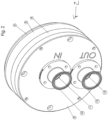
- Fig. 1 shows the pump head 2 of a diaphragm pump 1.
- the diaphragm pump 1 forms part of the Fig. 6 device shown.
- the pump head 2 has a front plate 3, an intermediate plate 4, also referred to as a chamber housing, a valve plate 5 and an end plate 6, also referred to as a membrane carrier, with pump membranes 7, which are connected via pump elements to the Fig. 2 swashplate (not shown).
- a central inlet 10 is provided on the front plate 3, which opens into a central inlet chamber 12 via an inlet channel 11 formed in the front plate 3.
- An outlet 13 is provided on the front plate 3, which is connected to a likewise central outlet chamber 14 of the intermediate plate 4 via an outlet channel 15 formed partly in the front plate 3 and partly in the intermediate plate 4.
- the valve plate 5 is arranged between the intermediate plate 4 and the end plate 6.
- the valve plate 5 has four pump chambers 18 on its rear side 17 facing away from the intermediate plate 4.
- the pump chambers 18, which are open towards the end plate 6, are each closed or delimited by a pump membrane 7.
- the pump membranes 7 are arranged between the end plate 6 and the valve plate 5.
- An annular bead 19 of the pump membrane 7 is arranged in a groove 20 of the valve plate 5 arranged around the pump chamber 18.
- the intermediate plate 4 closes the inlet chamber 12 of the front plate 3, but has inlet channels 16 leading to inlet valves 22, which lead through the outlet chamber 14 of the intermediate plate 4.
- the valve plate 5 has four inlet valves 22, which are designed as umbrella valves and which connect the inlet chamber 12 via the respective channels 16 to the pump chamber 18 assigned to the respective inlet valve 22.
- the valve plate 5 also seals the central outlet chamber 14 of the intermediate plate 4.
- the valve plate 5 is essentially flat and has four outlet valves 24 corresponding to the outlet chamber 14, which are also designed as umbrella valves.
- the outlet opening of the outlet valve 24 is formed by outlet opening sections 23a of the respective outlet valve 24, which surround inlet opening sections 23b of the inlet valve 22 assigned to the same pump chamber 18, which form the inlet opening of the inlet valve 22.
- the outlet opening sections 23a preferably border directly on the inlet opening sections 23b, wherein the respective outlet opening sections 23a and the inlet opening sections 23b are separated from one another in particular by a bead or wall.
- the in Fig. 6 The swash plate 9 shown is connected to a pin 26 of a drive shaft 27 via a ball bearing 25.
- the pin 26 is inclined relative to the longitudinal axis 28 of the drive shaft 27 in order to generate a wobbling movement of the swash plate 8.
- the connection between the drive axis and the swash plate 8 is arranged in the region of a drive chamber 29 in front of the end plate 6.
- the inlet chamber 12 is sealed off from the intermediate plate 4 by a seal 30, which in the example is designed as a cord ring seal.
- the outer boundary of the outlet chamber 14 is sealed off by a seal 31, which in the example is also designed as a cord ring seal.
- the outlet openings 23a of the valve plate 5 are also sealed off from the inlet channels 16 of the intermediate plate 4 by beads 34 arranged in a groove 33 on the umbrella-like valve body of the outlet valve 24.
- the swash plate 8 By rotating the drive shaft 27 about its longitudinal axis 28, the swash plate 8 is set into a circular wobbling motion due to the inclination of the pin 26, without rotating with the drive shaft 27.
- the wobbling motion of the swash plate 8 sets the pump diaphragms 7 into a periodic axial pumping motion, by which negative pressure is generated in the pump chambers 18 alternately in the intake stroke by a movement in the direction of the drive chamber 29 and positive pressure is generated in the exhaust stroke by a movement in the direction of the front plate 3.
- the inlet valve 22 Due to the downstream arrangement of the valve shield of the inlet valve 22, the inlet valve 22 opens and the corresponding outlet valve 24 closes automatically when there is negative pressure in the associated pump chamber 18. If there is excess pressure in the pump chamber 18, the associated inlet valve 22 closes and the corresponding outlet valve 24 opens automatically.
- This Pump medium is pumped out of the pump chamber 18 through the outlet chamber 14 to the outlet 13.
- Fig. 2 shows a perspective front view of the pump head of Fig. 1 with a valve plate.
- the sequence of the components front plate 3, intermediate plate 4, valve plate 5 and end plate 6 can be seen.
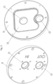
- Fig. 3 shows a front and rear view of the front plate 3 of the pump head according to the invention of Fig. 1
- the inlet channel 11, the outlet channel 15 and the inlet chamber 12 are clearly visible here.
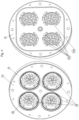
- Fig. 4 shows a front and rear view of a valve plate 5 of the pump head according to the invention of Fig. 1
- the ring-shaped outlet valves 24, the circular segment-like outlet openings 23a and inlet openings 23b in the form of holes in the pump chamber 18 are particularly visible, as are the disc-like inlet valves 22.
Landscapes
- Engineering & Computer Science (AREA)
- Mechanical Engineering (AREA)
- General Engineering & Computer Science (AREA)
- Reciprocating Pumps (AREA)
- Compressor (AREA)
- Details Of Reciprocating Pumps (AREA)
Priority Applications (1)
| Application Number | Priority Date | Filing Date | Title |
|---|---|---|---|
| EP24175473.8A EP4438899A3 (fr) | 2016-11-23 | 2016-11-23 | Pompe à membrane |
Applications Claiming Priority (2)
| Application Number | Priority Date | Filing Date | Title |
|---|---|---|---|
| EP16002479.0A EP3327287B1 (fr) | 2016-11-23 | 2016-11-23 | Pompe à membrane |
| EP24175473.8A EP4438899A3 (fr) | 2016-11-23 | 2016-11-23 | Pompe à membrane |
Related Parent Applications (1)
| Application Number | Title | Priority Date | Filing Date |
|---|---|---|---|
| EP16002479.0A Division EP3327287B1 (fr) | 2016-11-23 | 2016-11-23 | Pompe à membrane |
Publications (2)
| Publication Number | Publication Date |
|---|---|
| EP4438899A2 true EP4438899A2 (fr) | 2024-10-02 |
| EP4438899A3 EP4438899A3 (fr) | 2024-12-04 |
Family
ID=57394311
Family Applications (2)
| Application Number | Title | Priority Date | Filing Date |
|---|---|---|---|
| EP16002479.0A Active EP3327287B1 (fr) | 2016-11-23 | 2016-11-23 | Pompe à membrane |
| EP24175473.8A Pending EP4438899A3 (fr) | 2016-11-23 | 2016-11-23 | Pompe à membrane |
Family Applications Before (1)
| Application Number | Title | Priority Date | Filing Date |
|---|---|---|---|
| EP16002479.0A Active EP3327287B1 (fr) | 2016-11-23 | 2016-11-23 | Pompe à membrane |
Country Status (4)
| Country | Link |
|---|---|
| US (1) | US11085433B2 (fr) |
| EP (2) | EP3327287B1 (fr) |
| JP (3) | JP7446702B2 (fr) |
| ES (1) | ES2987486T3 (fr) |
Families Citing this family (10)
| Publication number | Priority date | Publication date | Assignee | Title |
|---|---|---|---|---|
| WO2018079375A1 (fr) * | 2016-10-27 | 2018-05-03 | 日東工器株式会社 | Pompe à liquides |
| USD923060S1 (en) * | 2018-08-09 | 2021-06-22 | Psg Germany Gmbh | Pump |
| EP3847369B1 (fr) * | 2018-09-06 | 2023-08-30 | Cytiva Sweden AB | Pompe à fluide radial |
| WO2020073249A1 (fr) * | 2018-10-08 | 2020-04-16 | 深圳华星恒泰泵阀有限公司 | Pompe miniature à membrane de mélange air-liquide |
| DE102018008036A1 (de) * | 2018-10-11 | 2020-04-16 | Almatec Maschinenbau Gmbh | Membranpumpe |
| DE102019106370A1 (de) | 2019-03-13 | 2020-09-17 | Psg Germany Gmbh | Ventilanordnungen für eine Membranpumpe, Ventilkörper eines Ventils einer Membranpumpe, Ventilplatte einer Membranpumpe, Membranpumpe, Verfahren zum Betreiben einer Membranpumpe |
| GB201912057D0 (en) | 2019-08-22 | 2019-10-09 | Ge Healthcare Bio Sciences Ab | A diaphragm pump |
| US11933286B1 (en) * | 2021-09-02 | 2024-03-19 | Psg Germany Gmbh | Diaphragm pumping |
| US20240053315A1 (en) * | 2022-08-09 | 2024-02-15 | Triple Win Technology(Shenzhen) Co.Ltd. | Gas sampling mechanism and gas analysis device having the same |
| WO2025254840A1 (fr) * | 2024-06-07 | 2025-12-11 | Wanner Engineering, Inc. | Ensemble de clapets pour une pompe à membrane |
Citations (3)
| Publication number | Priority date | Publication date | Assignee | Title |
|---|---|---|---|---|
| DE10117531A1 (de) | 2001-04-07 | 2002-10-17 | Quattroflow Fluid Systems Gmbh | Membranpumpe |
| DE202006020237U1 (de) | 2006-10-25 | 2008-02-21 | Quattroflow Fluid Systems Gmbh & Co. Kg | Membranpumpe |
| DE102008035592B4 (de) | 2008-07-31 | 2014-10-30 | Almatec Maschinenbau Gmbh | Membranpumpe |
Family Cites Families (15)
| Publication number | Priority date | Publication date | Assignee | Title |
|---|---|---|---|---|
| DE531C (de) * | 1877-08-01 | J Krueger Chemiker | Fixirsalz für Photogramme | |
| CH180763A (de) * | 1934-03-09 | 1935-11-15 | Blaskopf Max | Elektrisch angetriebene Flüssigkeitspumpe. |
| US2213256A (en) * | 1937-01-05 | 1940-09-03 | Sullivan Machinery Co | Fluid compressor |
| US2424595A (en) * | 1944-03-13 | 1947-07-29 | Hydraulic Impact Tool Company | Pumping mechanism |
| US2407792A (en) * | 1945-02-05 | 1946-09-17 | James O Mcmillan | Diaphragm pump |
| US3900276A (en) * | 1973-05-16 | 1975-08-19 | Mcculloch Corp | Diaphragm pump method and apparatus |
| US4721443A (en) * | 1987-03-16 | 1988-01-26 | Tecumseh Products Company | Discharge valve retainer for a compressor |
| DE4118652C2 (de) * | 1991-02-02 | 1996-09-26 | Knf Neuberger Gmbh | Pumpe, vorzugsweise Membranpumpe |
| JPH0663878U (ja) * | 1993-02-10 | 1994-09-09 | 東京特殊電線株式会社 | ダイヤフラムポンプ |
| US7040877B2 (en) * | 2003-02-25 | 2006-05-09 | Copeland Corporation | Compressor valve plate |
| US7364413B2 (en) * | 2003-10-08 | 2008-04-29 | Carrier Corporation | Reciprocating compressor with enlarged valve seat area |
| JP5364447B2 (ja) * | 2009-05-27 | 2013-12-11 | 多田プラスチック工業株式会社 | 流体用ダイヤフラムポンプ |
| EP3093492B1 (fr) * | 2013-10-25 | 2019-09-11 | Xiamen Koge Micro Tech Co., Ltd | Plaque porte-soupapes et pompe à air la comportant |
| EP3146211A4 (fr) * | 2014-05-20 | 2018-02-14 | Ying Lin Cai | Structure de rondelle excentrique pour pompe à diaphragme de compression à effets multiples |
| JP2016006315A (ja) * | 2014-05-30 | 2016-01-14 | アスモ株式会社 | 電動ポンプ |
-
2016
- 2016-11-23 EP EP16002479.0A patent/EP3327287B1/fr active Active
- 2016-11-23 EP EP24175473.8A patent/EP4438899A3/fr active Pending
- 2016-11-23 ES ES16002479T patent/ES2987486T3/es active Active
-
2017
- 2017-11-08 US US15/807,289 patent/US11085433B2/en active Active
- 2017-11-21 JP JP2017223908A patent/JP7446702B2/ja active Active
-
2023
- 2023-11-20 JP JP2023196915A patent/JP7594649B2/ja active Active
-
2024
- 2024-11-22 JP JP2024204177A patent/JP2025024208A/ja active Pending
Patent Citations (3)
| Publication number | Priority date | Publication date | Assignee | Title |
|---|---|---|---|---|
| DE10117531A1 (de) | 2001-04-07 | 2002-10-17 | Quattroflow Fluid Systems Gmbh | Membranpumpe |
| DE202006020237U1 (de) | 2006-10-25 | 2008-02-21 | Quattroflow Fluid Systems Gmbh & Co. Kg | Membranpumpe |
| DE102008035592B4 (de) | 2008-07-31 | 2014-10-30 | Almatec Maschinenbau Gmbh | Membranpumpe |
Also Published As
| Publication number | Publication date |
|---|---|
| EP4438899A3 (fr) | 2024-12-04 |
| JP2025024208A (ja) | 2025-02-19 |
| JP7594649B2 (ja) | 2024-12-04 |
| US11085433B2 (en) | 2021-08-10 |
| JP7446702B2 (ja) | 2024-03-11 |
| JP2018084233A (ja) | 2018-05-31 |
| EP3327287A1 (fr) | 2018-05-30 |
| JP2024023352A (ja) | 2024-02-21 |
| US20180142684A1 (en) | 2018-05-24 |
| EP3327287B1 (fr) | 2024-05-15 |
| EP3327287C0 (fr) | 2024-05-15 |
| ES2987486T3 (es) | 2024-11-15 |
Similar Documents
| Publication | Publication Date | Title |
|---|---|---|
| EP3327287B1 (fr) | Pompe à membrane | |
| DE102008035592B4 (de) | Membranpumpe | |
| EP3864291B1 (fr) | Pompe à membrane | |
| DE3718967C2 (de) | Pumpe | |
| EP0733802B1 (fr) | Pompe à membrane façonnée | |
| DE19607573B4 (de) | Kraftstoffpumpe und Verfahren zu ihrer Herstellung | |
| EP1759137B1 (fr) | Soupape de retenue | |
| DE102007021290A1 (de) | Kolbenpumpe mit abgestuftem Zylinder | |
| EP0550810A2 (fr) | Pompe à membrane double | |
| WO2020182921A9 (fr) | Dispositifs de clapet destinés à une pompe à membrane | |
| DE1907454A1 (de) | Membranpumpe | |
| DE20309616U1 (de) | Wasserstrahleinrichtung zum Trennen einer biologischen Struktur | |
| DE2420175A1 (de) | Elektrisches differentialventil zur fluessigkeitssteuerung | |
| DE69723144T2 (de) | Doppelmembranpumpe | |
| DE1653577B2 (de) | Membranpumpe | |
| DE10210295A1 (de) | Struktur zur Entfernung von Fremdstoffen in einem Fluidkreislauf und ein damit ausgestatteter Kompressor | |
| DE102005022026A1 (de) | Kraftstoffpumpe mit einseitigem Verdichter | |
| DE102015105304A1 (de) | Membranpumpe | |
| DE60204515T2 (de) | Verdichterzylinderkopfdichtung | |
| CH664914A5 (de) | Einrichtung zum verdichten einer masse von koernigem formstoff. | |
| DE102006001568B4 (de) | Kraftstoffpumpe | |
| DE102017117983A1 (de) | Pumpen-Einheit, damit ausgestattete Lagervorrichtung sowie Verfahren zum Betreiben der Lagervorrichtung | |
| DE202013101459U1 (de) | Hochleistungsluftpumpe mit doppelter Lufteinströmung | |
| DE102023120671A1 (de) | Drehventil zur Verwendung bei einem Fluiddosierer | |
| WO2004097220A1 (fr) | Pompe a vide a piston |
Legal Events
| Date | Code | Title | Description |
|---|---|---|---|
| PUAI | Public reference made under article 153(3) epc to a published international application that has entered the european phase |
Free format text: ORIGINAL CODE: 0009012 |
|
| STAA | Information on the status of an ep patent application or granted ep patent |
Free format text: STATUS: THE APPLICATION HAS BEEN PUBLISHED |
|
| STAA | Information on the status of an ep patent application or granted ep patent |
Free format text: STATUS: REQUEST FOR EXAMINATION WAS MADE |
|
| AC | Divisional application: reference to earlier application |
Ref document number: 3327287 Country of ref document: EP Kind code of ref document: P |
|
| AK | Designated contracting states |
Kind code of ref document: A2 Designated state(s): AL AT BE BG CH CY CZ DE DK EE ES FI FR GB GR HR HU IE IS IT LI LT LU LV MC MK MT NL NO PL PT RO RS SE SI SK SM TR |
|
| 17P | Request for examination filed |
Effective date: 20240911 |
|
| RBV | Designated contracting states (corrected) |
Designated state(s): AL AT BE BG CH CY CZ DE DK EE ES FI FR GB GR HR HU IE IS IT LI LT LU LV MC MK MT NL NO PL PT RO RS SE SI SK SM TR |
|
| REG | Reference to a national code |
Ref country code: DE Ref legal event code: R079 Free format text: PREVIOUS MAIN CLASS: F04B0053100000 Ipc: F04B0043000000 |
|
| PUAL | Search report despatched |
Free format text: ORIGINAL CODE: 0009013 |
|
| AK | Designated contracting states |
Kind code of ref document: A3 Designated state(s): AL AT BE BG CH CY CZ DE DK EE ES FI FR GB GR HR HU IE IS IT LI LT LU LV MC MK MT NL NO PL PT RO RS SE SI SK SM TR |
|
| RIC1 | Information provided on ipc code assigned before grant |
Ipc: F04B 53/10 20060101ALI20241030BHEP Ipc: F04B 43/02 20060101ALI20241030BHEP Ipc: F04B 43/00 20060101AFI20241030BHEP |
|
| REG | Reference to a national code |
Ref country code: HK Ref legal event code: DE Ref document number: 40116859 Country of ref document: HK |
|
| STAA | Information on the status of an ep patent application or granted ep patent |
Free format text: STATUS: EXAMINATION IS IN PROGRESS |
|
| 17Q | First examination report despatched |
Effective date: 20260310 |