EP4443009A1 - Gebläse - Google Patents
Gebläse Download PDFInfo
- Publication number
- EP4443009A1 EP4443009A1 EP22900990.7A EP22900990A EP4443009A1 EP 4443009 A1 EP4443009 A1 EP 4443009A1 EP 22900990 A EP22900990 A EP 22900990A EP 4443009 A1 EP4443009 A1 EP 4443009A1
- Authority
- EP
- European Patent Office
- Prior art keywords
- spacing
- sleeve
- cap
- distance
- housing
- Prior art date
- Legal status (The legal status is an assumption and is not a legal conclusion. Google has not performed a legal analysis and makes no representation as to the accuracy of the status listed.)
- Withdrawn
Links
Images





Classifications
-
- F—MECHANICAL ENGINEERING; LIGHTING; HEATING; WEAPONS; BLASTING
- F04—POSITIVE - DISPLACEMENT MACHINES FOR LIQUIDS; PUMPS FOR LIQUIDS OR ELASTIC FLUIDS
- F04D—NON-POSITIVE-DISPLACEMENT PUMPS
- F04D19/00—Axial-flow pumps
- F04D19/002—Axial flow fans
-
- F—MECHANICAL ENGINEERING; LIGHTING; HEATING; WEAPONS; BLASTING
- F04—POSITIVE - DISPLACEMENT MACHINES FOR LIQUIDS; PUMPS FOR LIQUIDS OR ELASTIC FLUIDS
- F04D—NON-POSITIVE-DISPLACEMENT PUMPS
- F04D25/00—Pumping installations or systems
- F04D25/02—Units comprising pumps and their driving means
- F04D25/06—Units comprising pumps and their driving means the pump being electrically driven
- F04D25/0606—Units comprising pumps and their driving means the pump being electrically driven the electric motor being specially adapted for integration in the pump
- F04D25/0613—Units comprising pumps and their driving means the pump being electrically driven the electric motor being specially adapted for integration in the pump the electric motor being of the inside-out type, i.e. the rotor is arranged radially outside a central stator
- F04D25/0626—Details of the lubrication
-
- F—MECHANICAL ENGINEERING; LIGHTING; HEATING; WEAPONS; BLASTING
- F04—POSITIVE - DISPLACEMENT MACHINES FOR LIQUIDS; PUMPS FOR LIQUIDS OR ELASTIC FLUIDS
- F04D—NON-POSITIVE-DISPLACEMENT PUMPS
- F04D29/00—Details, component parts, or accessories
- F04D29/05—Shafts or bearings, or assemblies thereof, specially adapted for elastic fluid pumps
- F04D29/056—Bearings
- F04D29/057—Bearings hydrostatic; hydrodynamic
-
- F—MECHANICAL ENGINEERING; LIGHTING; HEATING; WEAPONS; BLASTING
- F04—POSITIVE - DISPLACEMENT MACHINES FOR LIQUIDS; PUMPS FOR LIQUIDS OR ELASTIC FLUIDS
- F04D—NON-POSITIVE-DISPLACEMENT PUMPS
- F04D29/00—Details, component parts, or accessories
- F04D29/06—Lubrication
- F04D29/063—Lubrication specially adapted for elastic fluid pumps
-
- F—MECHANICAL ENGINEERING; LIGHTING; HEATING; WEAPONS; BLASTING
- F04—POSITIVE - DISPLACEMENT MACHINES FOR LIQUIDS; PUMPS FOR LIQUIDS OR ELASTIC FLUIDS
- F04D—NON-POSITIVE-DISPLACEMENT PUMPS
- F04D29/00—Details, component parts, or accessories
- F04D29/08—Sealings
- F04D29/10—Shaft sealings
Definitions
- the present disclosure relates to blowers.
- the air bubbles may cause the shaft and the sleeve to come into direct contact, which may cause seizing.
- an object of the present disclosure is to provide a blower with less seizing issues.
- a blower includes: a housing including a recess that is open upward; a sleeve disposed in the recess and including a first through-hole; a cap disposed above the sleeve and including a second through-hole; a shaft extending through the first through-hole and the second through-hole; a propeller connected to an upper end of the shaft; and a lubricant, wherein a lower end portion of the cap is housed in the recess, first spacing is formed between an outer side surface of the shaft and an inner side surface of the sleeve, second spacing is formed between an outer side surface of the sleeve and an inner side surface of the housing, third spacing that is connected to the first spacing and the second spacing is formed between a lower surface of the cap and an upper surface of the sleeve, a first distance in the third spacing is less than a second distance in the third spacing, the first distance being a distance between an outer side surface of the cap and the slee
- blower according to one aspect of the present disclosure, seizing issues can be reduced.
- a blower includes: a housing including a recess that is open upward; a sleeve disposed in the recess and including a first through-hole; a cap disposed above the sleeve and including a second through-hole; a shaft extending through the first through-hole and the second through-hole; a propeller connected to an upper end of the shaft; and a lubricant, wherein a lower end portion of the cap is housed in the recess, first spacing is formed between an outer side surface of the shaft and an inner side surface of the sleeve, second spacing is formed between an outer side surface of the sleeve and an inner side surface of the housing, third spacing that is connected to the first spacing and the second spacing is formed between a lower surface of the cap and an upper surface of the sleeve, a first distance in the third spacing is less than a second distance in the third spacing, the first distance being a distance between an outer side surface of the cap and the slee
- the first distance is less than the second distance in the third spacing in which the lubricant is housed and therefore, with this difference in distance, the lubricant smoothly flows from the second distance to the first distance in the third spacing. Since the third spacing is connected to the first spacing and the second spacing, the lubricant flows from the first spacing to the second spacing via the third spacing because of the aforementioned flow in this area. With this flow, air bubbles in the lubricant can be kept from accumulating at a predetermined location, and therefore seizing issues in the shaft and the sleeve due to the air bubbles can be reduced.
- the cap include a third through-hole at a position opposite the third spacing.
- the lubricant in the third spacing is connected to the outside through the third through-hole of the cap. Accordingly, the air bubbles in the lubricant can be released through the third through-hole to the outside of the cap. Therefore, clogging of the third spacing with the air bubbles can be minimized, and it is possible to achieve a stable flow of the lubricant.
- the propeller include: a cover portion configured to cover the third through-hole from above; and a blade extending from the cover portion.
- the cover portion covers the third through-hole, and therefore it is possible to restrict the entry of dust and the like through the third through-hole.
- the outer side surface of the sleeve or the inner side surface of the housing include a cylindrical surface that forms the second spacing.
- the second spacing includes a step or the like in a cross-sectional view along the axis of the shaft, air bubbles may accumulate at the step portion.
- the outer side surface of the sleeve or the inner side surface of the housing includes a cylindrical surface that forms the second spacing, it is possible to reduce steps in the second spacing, and air bubble accumulation can be minimized. This allows the air bubbles to smoothly flow along with the lubricant in the second spacing.
- the outer side surface of the sleeve or the inner side surface of the housing include a groove that forms the second spacing.
- the second spacing includes a groove formed on the outer side surface of the sleeve or a groove formed on the inner side surface of the housing, and therefore a flow path for the lubricant can be formed using these grooves. This flow path allows the lubricant to flow smoothly.
- a lower end portion of the shaft be located at a level below a lower surface of the sleeve, and fourth spacing that is connected to the first spacing and the second spacing be formed between a bottom surface of the recess and the lower surface of the sleeve.
- fourth spacing that is connected to the first spacing and the second spacing is formed between the bottom surface of the recess of the housing and the lower surface of the sleeve, and therefore it is possible to circulate the lubricant through the fourth spacing, the second spacing, and the third spacing in the stated order when starting from the first spacing.
- This circulation makes it easy to release the air bubbles in the lubricant to the outside, allowing a further reduction in seizing issues.
- a third distance between the bottom surface of the recess and the lower surface of the sleeve in the fourth spacing be greater than a fourth distance between the outer side surface of the sleeve and the inner side surface of the housing in the second spacing.
- the third distance in the fourth spacing is greater than the fourth distance in the second spacing, and therefore the lubricant can flow smoothly from the fourth spacing to the second spacing.
- the flow of the lubricant in a circulation path becomes smooth, making it easier to release the air bubbles to the outside.
- the cap project upward from the housing.
- the cap projects upward from the housing, and therefore it is possible to minimize the leakage of the lubricant at this projecting portion. Accordingly, the lubricant can flow stably for a long period of time.
- the outer side surface of the shaft or the inner side surface of the sleeve include a guide groove in which the lubricant is propelled downward during rotation of the shaft.
- the outer side surface of the shaft or the inner side surface of the sleeve includes a guide groove in which the lubricant is propelled downward during rotation of the shaft, and therefore it is possible to force the lubricant from the first spacing to the fourth spacing or from the third spacing to the first spacing. This allows the lubricant to flow more smoothly, making it easy to release the air bubbles to the outside.
- the housing include a fixing portion configured to fix the cap.
- the cap is fixed with the fixing portion of the housing, and therefore the fall of the cap can be minimized, and the leakage of the lubricant can also be minimized. Furthermore, when the cap is fixed, variations in the first distance and the second distance in the third spacing can be reduced. Accordingly, the lubricant can flow stably for a long period of time.
- the sleeve be cylindrical and be fixed to the housing.
- blowers according to exemplary embodiments (including variations thereof) of the present invention will be described.
- each exemplary embodiment described below shows a general or specific example.
- the numerical values, shapes, materials, structural elements, the arrangement and connection of the structural elements, etc., shown in the following exemplary embodiments are mere examples, and are not intended to limit the present invention.
- the respective figures do not necessarily show precise dimensions, etc.,
- the same or similar structural elements are assigned the same reference signs throughout the figures.
- a direction along the axis of a shaft included in the blower is defined as a Z-axis direction, and directions orthogonal to each other in a plane orthogonal to the Z-axis direction are defined as an X-axis direction and a Y-axis direction. Note that depending on the mode of use, it is conceivable that the Z-axis direction may be other than the up-down direction; however, for the sake of explanation, the following description assumes that the Z-axis direction is the up-down direction.
- an expression indicating a relative direction or a posture such as “parallel” and “orthogonal” encompasses a direction or posture that is not the intended direction or posture in a strict sense.
- the sentence “two directions are parallel” not only means that said two directions are perfectly parallel, but also means that said two directions are substantially parallel, specifically, for example, about a few percent difference between said two directions is allowed.
- FIG. 1 is a perspective view illustrating the external appearance of blower 10 according to the exemplary embodiment.
- Fig. 2 is a cross-sectional perspective view of blower 10 according to the exemplary embodiment. Specifically, Fig. 2 is a cross-sectional perspective view in which a cut surface including line II-II in Fig. 1 is viewed.
- blower 10 includes frame 20, rotor portion 30, stator portion 40, and bearing portion 50.
- Frame 20 which is a member that houses rotor portion 30, stator portion 40, and bearing portion 50, includes opening portion 21 in the shape of a column that is open in the up-down direction.
- Opening portion 21 in the shape of a column that is open in the up-down direction.
- a plurality of beam portions 22 (in Fig. 2 , only one beam portion 22 is illustrated) extending from the inner edge to the center of opening portion 21 are arranged radially.
- Base 23 that holds rotor portion 30, stator portion 40, and bearing portion 50 is coupled to leading ends of the plurality of beam portions 22. In other words, base 23 is disposed in a center area of opening portion 21.
- Rotor portion 30 includes propeller 31, yoke 32, and magnet 33.
- Propeller 31 includes: body portion 311 in the shape of a cylinder with a closed bottom; and a plurality of blades 312 extending outward from the periphery of body portion 311.
- Body portion 311 is formed in the shape of a cylinder that includes bottom portion 313 in an upper area and is open in a lower area.
- Yoke 32 in the shape of a cylinder is attached to the inner peripheral surface of body portion 311, and magnet 33 in the shape of a cylinder is attached to the inner peripheral surface of yoke 32.
- Shaft 314 in the shape of a column having an axis extending in the Z-axis direction is fixed in an area of bottom portion 313 that is located at the center in a plan view (as viewed in the Z-axis direction).
- Stator portion 40 is a portion that generates magnetic flux according to a drive current.
- Stator portion 40 includes: stator core 41; a plurality of coils 42 attached to stator core 41; and circuit board 43 for supplying electric power to each coil 42.
- Stator core 41 is, for example, a laminated steel plate formed by axially stacking magnetic steel sheets such as silicon steel sheets.
- Stator core 41 is directly or indirectly connected to base 23.
- Stator core 41 includes a plurality of teeth 411 that project outward, and coils 42 are attached to respective teeth 411. As a result, the plurality of coils 42 are arranged at equal intervals along a circumference centered on stator core 41.
- the plurality of coils 42 which are a collection of wound conducting wires, are electrically connected to circuit board 43 disposed directly below coils 42.
- Each coil 42 is disposed inward of yoke 32 and magnet 33.
- Bearing portion 50 is a portion that rotatably supports shaft 314 of propeller 31.
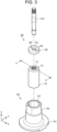
- Fig. 3 is an exploded perspective view of bearing portion 50 and shaft 314 according to the exemplary embodiment. As illustrated in Fig. 3 , bearing portion 50 includes housing 60, sleeve 70, and cap 80.
- Housing 60 is a member that houses a portion of shaft 314, sleeve 70, and cap 80.
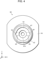
- Fig. 4 is a top view of housing 60 according to the exemplary embodiment. As illustrated in Fig. 3 and Fig. 4 , housing 60 includes: base portion 61 in the form of an oval plate in a plan view; and cylindrical portion 62 projecting upward from base portion 61. Cylindrical portion 62 is open at the top and has a bottom at a lower end. Therefore, the inside of cylindrical portion 62 is recess 63 in the shape of a column including an opening at the top. On the inner peripheral surface of recess 63, a pair of first housing grooves 64 extending from the upper end portion to the bottom along the Z axis is formed at positions that are opposite to each other in the X-axis direction.
- depression 631 in the shape of a circle is formed in a center area of the bottom surface of recess 63, and receiving plate 632 (refer to Fig. 9 ) that receives a leading end of shaft 314 is disposed in depression 631.
- receiving plate 632 (refer to Fig. 9 ) that receives a leading end of shaft 314 is disposed in depression 631.
- a pair of second housing grooves 65 extending along the X axis are formed in order to connect respective first housing grooves 64 and depression 631.
- Fig. 5 is a cross-sectional perspective view of sleeve 70 according to the exemplary embodiment. Specifically, Fig. 5 is a cross-sectional perspective view in which a cut surface including line V-V in Fig. 3 is viewed. As illustrated in Fig. 3 and Fig. 5 , sleeve 70 is a cylindrical member through which first through-hole 71 extending along the Z axis is formed in an area that is located at the center as viewed in the Z-axis direction. In first through-hole 71, shaft 314 is disposed so as to extend through first through-hole 71.
- a plurality of guide grooves 72 are formed on the inner peripheral surface (inner side surface) of sleeve 70, that is, the inner peripheral surface thereof that forms first through-hole 71.
- the plurality of guide grooves 72 are arranged at predetermined intervals in the circumferential direction.
- the shape of each guide groove 72 is such that an upper portion and a lower portion thereof are bent and a middle portion therebetween is in a straight line along the Z-axis. For example, in the case where shaft 314 rotates counterclockwise as viewed in the positive Z-axis direction (as viewed from above), the bent shape of the upper portion and the lower portion of guide groove 72 is tapered in the direction of rotation of shaft 314.
- each guide groove 72 allows lubricant 90 to be propelled downward.
- the number of guide grooves 72 to be provided or the shape of each guide groove 72 are not limited as long as this allows lubricant 90 to be propelled downward.
- the outer peripheral surface (outer side surface) of sleeve 70 which has no constrictions, is a cylindrical surface.
- Projecting portion 73 that projects upward is formed on the upper surface of sleeve 70 around first through-hole 71.
- the outer peripheral surface of projecting portion 73 is tapered upward.
- An area of the upper surface of sleeve 70 other than projecting portion 73 and a leading end surface (upper surface) of projecting portion 73 are flat surfaces.
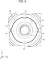
- Fig. 6 is a top view illustrating sleeve 70 according to the exemplary embodiment that is housed in recess 63 of housing 60.
- a plurality of caulked portions 74 are formed in edge areas of the upper surface of sleeve 70. With each caulked portion 74, a portion of the outer peripheral surface of sleeve 70 expands outward and is joined to the inner peripheral surface of housing 60 or fits into first housing groove 64 to the extent that said first housing groove 64 is not blocked, for example.
- sleeve 70 is fixed in recess 63 of housing 60.
- Fig. 7 is a perspective view of cap 80 according to the exemplary embodiment as viewed from above.
- Fig. 8 is a perspective view of cap 80 according to the exemplary embodiment as viewed from below.
- cap 80 is a member formed in the shape of a cylinder, and the inside thereof is second through-hole 81.
- the upper surface of cap 80 is formed flat.
- Cap recess 82 depressed upward in the shape of a truncated cone is formed on the lower surface of cap 80 around second through-hole 81.
- cap grooves 83 extending along the X axis are formed at positions between which second through-hole 81 is located.
- Third through-hole 84 extending up to the upper surface of cap 80 is formed on each cap groove 83 (refer to Fig. 7 and Fig. 9 ).
- Fig. 9 is a cross-sectional view of bearing portion 50 according to the exemplary embodiment.
- Fig. 9 illustrates a cross-section extending along the axis of shaft 314.
- a portion of shaft 314, sleeve 70, and cap 80 are housed in housing 60.
- Shaft 314 is indicated by a dashed-double-dotted line in Fig. 9 .
- receiving plate 632, sleeve 70, and cap 80 in order from a low level are housed in recess 63 of housing 60.
- receiving plate 632 in the shape of a disc is disposed in depression 631 of the bottom surface of recess 63.
- Receiving plate 632 receives a lower end portion of shaft 314 extending through first through-hole 71 of sleeve 70 and second through-hole 81 of cap 80.
- the lower end portion of shaft 314 is located below the lower surface of sleeve 70 and is in contact with receiving plate 632.
- the lower end portion of shaft 314 is formed in the shape of a sphere, and therefore the lower end portion and receiving plate 632 are in contact in the form similar to a point contact. Accordingly, shaft 314 can rotate smoothly.
- Sleeve 70 which is disposed above receiving plate 632, is fixed in recess 63 with caulked portions 74 mentioned above.
- Cap 80 which has a lower end portion housed in recess 63, has an upper end portion projecting from housing 60. Specifically, the lower end portion of cap 80 is fixed by being pressed into recess 63 of housing 60. A portion of housing 60 into which the lower end portion of cap 80 is pressed is fixing portion 67 (refer to Fig. 4 ) that fixes cap 80. Specifically, the lower end portion of cap 80 is pressed and fixed to the upper end portion of recess 63 of housing 60 throughout the entire circumference thereof other than first housing grooves 64; thus, this upper end portion serves as fixing portion 67.
- fixing portion 67 is not limited as long as the fixing portion can fix cap 80.
- a fixing portion using caulk or a fixing portion that fixes cap 80 with another member may also be used.
- a part of the lower end portion of cap 80 that corresponds to each of first housing grooves 64 is at a distance from housing 60, meaning that each of first housing grooves 64 is connected to an external space (refer to circle C in Fig. 9 ).
- First spacing S1 is formed between the outer peripheral surface (outer side surface) of shaft 314 and the inner peripheral surface (inner side surface) of sleeve 70. Specifically, first spacing S1 is provided at paired positions between which shaft 314 is located.
- Second spacing S2 is formed between the outer peripheral surface (outer side surface) of sleeve 70 and the inner peripheral surface (inner side surface) of recess 63 of housing 60. Specifically, second spacing S2 is provided at paired positions between which sleeve 70 is located. Each second spacing S2 includes first housing groove 64 formed on the inner peripheral surface of recess 63. Second spacing S2 has a uniform shape as a whole in a cross-sectional view and extends along the Z axis.
- Third spacing S3 which is connected to first spacing S1 and second spacing S2, is formed between the lower surface of cap 80 and the upper surface of sleeve 70. Specifically, third spacing S3 is provided at paired positions between which shaft 314 is located. Each third spacing S3 includes cap groove 83 formed on the lower surface of cap 80.
- Fourth spacing S4 which is connected to first spacing S1 and second spacing S2, is formed between the lower surface of sleeve 70 and the bottom surface of recess 63 of housing 60. Specifically, fourth spacing S4 is provided at paired positions between which shaft 314 is located. Each fourth spacing S4 includes second housing groove 65 formed on the bottom surface of recess 63.
- Lubricant 90 is housed in recess 63 of housing 60. In Fig. 9 , lubricant 90 is shown with dot shading. Lubricant 90 is also housed in first spacing S1, second spacing S2, third spacing S3, and fourth spacing S4. Lubricant 90 is also housed in second through-hole 81 and each of third through-holes 84 of cap 80.
- Connecting portion 315 which projects downward, is formed in a center area of the lower surface of body portion 311 of propeller 31. Connecting portion 315 is a part to which the upper end portion of shaft 314 fits and is connected. Body portion 311 is disposed above third through-holes 84 and covers third through-holes 84 from above. This means that body portion 311 is one example of a cover portion that covers third through-holes 84 from above.
- blower 10 When an electric current is supplied to each coil 42 of blower 10, magnetic flux is generated at corresponding teeth 411. With the effect of the magnetic flux generated between teeth 411 and magnet 33, torque acting in the circumferential direction is generated between stator portion 40 and rotor portion 30. As a result, propeller 31 rotates around shaft 314, and blades 312 create an air flow. Shaft 314 which rotates is stably supported on bearing portion 50.
- lubricant 90 in recess 63 of housing 60 forms a circulating flow through first spacing S1, fourth spacing S4, second spacing S2, and third spacing S3.
- propulsion attributable to guide grooves 72 of sleeve 70 acts on lubricant 90 in first spacing S1.
- a downward flow of lubricant 90 is produced in first spacing S1.
- Lubricant 90 that has flowed downward in first spacing S1 moves into fourth spacing S4.
- Lubricant 90 flows in second housing groove 65 included in fourth spacing S4, outward in the radial direction of recess 63, and moves into second spacing S2.
- Lubricant 90 flows upward in first housing groove 64 included in second spacing S2, and moves into third spacing S3.
- Lubricant 90 flows in cap groove 83 included in third spacing S3, inward in the radial direction of recess 63, and moves into first spacing S1. When this flow is repeated, lubricant 90 circulates through first spacing S1, fourth spacing S4, second spacing S2, and third spacing S3.
- first spacing S1, second housing groove 65, second housing groove 64, and cap groove 83 form a circulation path.
- lubricant 90 circulates in recess 63 of housing 60, and therefore air bubbles B contained in lubricant 90 can be kept from accumulating in each spacing.
- air bubbles B are released to the outside through third through-holes 84 of cap 80 and first housing grooves 64.
- third through-holes 84 is formed so as to have a cross section that allows the surface tension of lubricant 90 to be maintained.
- first housing grooves 64 is also formed so as to have a cross section that allows the surface tension to be maintained.
- lubricant 90 can easily flow from second distance t2 to first distance t1, allowing smooth circulation as a whole.
- first distance t1 is the distance between the leading end surface of projecting portion 73 of sleeve 70 and the inner top surface of cap recess 82 of cap 80.
- Second distance t2 is the distance between a portion of the upper surface of sleeve 70 other than projecting portion 73 and a portion of the lower surface of cap 80 other than cap recess 82.
- the distance between the inner peripheral surface of projecting portion 73 of sleeve 70 and the inner peripheral surface of cap recess 82 of cap 80 preferably has a value between first distance t1 and second distance t2 in order to achieve smoother circulation.
- third distance t3 between the bottom surface of recess 63 and the lower surface of sleeve 70 in fourth spacing S4 is preferably greater than fourth distance t4 between the outer peripheral surface of sleeve 70 and the inner peripheral surface of recess 63 in second spacing S2 in order to achieve smoother circulation.
- first distance t1 ⁇ second distance t2 ⁇ fourth distance t4 ⁇ third distance t3 is preferably satisfied in order to achieve yet smoother circulation.
- blower 10 includes: housing 60 including recess 63 that is open upward; sleeve 70 disposed in recess 63 and including first through-hole 71; cap 80 disposed above sleeve 70 and including second through-hole 81; shaft 314 extending through first through-hole 71 and second through-hole 81; propeller 31 connected to an upper end of shaft 314; and lubricant 90.
- a lower end portion of cap 80 is housed in recess 63.
- First spacing S1 is formed between an outer peripheral surface (outer side surface) of shaft 314 and an inner peripheral surface (inner side surface) of sleeve 70.
- Second spacing S2 is formed between an outer peripheral surface (outer side surface) of sleeve 70 and an inner peripheral surface (inner side surface) of housing 60.
- Third spacing S3 that is connected to first spacing S1 and second spacing S2 is formed between a lower surface of cap 80 and an upper surface of sleeve 70.
- First distance t1 in third spacing S3 that is a distance between an outer side surface of cap 80 and sleeve 70 or a distance between the outer side surface of sleeve 70 and cap 80 is less than second distance t2 in third spacing S3 that is a distance between an inner side surface of cap 80 and sleeve 70 or a distance between the inner side surface of sleeve 70 and cap 80.
- Lubricant 90 is housed in first spacing S1, second spacing S2, and third spacing S3.
- first distance t1 is less than second distance t2 in third spacing S3 and therefore, the flow in second distance t2 can be fast.
- lubricant 90 can easily flow from second distance t2 to first distance t1, allowing smooth circulation as a whole.
- air bubbles B in lubricant 90 are kept from accumulating at a predetermined location, and therefore seizing issues in shaft 314 and sleeve 70 due to air bubbles B can be reduced.
- cap 80 includes third through-hole 84 at a position opposite third spacing S3.
- lubricant 90 in third spacing S3 is connected to the outside through third through-hole 84 of cap 80. Accordingly, air bubbles B in lubricant 90 can be released through third through-hole 84 to the outside of cap 80. Therefore, clogging of third spacing S3 with air bubbles B can be minimized, and it is possible to achieve stable circulation. Furthermore, since air bubbles B are released to the outside, it is possible to reduce air bubbles B that are drawn into lubricant 90; as a result, seizing issues in shaft 314 and sleeve 70 can be further reduced.
- propeller 31 includes: body portion 311 (cover portion) configured to cover third through-hole 84 from above; and a blade 312 extending from body portion 311.
- body portion 311 covers third through-hole 84, and therefore it is possible to restrict the entry of dust and the like through third through-hole 84.
- outer side surface of sleeve 70 includes a cylindrical surface that forms second spacing S2.
- second spacing S2 includes a step or the like in a cross-sectional view along the axis of shaft 314, air bubbles B may accumulate at the step portion.
- the outer side surface of sleeve 70 includes a cylindrical surface that forms second spacing S2, it is possible to reduce steps in second spacing S2, and accumulation of air bubbles B can be minimized. This allows air bubbles B to smoothly flow along with lubricant 90 in second spacing S2.
- housing 60 includes first housing groove 64 (a groove) that forms second spacing S2.
- second spacing S2 includes first housing groove 64 formed on the inner peripheral surface of housing 60, and therefore a flow path for lubricant 90 can be formed using first housing groove 64. This flow path allows lubricant 90 to flow smoothly.
- a lower end portion of shaft 314 is located at a level below a lower surface of sleeve 70, and fourth spacing S4 that is connected to first spacing S1 and second spacing S2 is formed between a bottom surface of recess 63 and the lower surface of sleeve 70.
- fourth spacing S4 that is connected to first spacing S1 and second spacing S2 is formed between the bottom surface of recess 63 of housing 60 and the lower surface of sleeve 70, and therefore it is possible to circulate lubricant 90 through fourth spacing S4, second spacing S2, and third spacing S3 in the stated order when starting from first spacing S1.
- This circulation makes it easy to release the air bubbles in lubricant 90 to the outside, allowing a further reduction in seizing issues.
- third distance t3 between the bottom surface of recess 63 and the lower surface of sleeve 70 in fourth spacing S4 is greater than fourth distance t4 between the outer peripheral surface of sleeve 70 and the inner peripheral surface of housing 60 in second spacing S2.
- third distance t3 in fourth spacing S4 is greater than fourth distance t4 in second spacing S2, and therefore lubricant 90 can flow smoothly from fourth spacing S4 to second spacing S2.
- the flow of lubricant 90 in a circulation path becomes smooth, making it easier to release air bubbles B to the outside.
- cap 80 projects upward from housing 60.
- cap 80 projects upward from housing 60, and therefore it is possible to minimize the leakage of lubricant 90 at this projecting portion. Accordingly, lubricant 90 can flow stably for a long period of time.
- the inner peripheral surface of sleeve 70 includes guide groove 72 in which lubricant 90 is propelled downward during rotation of shaft 314.
- the inner peripheral surface of sleeve 70 includes guide groove 72 in which lubricant 90 is propelled downward during rotation of shaft 314, and therefore it is possible to force lubricant 90 from first spacing S1 to fourth spacing S4 or from third spacing S3 to first spacing S 1. This allows lubricant 90 to flow more smoothly, making it easy to release air bubbles B to the outside.
- housing 60 includes fixing portion 67 configured to fix cap 80.
- cap 80 is fixed with fixing portion 67 of housing 60, and therefore the fall of cap 80 can be minimized, and the leakage of lubricant 90 can also be minimized. Furthermore, when cap 80 is fixed, variations in first distance t1 and second distance t2 in third spacing S3 can be reduced. Accordingly, lubricant 90 can flow stably for a long period of time.
- sleeve 70 is cylindrical and is fixed to housing 60.
- Blower 10 according to the present exemplary embodiment has been described thus far, but the present invention is not limited to the exemplary embodiment described above.
- the exemplary embodiment disclosed herein is an exemplification in all aspects, and is not intended to be limiting; equivalents of the Claims and all modifications are intended to be included in the scope of the present invention.
- parts that are substantially the same as those in the above exemplary embodiment have the same reference signs as in the above exemplary embodiment, and description thereof may be omitted.
- Fig. 10 is a cross-sectional view of bearing portion 50a according to Variation 1. Specifically, Fig. 10 corresponds to Fig. 9 . As illustrated in Fig. 10 , sleeve 70a included in bearing portion 50a has a lower surface in contact with the bottom surface of housing 60, and there is no fourth spacing (second housing groove). A pair of circulation through-holes 79 which extend through the inner peripheral surface and the outer peripheral surface of sleeve 70a are provided in a lower area of sleeve 70a so as to extend radially. The pair of circulation through-holes 79 are arranged in a straight line and both connected to first spacing S1 and second spacing S2. Each of circulation through-holes 79 constitutes a part of the circulation path for lubricant 90.
- the bearing portion may be without fourth spacing S4 or circulation through-holes 79.
- second distance t2 be set to a value such that capillary action will work.
- capillary action works in second distance t2 and thus, lubricant 90 flows from second distance t2 to first distance t1 in third spacing S3.
- third spacing S3 is connected to first spacing S1 and second spacing S2, the aforementioned flow allows lubricant 90 to flow from first spacing S1 to second spacing S2 via third spacing S3 in this area. With this flow, air bubbles B in lubricant 90 can be kept from accumulating at a predetermined location. Therefore, seizing issues in shaft 314 and sleeve 70 due to air bubbles B can be reduced.
- first housing groove 64 constitutes a part of the circulation path.
- a portion different from first housing groove 64 may constitute a part of the circulation path.
- Fig. 11 is a cross-sectional view of bearing portion 50b according to Variation 2. Specifically, Fig. 11 corresponds to Fig. 9 .
- recess 63b of housing 60b has a shape with no constrictions and the inner peripheral surface thereof is cylindrical. In other words, the first housing groove is not formed in recess 63b.
- a pair of sleeve grooves 75 which extend from the upper end to the lower end of sleeve 70b along the axis thereof are formed on the outer peripheral surface of sleeve 70b.
- Each of sleeve grooves 75 is included in second spacing S2 and constitutes a part of the circulation path. Since the first housing groove is not formed in recess 63b of housing 60b as mentioned earlier, cap 80 is pressed and fixed to the upper end portion of recess 63 throughout the entire circumference thereof. This means that the entire circumference of the upper end portion of recess 63b serves as fixing portion 67b in this case. Note that alternative implementations are possible in which the first housing groove is provided on the inner peripheral surface of the recess of the housing and the sleeve groove is provided on the outer peripheral surface of the sleeve.
- the above exemplary embodiment illustrates the case where the guide groove 72 is formed on the inner peripheral surface of sleeve 70, but a guide groove may be formed on the outer peripheral surface of shaft 314.
- cap 80 formed in the shape of a cylinder, but the cap may include an upper end portion protruding radially outward as a flange portion relative to a lower end portion.
- the flange portion can cover the recess of the housing from above, and therefore leakage of the lubricant can be minimized.
- first distance t1 be set to an appropriate distance selected through experiments, simulations, and the like.
- the above exemplary embodiment illustrates the case where the distance between the inner side surface of cap 80 and sleeve 70 and the distance between the inner side surface of sleeve 70 and cap 80 are the same. However, there are cases where the distance between the inner side surface of cap 80 and sleeve 70 and the distance between the inner side surface of sleeve 70 and cap 80 are different. In this case, it is sufficient that second distance t2 be set to an appropriate distance selected through experiments, simulations, and the like.
- the present disclosure is useful in a blower that is installed in an electronic device, for example.
Landscapes
- Engineering & Computer Science (AREA)
- Mechanical Engineering (AREA)
- General Engineering & Computer Science (AREA)
- Physics & Mathematics (AREA)
- Fluid Mechanics (AREA)
- Structures Of Non-Positive Displacement Pumps (AREA)
- Sliding-Contact Bearings (AREA)
Applications Claiming Priority (2)
| Application Number | Priority Date | Filing Date | Title |
|---|---|---|---|
| JP2021196608A JP7801665B2 (ja) | 2021-12-03 | 2021-12-03 | 送風機 |
| PCT/JP2022/040174 WO2023100557A1 (ja) | 2021-12-03 | 2022-10-27 | 送風機 |
Publications (2)
| Publication Number | Publication Date |
|---|---|
| EP4443009A1 true EP4443009A1 (de) | 2024-10-09 |
| EP4443009A4 EP4443009A4 (de) | 2025-03-05 |
Family
ID=86611949
Family Applications (1)
| Application Number | Title | Priority Date | Filing Date |
|---|---|---|---|
| EP22900990.7A Withdrawn EP4443009A4 (de) | 2021-12-03 | 2022-10-27 | Gebläse |
Country Status (3)
| Country | Link |
|---|---|
| EP (1) | EP4443009A4 (de) |
| JP (1) | JP7801665B2 (de) |
| WO (1) | WO2023100557A1 (de) |
Family Cites Families (9)
| Publication number | Priority date | Publication date | Assignee | Title |
|---|---|---|---|---|
| US6435722B1 (en) * | 2001-01-26 | 2002-08-20 | Sunonwealth Electric Machine Industry Co., Ltd. | Combination structure for oil-impregnated bearing |
| US7455456B2 (en) * | 2003-01-10 | 2008-11-25 | Sony Corporation | Bearing unit and rotation drive device using the same |
| JP2005027431A (ja) * | 2003-07-02 | 2005-01-27 | Nippon Densan Corp | モータ |
| DE10345907B4 (de) | 2003-10-02 | 2007-01-25 | Minebea Co., Ltd. | Hydrodynamisches Lager, Spindelmotor und Festplattenlaufwerk |
| CN100394675C (zh) * | 2004-11-25 | 2008-06-11 | 台达电子工业股份有限公司 | 马达 |
| WO2008139797A1 (ja) | 2007-05-09 | 2008-11-20 | Ntn Corporation | 流体軸受装置 |
| CN101392799B (zh) * | 2007-09-21 | 2010-05-26 | 富准精密工业(深圳)有限公司 | 含油轴承密封结构和采用该含油轴承密封结构的风扇 |
| KR101336584B1 (ko) * | 2012-05-02 | 2013-12-05 | 주식회사 서울금속 | 유체동압베어링 |
| JP2020106045A (ja) | 2018-12-26 | 2020-07-09 | 日本電産株式会社 | 流体動圧軸受装置、モータ、およびファンモータ |
-
2021
- 2021-12-03 JP JP2021196608A patent/JP7801665B2/ja active Active
-
2022
- 2022-10-27 EP EP22900990.7A patent/EP4443009A4/de not_active Withdrawn
- 2022-10-27 WO PCT/JP2022/040174 patent/WO2023100557A1/ja not_active Ceased
Also Published As
| Publication number | Publication date |
|---|---|
| WO2023100557A1 (ja) | 2023-06-08 |
| JP7801665B2 (ja) | 2026-01-19 |
| JP2023082736A (ja) | 2023-06-15 |
| EP4443009A4 (de) | 2025-03-05 |
Similar Documents
| Publication | Publication Date | Title |
|---|---|---|
| CN108933495B (zh) | 马达 | |
| US20090285699A1 (en) | Motor and fan apparatus having the motor | |
| KR20240032119A (ko) | 브러시리스 모터 | |
| JPWO2022118598A5 (de) | ||
| CN109958636B (zh) | 离心风扇 | |
| KR20240031392A (ko) | 브러시리스 모터 | |
| KR20240031395A (ko) | 브러시리스 모터 | |
| KR20240031396A (ko) | 브러시리스 모터 | |
| JP7363287B2 (ja) | モータおよび送風装置 | |
| CN110661351B (zh) | 马达 | |
| EP4443009A1 (de) | Gebläse | |
| CN110661350B (zh) | 马达 | |
| KR20240031393A (ko) | 고정자 코어 | |
| KR20140069949A (ko) | 스위치드 릴럭턴스 모터 어셈블리 및 조립 방법 | |
| CN211018477U (zh) | 马达 | |
| JP2020072543A (ja) | ロータ、ステータ、およびモータ | |
| JP7405089B2 (ja) | モータ | |
| JP6485844B2 (ja) | 回転電機 | |
| CN210444075U (zh) | 风机用定子铁芯及风机 | |
| JP5034070B2 (ja) | ステッピングモータ | |
| WO2024247377A1 (ja) | 送風機 | |
| KR20210123916A (ko) | 모터 | |
| KR102745877B1 (ko) | 로터 및 이를 포함하는 모터 | |
| CN110797998B (zh) | 转子和马达 | |
| KR102323852B1 (ko) | 임펠러 및 이를 구비하는 모터 |
Legal Events
| Date | Code | Title | Description |
|---|---|---|---|
| STAA | Information on the status of an ep patent application or granted ep patent |
Free format text: STATUS: THE INTERNATIONAL PUBLICATION HAS BEEN MADE |
|
| PUAI | Public reference made under article 153(3) epc to a published international application that has entered the european phase |
Free format text: ORIGINAL CODE: 0009012 |
|
| STAA | Information on the status of an ep patent application or granted ep patent |
Free format text: STATUS: REQUEST FOR EXAMINATION WAS MADE |
|
| 17P | Request for examination filed |
Effective date: 20240617 |
|
| AK | Designated contracting states |
Kind code of ref document: A1 Designated state(s): AL AT BE BG CH CY CZ DE DK EE ES FI FR GB GR HR HU IE IS IT LI LT LU LV MC ME MK MT NL NO PL PT RO RS SE SI SK SM TR |
|
| A4 | Supplementary search report drawn up and despatched |
Effective date: 20250131 |
|
| RIC1 | Information provided on ipc code assigned before grant |
Ipc: F04D 29/10 20060101ALI20250127BHEP Ipc: F04D 19/00 20060101ALI20250127BHEP Ipc: F04D 29/063 20060101ALI20250127BHEP Ipc: F04D 25/06 20060101ALI20250127BHEP Ipc: F04D 29/056 20060101AFI20250127BHEP |
|
| DAV | Request for validation of the european patent (deleted) | ||
| DAX | Request for extension of the european patent (deleted) | ||
| STAA | Information on the status of an ep patent application or granted ep patent |
Free format text: STATUS: THE APPLICATION IS DEEMED TO BE WITHDRAWN |
|
| 18D | Application deemed to be withdrawn |
Effective date: 20250819 |