EP4443263A2 - Soupape de régulation de débit et système de recirculation de spa avec pompe à chaleur utilisant la soupape - Google Patents
Soupape de régulation de débit et système de recirculation de spa avec pompe à chaleur utilisant la soupape Download PDFInfo
- Publication number
- EP4443263A2 EP4443263A2 EP23214761.1A EP23214761A EP4443263A2 EP 4443263 A2 EP4443263 A2 EP 4443263A2 EP 23214761 A EP23214761 A EP 23214761A EP 4443263 A2 EP4443263 A2 EP 4443263A2
- Authority
- EP
- European Patent Office
- Prior art keywords
- retainer
- water
- plunger
- heat pump
- pump
- Prior art date
- Legal status (The legal status is an assumption and is not a legal conclusion. Google has not performed a legal analysis and makes no representation as to the accuracy of the status listed.)
- Pending
Links
Images


Classifications
-
- G—PHYSICS
- G05—CONTROLLING; REGULATING
- G05D—SYSTEMS FOR CONTROLLING OR REGULATING NON-ELECTRIC VARIABLES
- G05D7/00—Control of flow
- G05D7/01—Control of flow without auxiliary power
- G05D7/0126—Control of flow without auxiliary power the sensing element being a piston or plunger associated with one or more springs
- G05D7/0133—Control of flow without auxiliary power the sensing element being a piston or plunger associated with one or more springs within the flow-path
Definitions
- Bathing installations such as spas and whirlpool baths typically include water heating systems in recirculating water flow paths to heat the water to desired temperatures.
- the water heaters may utilize electrical power for heating elements submerged in water.
- Heat pumps have also been employed as water heating and cooling systems, to take advantage of the higher efficiency and save power, resulting in lower electrical costs to operate the system.
- Heat pumps typically require an input water flow in a narrow range, e.g. a nominal flow rate plus or minus ten percent or so, for optimal efficiency. Further, the input water flow should be less than a maximum flow rate to ensure the heat pump is not damaged over extended use. These constraints have been difficult to achieve.
- the present invention addresses these constraints.
- FIG. 1 illustrates an exemplary embodiment of a bathing installation 50 employing aspects of the invention.
- the bathing installation is a spa installation, in which a spa tub 10 holds a volume of spa water.
- the spa tub includes one or more inlet ports such as jets, and an outlet port connected to a suction side of water pump 52.
- the spa typically has a series of jets (not shown) fed by a water manifold (not shown).
- a recirculating water flow path 60 formed by pipe segments 60A, 60B ... 60G and 60H delivers heated water to the inlet ports or manifold and draws water from the spa tub.
- the water may be heated by a spa pack 54 including a controller and an electrode heating element, or by heat pump 70, or both, depending on the mode of operation of the spa system, typically under control of the spa pack controller.
- Water exiting the spa pack 54 is delivered through a flow control valve 80 to the heat pump 70.
- a bypass water line 60D may be inserted in the water flow path but how to modulate the bypass flow to meet the several constraints is difficult.
- the water flow path 60 includes pipe segment 60A connected to the output of water pump 52 and to the input of spa pack 54.
- Pipe segment 60B connects the output of the spa pack 54 to pipe T fitting 60I, with the through port connected to flow control valve 80 via pipe section 60C.
- the output of the valve 80 is connected to one end of pipe section 60E, and the other end of the pipe section 60E is connected to the inlet of the heat pump 70.
- Pipe section 60F connects the output of the heat pump 70 to T fitting 60J.
- Pipe section 60G connects the through port of fitting 60G to the inlet port of the spa tub.
- the outlet port of the spa tub is connected by pipe section 60H to the suction side of pump 52.
- the spa pack 54 receives electrical power, typically 230/240 V AC (50-60 Hz).
- the spa pack controls the application of electrical power to the pump 52, the spa pack heater and the heat pump 70.
- a spa control panel 56 is in electrical communication with the spa pack, and includes a display panel for display of spa information and status as well as user input devices such as a touch screen and/or switches to enter user commands.
- a data bus is provided between the spa pack and the heat pump, allowing the spa pack controller to control operation of the heat pump as well as to receive status data from the heat pump.
- the flow control valve 80 functions to regulate water flow into the heat pump to a nominal value plus/minus ten percent, when the pump 52 is a single-speed circulation pump.
- the nominal value is selected to provide optimum efficiency for the heat pump.
- the nominal value is 11.9 gallons per minute (GPM), although this will be dependent on the particular design of the heat pump.
- the flow control valve regulates the water flow to the heat pump to the nominal value plus/minus ten percent. If the water pump is pumping at the high speed, the flow control valve regulates the water flow to the heat pump to be less than a predetermined flow rate which can cause damage to the heat pump.
- That predetermined flow rate is 17.9 GPM.
- the flow control valve must also operate at a flow rate through the spa pack heater of at least a minimum flow rate to avoid damage to the heater. In an exemplary embodiment of the spa pack heater, the minimum flow rate is 23 GPM.
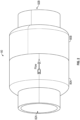
- FIG. 2 is an isometric view of the flow control valve 80.
- Inlet and outlet ports 82A, 82B are configured to connect to pipe segments of the water flow path.
- the ports accept 2-inch diameter pipes.
- the valve includes a housing formed by housing halves 80A, 80B which are glued together.
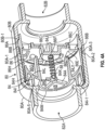
- FIG. 3 is an exploded view of the flow control valve of FIG. 2 .
- the valve There are three internal parts of the valve, which are fitted inside the housing 80A, 80B.
- a plunger structure 84 is configured for sliding movement inside a retainer structure 86 between a fully open position and a closed position.
- An exemplary dimensional tolerance of the gap between the plunger structure and the retainer structure is 0.015 inch +/- .005 inch.
- the housing, plunger structure and retainer structure are fabricated of plastic, such as PVC.
- the plunger structure is biased to the open position by bias structure 88, which in this exemplary embodiment is a spring.
- the plunger structure 84 includes a transverse web structure 84A, defining four openings or orifices 84B, through which water flows when the plunger structure is not in the closed position.
- the size of the orifices is a design parameter.
- the transverse web structure includes a spring retainer post structure 84K extending toward the transverse structure 86C of the retainer structure.
- the retainer structure 86 includes an external peripheral shoulder 86A which seats against the internal peripheral shoulder 80B-1 to register the position of the retainer structure relative to the housing 80B (see FIGS. 4A and 4B ).
- An external peripheral shoulder 86B is contacted by surface 80A-3 of the housing half 80A when the housing halves are assembled together, securing the position of the retainer structure 86 within the assembled housing halves 80A, 80B.
- the retainer structure 86 further includes a transverse structural portion 86C ( FIG. 4A ), extending across the interior cavity 86G of the retainer structure.
- the transverse structural portion has a protruding center boss portion 86D with a spring retainer post 86F extending toward the input opening 82A.
- the transverse structural portion also has a plurality of peripheral openings 86E through the structure and outside of the center boss portion, which openings permit water flow through the transverse structural portion when the plunger portion 84 is not in the closed position.
- the spring 88 is held in position by fitment onto the spring retainer posts 84K and 86F ( FIG. 4A ).
- Embodiments of the plunger structure 84 are illustrated in FIGS. 4A-5D .
- the embodiment of FIGS. 4A and 5A has an outer peripheral cylindrical surface 84H which has an outer diameter sized to fit within the cylindrical surface 86H of the retainer structure 86, with a tolerance designed to allow sliding movement of the plunger structure within the retainer structure, yet without allowing significant water flow in the small gap between the surfaces 84H and 86H.
- An exemplary tolerance dimension is 0.015 inch.
- the plunger structure 84 further includes an interior cylindrical surface 84I inboard of surface 84H, and extending from concave surface portion 84L ( FIG. 4A ).
- the tip 841-1 of surface 84I protrudes further than the tip of the outer cylindrical surface 84H, and serves as a stop surface against surface 80A-5 of the housing half 80A, defining the open position of the valve.
- the plunger structure 84 further includes an interior cylindrical surface 84J extending downwardly from concave surface portion 84L.
- Surface 84J has a draft for molding purposes, but is a true cylinder otherwise.
- the distal edge 84J1 of the interior cylindrical surface 84J serves as a stop surface against the solid surface 86C1 of the transverse structure 86C surrounding the boss 86D. With the plunger structure moved toward the outlet port 82A, the distal edge 84J1 will stop against the solid surface 86C1, cutting off flow through the apertures 86E in the transverse structure 86C. This position of the plunger 84 is the off position.
- FIG. 4B illustrates another embodiment of the valve 80', which is identical to valve 80 illustrated in FIG. 4A , except that the plunger 84' has smaller orifices 84B' than the orifices 84B of valve 80.
- the valve 80' of FIG. 4B will allow lower water flow through the valve than valve 80.
- the size of the orifices is a design parameter, for matching the valve to the water pump capacity, for example.
- the size of the bypass pipe 60D ( FIG. 1 ) is also another design parameter.
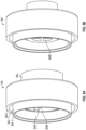
- FIGS. 5A and 5B are side isometric views of the respective plungers 84 and 84'.
- FIGS. 5C and 5D are end views of the respective plungers 84A and 84A', showing the four orifices 84B, 84B' in the respective plungers.
- FIGS. 6A, 6B and 6C illustrate the operation of the exemplary flow control valve 80. As the water pressure increases, the plunger 84 will move toward the retainer 86 and control the amount of water that can flow through the valve.
- FIG. 6A illustrates the plunger 84 in the fully open position relative to the retainer 86, allowing water flow through the orifice in the plunger, around the boss 86D and through the retainer orifices 86E.
- the open position occurs when the water flow through the valve 80 is insufficient to overcome the spring bias to compress the spring.
- FIG. 6B shows the plunger 84 in an intermediate position relative to the retainer 86, with the distal edge 84J1 of the plunger positioned at the tip 86D1 of the boss 86D, reducing the opening size through which water can flow.
- the water flow rate is increased sufficiently to exert sufficient force to compress the spring 88 to the extent illustrated.
- FIG. 6C illustrates the valve 80 with the plunger 84 in the fully closed position, with the spring 88 compressed such that the distal edge 84J1 is positioned against the surface 86C1 of the retainer, effectively closing off the water flow path through the plunger and retainer orifices.
- the flow control valve 80 is an effective tool to allow easy installation of the heat pump 70 in a bathing installation using either a circulation pump or a two-speed pump.
- the valve ensures proper flow through the heat pump and alleviates the need for measuring and optimizing flow when installing the heat pump.
- an exemplary flow control valve 80 using a retainer 84 with the larger orifice size can work in a spa system as illustrated in FIG. 1 with a two-speed pump when using 2-inch pipe plumbing, and with a circulation pump when using 1.5 inch pipe plumbing.
- the high speed operates on a current draw from 8.8 A to 16.4 A, and the low speed on a current draw from 2 A to 4.4 A.
- the circulation pump operates on a current draw of 1A to 1.1A.
- an exemplary flow control valve 80' using a retainer 84' with the smaller orifice size can work in a spa system as illustrated in FIG. 1 with a two-speed pump when using 2-inch pipe plumbing, and with a circulation pump when using 2-inch pipe plumbing.
- the high speed operates on a current draw from 8.8 A to 16.4 A
- the low speed on a current draw from 1 A to 1.1 A
- the circulation pump operates on a current draw of 1A to 1.1A.
Landscapes
- Physics & Mathematics (AREA)
- General Physics & Mathematics (AREA)
- Engineering & Computer Science (AREA)
- Automation & Control Theory (AREA)
- Details Of Reciprocating Pumps (AREA)
- Structures Of Non-Positive Displacement Pumps (AREA)
Applications Claiming Priority (2)
| Application Number | Priority Date | Filing Date | Title |
|---|---|---|---|
| US202263434049P | 2022-12-20 | 2022-12-20 | |
| US18/104,676 US12222736B2 (en) | 2022-12-20 | 2023-02-01 | Flow control valve and spa recirculation system with heat pump using the valve |
Publications (2)
| Publication Number | Publication Date |
|---|---|
| EP4443263A2 true EP4443263A2 (fr) | 2024-10-09 |
| EP4443263A3 EP4443263A3 (fr) | 2024-12-25 |
Family
ID=89121704
Family Applications (1)
| Application Number | Title | Priority Date | Filing Date |
|---|---|---|---|
| EP23214761.1A Pending EP4443263A3 (fr) | 2022-12-20 | 2023-12-06 | Soupape de régulation de débit et système de recirculation de spa avec pompe à chaleur utilisant la soupape |
Country Status (1)
| Country | Link |
|---|---|
| EP (1) | EP4443263A3 (fr) |
Family Cites Families (9)
| Publication number | Priority date | Publication date | Assignee | Title |
|---|---|---|---|---|
| US3319648A (en) * | 1965-04-27 | 1967-05-16 | Deltrol Corp | Pressure-compensated flow control valves |
| US3424196A (en) * | 1966-06-01 | 1969-01-28 | Deltrol Corp | Flow regulating valve |
| US3805824A (en) * | 1972-09-25 | 1974-04-23 | Us Navy | Pressure-compensated flow control valve |
| JP3588948B2 (ja) * | 1996-12-19 | 2004-11-17 | 松下電器産業株式会社 | ヒートポンプ式風呂給湯システム |
| JP2006002960A (ja) * | 2004-06-15 | 2006-01-05 | Matsushita Electric Ind Co Ltd | ヒートポンプ装置 |
| JP2010133593A (ja) * | 2008-12-03 | 2010-06-17 | Sanden Corp | 貯湯式給湯装置 |
| WO2015196198A1 (fr) * | 2014-06-20 | 2015-12-23 | Pentair Water Pool And Spa, Inc. | Appareil de chauffage hybride |
| WO2017212613A1 (fr) * | 2016-06-09 | 2017-12-14 | 三菱電機株式会社 | Unité extérieure d'alimentation en eau chaude à pompe à chaleur |
| JP6645593B2 (ja) * | 2017-01-31 | 2020-02-14 | 三菱電機株式会社 | 熱媒体循環システム |
-
2023
- 2023-12-06 EP EP23214761.1A patent/EP4443263A3/fr active Pending
Also Published As
| Publication number | Publication date |
|---|---|
| EP4443263A3 (fr) | 2024-12-25 |
Similar Documents
| Publication | Publication Date | Title |
|---|---|---|
| EP1835209A2 (fr) | Vanne à triple fonction | |
| US5509463A (en) | Saddle type heat exchanger | |
| CN100366920C (zh) | 阀装置和液压驱动装置 | |
| US11573580B2 (en) | Systems and methods for turning over fluid distribution systems | |
| EP4443263A2 (fr) | Soupape de régulation de débit et système de recirculation de spa avec pompe à chaleur utilisant la soupape | |
| US12312786B2 (en) | Sensing faucet assembly | |
| EP1165964A2 (fr) | Clapet de repartition de charge et systeme permettant de faire fonctionner en parallele des pompes centrifuges | |
| US12222736B2 (en) | Flow control valve and spa recirculation system with heat pump using the valve | |
| JPH11287337A (ja) | 混合比例弁 | |
| CN204467550U (zh) | 一种冷暖床垫 | |
| CN218000512U (zh) | 一种具有回水和流量调节功能的水阀和供水系统 | |
| KR102216548B1 (ko) | 체크밸브 | |
| CN221084909U (zh) | 一种过滤系统、水冷系统以及风力发电机组 | |
| EP4286669A1 (fr) | Dispositif de réapprovisionnement et de drainage de liquide pour système de stockage d'énergie refroidi par liquide et système de stockage d'énergie refroidi par liquide | |
| CN212131391U (zh) | 一种调节阀芯 | |
| JPS6127444A (ja) | 即湯化装置 | |
| JP4325529B2 (ja) | 貯湯式給湯機 | |
| KR19990040999U (ko) | 자동수전의 온/냉수 혼합조절장치 및이를 이용한 급수제어시스템 | |
| CN219511033U (zh) | 一种集成式开水机加热模块 | |
| CN217762147U (zh) | 智能式陶瓷阀 | |
| CN218440810U (zh) | 带自动补水阀的零冷水阀 | |
| CN222316029U (zh) | 一种零冷水循环的阀 | |
| CN221003243U (zh) | 轴封水系统 | |
| CN213119292U (zh) | 一种供暖设备及具有其的供暖系统 | |
| CN115807862B (zh) | 一种三通止回阀、使用方法及污水提升设备 |
Legal Events
| Date | Code | Title | Description |
|---|---|---|---|
| PUAI | Public reference made under article 153(3) epc to a published international application that has entered the european phase |
Free format text: ORIGINAL CODE: 0009012 |
|
| STAA | Information on the status of an ep patent application or granted ep patent |
Free format text: STATUS: THE APPLICATION HAS BEEN PUBLISHED |
|
| AK | Designated contracting states |
Kind code of ref document: A2 Designated state(s): AL AT BE BG CH CY CZ DE DK EE ES FI FR GB GR HR HU IE IS IT LI LT LU LV MC ME MK MT NL NO PL PT RO RS SE SI SK SM TR |
|
| PUAL | Search report despatched |
Free format text: ORIGINAL CODE: 0009013 |
|
| AK | Designated contracting states |
Kind code of ref document: A3 Designated state(s): AL AT BE BG CH CY CZ DE DK EE ES FI FR GB GR HR HU IE IS IT LI LT LU LV MC ME MK MT NL NO PL PT RO RS SE SI SK SM TR |
|
| RIC1 | Information provided on ipc code assigned before grant |
Ipc: G05D 7/01 20060101AFI20241115BHEP |
|
| STAA | Information on the status of an ep patent application or granted ep patent |
Free format text: STATUS: REQUEST FOR EXAMINATION WAS MADE |
|
| 17P | Request for examination filed |
Effective date: 20250513 |
|
| STAA | Information on the status of an ep patent application or granted ep patent |
Free format text: STATUS: EXAMINATION IS IN PROGRESS |
|
| 17Q | First examination report despatched |
Effective date: 20250807 |
|
| GRAP | Despatch of communication of intention to grant a patent |
Free format text: ORIGINAL CODE: EPIDOSNIGR1 |
|
| STAA | Information on the status of an ep patent application or granted ep patent |
Free format text: STATUS: GRANT OF PATENT IS INTENDED |
|
| INTG | Intention to grant announced |
Effective date: 20260212 |