EP1835209A2 - Vanne à triple fonction - Google Patents
Vanne à triple fonction Download PDFInfo
- Publication number
- EP1835209A2 EP1835209A2 EP20070103943 EP07103943A EP1835209A2 EP 1835209 A2 EP1835209 A2 EP 1835209A2 EP 20070103943 EP20070103943 EP 20070103943 EP 07103943 A EP07103943 A EP 07103943A EP 1835209 A2 EP1835209 A2 EP 1835209A2
- Authority
- EP
- European Patent Office
- Prior art keywords
- valve
- flow passage
- valve assembly
- venturi
- flow
- Prior art date
- Legal status (The legal status is an assumption and is not a legal conclusion. Google has not performed a legal analysis and makes no representation as to the accuracy of the status listed.)
- Granted
Links
Images


Classifications
-
- F—MECHANICAL ENGINEERING; LIGHTING; HEATING; WEAPONS; BLASTING
- F16—ENGINEERING ELEMENTS AND UNITS; GENERAL MEASURES FOR PRODUCING AND MAINTAINING EFFECTIVE FUNCTIONING OF MACHINES OR INSTALLATIONS; THERMAL INSULATION IN GENERAL
- F16K—VALVES; TAPS; COCKS; ACTUATING-FLOATS; DEVICES FOR VENTING OR AERATING
- F16K5/00—Plug valves; Taps or cocks comprising only cut-off apparatus having at least one of the sealing faces shaped as a more or less complete surface of a solid of revolution, the opening and closing movement being predominantly rotary
- F16K5/06—Plug valves; Taps or cocks comprising only cut-off apparatus having at least one of the sealing faces shaped as a more or less complete surface of a solid of revolution, the opening and closing movement being predominantly rotary with plugs having spherical surfaces; Packings therefor
- F16K5/0605—Plug valves; Taps or cocks comprising only cut-off apparatus having at least one of the sealing faces shaped as a more or less complete surface of a solid of revolution, the opening and closing movement being predominantly rotary with plugs having spherical surfaces; Packings therefor with particular plug arrangements, e.g. particular shape or built-in means
-
- F—MECHANICAL ENGINEERING; LIGHTING; HEATING; WEAPONS; BLASTING
- F16—ENGINEERING ELEMENTS AND UNITS; GENERAL MEASURES FOR PRODUCING AND MAINTAINING EFFECTIVE FUNCTIONING OF MACHINES OR INSTALLATIONS; THERMAL INSULATION IN GENERAL
- F16K—VALVES; TAPS; COCKS; ACTUATING-FLOATS; DEVICES FOR VENTING OR AERATING
- F16K27/00—Construction of housing; Use of materials therefor
- F16K27/06—Construction of housing; Use of materials therefor of taps or cocks
-
- F—MECHANICAL ENGINEERING; LIGHTING; HEATING; WEAPONS; BLASTING
- F24—HEATING; RANGES; VENTILATING
- F24D—DOMESTIC- OR SPACE-HEATING SYSTEMS, e.g. CENTRAL HEATING SYSTEMS; DOMESTIC HOT-WATER SUPPLY SYSTEMS; ELEMENTS OR COMPONENTS THEREFOR
- F24D19/00—Details
- F24D19/10—Arrangement or mounting of control or safety devices
- F24D19/1006—Arrangement or mounting of control or safety devices for water heating systems
- F24D19/1009—Arrangement or mounting of control or safety devices for water heating systems for central heating
- F24D19/1015—Arrangement or mounting of control or safety devices for water heating systems for central heating using a valve or valves
-
- Y—GENERAL TAGGING OF NEW TECHNOLOGICAL DEVELOPMENTS; GENERAL TAGGING OF CROSS-SECTIONAL TECHNOLOGIES SPANNING OVER SEVERAL SECTIONS OF THE IPC; TECHNICAL SUBJECTS COVERED BY FORMER USPC CROSS-REFERENCE ART COLLECTIONS [XRACs] AND DIGESTS
- Y10—TECHNICAL SUBJECTS COVERED BY FORMER USPC
- Y10T—TECHNICAL SUBJECTS COVERED BY FORMER US CLASSIFICATION
- Y10T137/00—Fluid handling
- Y10T137/8593—Systems
- Y10T137/85978—With pump
-
- Y—GENERAL TAGGING OF NEW TECHNOLOGICAL DEVELOPMENTS; GENERAL TAGGING OF CROSS-SECTIONAL TECHNOLOGIES SPANNING OVER SEVERAL SECTIONS OF THE IPC; TECHNICAL SUBJECTS COVERED BY FORMER USPC CROSS-REFERENCE ART COLLECTIONS [XRACs] AND DIGESTS
- Y10—TECHNICAL SUBJECTS COVERED BY FORMER USPC
- Y10T—TECHNICAL SUBJECTS COVERED BY FORMER US CLASSIFICATION
- Y10T137/00—Fluid handling
- Y10T137/8593—Systems
- Y10T137/87917—Flow path with serial valves and/or closures
- Y10T137/88054—Direct response normally closed valve limits direction of flow
Definitions
- Balancing and flow measurement can be accomplished in several ways by using a calibrated ball valve, venturi, flow meter, or other similar device.
- a balanced system provides better heat and results in energy savings.
- a properly installed heating system also includes flow control, or check, valves to prevent gravity flow. Without flow control valves, uncontrollable heating of zones in a building can occur. With flow control valves, when the circulating pump is off, the flow control valves are closed, preventing unwanted hot water from flowing backward. When the pump turns on, the pressure developed by the pump unseats each flow control valve and allows water to flow past the valve. Additionally, the flow control valves prevent gravity flow and prevent the system fluid from flowing in the wrong or unwanted direction, which can damage the pump and other equipment in the system.
- valve that provides flow control to prevent unwanted backflow, and includes a flow meter and throttling/isolation valve to accurately balance flow through the valve and to shut off flow through the system.
- the present invention provides a valve assembly comprising a valve body having an inlet opening, an outlet opening, and a flow passage extending therebetween.
- a check valve is disposed within the flow passage.
- a shutoff valve is disposed within the flow passage.
- a venturi is disposed within the flow passage between the check valve and the shutoff valve.
- valve assembly comprising a valve body having an inlet opening, an outlet opening, and a flow passage extending therebetween.
- a valve is carried by the valve body. The valve is located in the flow passage to allow or prevent fluid flow through the fluid passage.
- a venturi is formed in the flow passage. A plurality of ports communicate with the venturi.
- the present invention provides a valve assembly comprising a first portion having a first flow passage extending therethrough and a second portion having a second flow passage extending therethrough.
- a check valve is disposed in the first flow passage.
- a venturi is disposed in the first flow passage,
- a shutoff valve is disposed in the second flow passage.
- the present invention provides a fluid system comprising a pump having a suction end and a discharge end and a piping system having a first end connected to the discharge end of the pump and a second end connected to the suction end of the pump.
- a valve assembly is inserted in the piping system between the first end and the second end.
- the valve assembly comprises a valve body having an inlet opening, an outlet opening, and a flow passage extending therebetween.
- a check valve is disposed within the flow passage.
- a shutoff valve is disposed within the flow passage.
- a venturi is disposed within the flow passage between the check valve and the shutoff valve.
- upstream is defined to mean a direction toward the beginning of fluid flow and "downstream” is defined to mean a direction toward the end of fluid flow.
- downstream is defined to mean a direction toward the end of fluid flow.
- Heating systems in buildings must be properly adjusted to achieve balanced heating levels throughout the building. Without a balanced heating system, a room or a portion of the building that is located proximate to the heating source is likely to be warmer than a room or a portion of the building that is farther from the heating source. In order to heat the farther portion of the building to a satisfactory temperature, it may be necessary to overheat the portion of the building that is closer to the heating source, resulting in wasted heat and potential discomfort.
- the triple duty valve assembly 100 includes a device for measuring fluid flow rates, as well as other thermodynamic parameters.
- the measurement capabilities enable an operator to throttle fluid flow, providing for a more energy efficient system in which the valve assembly 100 is installed.
- the valve assembly 100 includes a check valve 120, a venturi 140, and a shutoff valve 160 in the form of a ball valve, all contained therein.
- the valve assembly 100 may be used in heating systems to regulate the flow of hot water through the system in order to optimize the heating system and reduce the cost of operating the heating system.
- the check valve 120 prevents gravity flow and flow in the wrong direction; the venturi 140 is used as a flow measurement device to provide measurement data for accurate flow balancing; and the ball valve 160 throttles and isolates the fluid system in which the valve assembly 100 is inserted.
- the valve assembly 100 includes a body 101 having an inlet opening 102, an outlet opening 104, and a fluid flow passage 106 extending between the openings.
- the check valve 120 is located at the inlet opening 102 and is operative to allow fluid flow from the inlet opening 102 toward the outlet opening 104, and to restrict flow from the outlet opening 104 toward the inlet opening 102.
- the check valve 120 may be located at the outlet opening 104 instead. In such a configuration, the check valve 120 still allows fluid flow from the inlet opening 102 toward the outlet opening 104, and restricts flow from the outlet opening 104 toward the inlet opening 102.
- the check valve 120 is preferably a spring loaded valve that is closed in a no-pressure environment.
- One suitable check valve is disclosed in U.S. Patent Application Publication No. 2004/0226617, published on November 18, 2004 .
- other known check valves may be incorporated into the valve assembly 100 instead.
- the pressure when fluid pressure is applied from the upstream opening 102, the pressure overcomes the force of the spring and opens the check valve 120, allowing fluid flow through the check valve 120.
- the pressure aids the spring in keeping the check valve 120 closed, restricting fluid flow through the check valve 120.
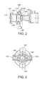
- the check valve 120 is preferably retained within the fluid flow passage 106 by a lip 112 located between the check valve 120 (not shown in Fig. 2) and the venturi 140.
- the lip 112 reduces the diameter of the fluid flow passage 106 and prevents the check valve 120 from moving in a downstream direction toward the venturi 140.
- a groove 114 formed in the body 101 on the upstream side of the check valve 120 accepts a retaining ring 116 (shown in Fig. 1) that prevents the check valve 120 from moving in an upstream direction toward the inlet opening 102.
- the venturi 140 includes an inlet 142 that necks down to a minimal diameter throat 144 and then expands to an outlet 146 that is approximately as wide as the inlet 142. Venturi designs are well known in the art and need not be described in detail.
- the venturi 140 also includes a pair of internally threaded ports 148, 150 that tap off the fluid flow passage 106 upstream of the inlet 142. The ports 148, 150 are spaced 180 degrees around the fluid flow passage 106 from each other.
- the port 148 extends from a top portion of the valve assembly 100 and the port 150 extends from a bottom portion of the valve assembly 100.
- the ports 148, 150 may be used to attach, among other things, a vent valve and a drain valve, respectively, as well as pressure gauges, temperature gauges, or other hydronic accessories.
- an additional pair of threaded ports 152, 154 tap off the venturi 140 at the throat 144.
- the ports 152, 154 are spaced 180 degrees around the fluid flow passage 106 from each other, and are preferably orthogonal to the ports 148, 150.
- the ports 152, 154 may be used to attach, among other things, pressure gauges, temperature gauges, or other hydronic accessories.
- a first pressure gauge (not shown) is connected to one of the ports 148, 150 and a second pressure gauge (not shown) is connected to one of the ports 152, 154.
- a differential pressure gauge 158 shown in Fig. 2, may be connected to both of the one of the ports 148, 150 and the one of the ports 152, 154.
- the measurement of the pressure difference is used in conjunction with other known or measurable parameters, such as fluid viscosity and venturi size, to determine fluid flow through the valve assembly 100.
- each port 148, 150, 152, 154 Prior to installation of the valve assembly 100 into a fluid system, each port 148, 150, 152, 154 is preferably plugged by a plug 156 (shown in Fig. 1) to prevent debris from entering the ports 148, 150, 152, 154.
- a plug 156 shown in Fig. 1
- the plugs 156 are removed and instrumentation and/or shutoff valves as described above are installed in place of the removed plugs 156.
- the venturi 140 is located downstream of the check valve 120 to minimize restriction at the venturi 140.
- the venturi 140 may be located upstream of the check valve 120, without departing from the spirit and scope of the present invention.
- the shutoff valve 160 is preferably a standard ball valve that is operable over a range of approximately ninety degrees of rotation. The structure and operation of a ball valve is well known to those skilled in the art and need not be described in detail.
- the shutoff valve 160 assists in the balancing process and provides a means to isolate the system, such as for maintenance or repair.
- the shutoff valve 160 is also throttable between a fully open position and a fully closed position.
- the inlet opening 102 includes a union connection fitting 108 for coupling the valve assembly 100 to a tailpiece 170.
- the tailpiece 170 may comprise any of a female sweat connection 172, a male NPT connection 174, or a female NPT connection 176.
- an 0-ring 178 is used to seal the connection between the tailpiece 170 and the body 101.
- a groove 179 is formed in the body 101 to seat the 0-ring 178.
- the outlet opening 104 includes a fixed connection fitting 180.
- the connection fitting 180 may be a female NPT connector 182 or a female sweat connector 184. While the connections shown are preferred connections, those skilled in the art will recognize that other connections may be used.
- the other connections may be fixed connections on both ends; union connections (with tail pieces) on both ends; union end/fixed end; flanged connection on both ends; flanged end/union end; flanged end/fixed end; grooved connection on both ends; grooved connection/fixed end; grooved connection/flanged end; and grooved connection/union end.
- the flanged ends may include a rotatable flange disclosed in either or both of U.S. Patent Application Publication No. 2004/0129913, published on July 8, 2004 or U.S. Patent Application Publication No. 2004/0226617, published on November 18, 2004 .
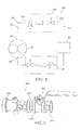
- the valve assembly 100 is preferably used in a fluid system 60 as shown in Fig. 4.
- the fluid system 60 includes a pump 62 having a discharge end 64 and a suction end 66.
- a piping system 68 is connected to the discharge end 62 of the pump 60 such that the piping system 68 fluidly communicates with the pump 60.
- Th valve assembly 100 is fixedly connected to the piping system 68, downstream from the pump 62.
- the upstream opening 102 is connected to an upstream end 72 of the piping system 68 and the downstream opening 104 is connected to a downstream end 74 of the piping system 68.
- An operative device 80 such as a water heater, a radiator, or some other suitable device, is also fixedly connected to the piping system 68, downstream from the pump 60.
- operative device 80 is also shown in Fig. 4 as being located downstream of the valve assembly 100, those skilled in the art will recognize that the operative device 80 may be located upstream of the valve assembly 100. Additionally, a second valve assembly 100' may be located downstream of the operative device 80. The second valve assembly 100' allows the operative device 80 to be isolated from the rest of the fluid system 60 in order to service or remove the operative device 80. Additionally, although not shown, more than one operative device 80 may be installed in the fluid system 60. The piping system 68 extends downstream of the operative device 80 back to the suction end 66 of the pump 62 to form a closed loop. Further, although not shown, the fluid system 60 may include tees and branches with other valve assemblies and operative devices installed therein.
- the valve assembly 100 may be installed in the piping system 68 during initial construction of the fluid system 60, or alternatively, the valve assembly 100 may be backfit into a previously constructed piping system 68 by cutting into the piping system 68 and installing the valve assembly 100.
- Differential pressure gauges may be connected to one of the ports 148, 150 and one of the ports 152, 154 to measure flow rate through the valve assembly 100.
- Such flow measurements provide an operator with sufficient information to determine whether the impeller on the pump that is pumping the fluid through the heating system needs to be reduced in size.
- the reduction in the impeller size not only reduces fluid flow through the system, but also requires less energy to pump the fluid, resulting in lower operational costs.
- the shutoff valve 160 may be throttled down to reduce fluid flow, such action does not take advantage of the financial benefits that may be achieved by reducing the impeller size instead.
- the ability to keep the shutoff valve 160 more fully open, while reducing impeller size provides a financial benefit of the present invention through its lifespan of the system in which the valve assembly 100 is installed.
- FIG. 5 A second embodiment of a valve assembly 200 according to the present invention is shown in Figs. 5 and 6.
- the valve assembly 200 includes an upstream portion 202 and a downstream portion 204.
- the upstream portion 202 includes a check valve (not shown), similar to the check valve 120 described above with respect to the valve assembly 100, and a venturi 240.
- the check valve is insertable into a fluid flow passage 206 in the upstream portion 202.
- the venturi 240 is disposed downstream of the check valve, although those skilled in the art will recognize that the venturi 240 may be installed upstream of the check valve.
- the downstream portion 204 includes a shutoff valve 260 similar to the shutoff valve 160 described above with respect to the valve assembly 100.
- the upstream portion 202 includes a male downstream end 206 that is insertable into a female upstream end 208 of the downstream portion 204 and brazed together to form a solid, liquid tight connection.
- the downstream end 206 and the upstream end 208 may alternatively both include threaded (i.e. NPT) connections for releasable connection of the upstream portion 202 with the downstream portion 204.
- the downstream end 206 and the upstream end 208 may both include smooth walls for a straight insertion fit, and then brazed or soldered together to form a solid connection.
- downstream end 206 and the upstream end 208 may be connected to each other with union fittings, flanged fittings, or grooved fittings.
- the flanged fittings may include a rotatable flange disclosed in either or both of U.S. Patent Application Publication No. 2004/0129913, published on July 8, 2004 or U.S. Patent Application Publication No. 2004/0226617, published on November 18, 2004 .
- the upstream portion 202 includes the check valve and the downstream portion 204 includes the shutoff valve 260, those skilled in the art will recognize that the upstream portion 202 may include the sutoff valve 260 and the downstream portion 204 may include the check valve.
- the remaining elements and features of the valve assembly 100 are preferably similar to the remaining elements and features of the valve assembly 200 and need not be described in detail.
- a third embodiment of a valve assembly 300 includes a tailpiece 370 that may include a valve 320 and a venturi 340.
- valve 320 or venturi 340 may be omitted from the tailpiece 370, if desired.
- Tailpiece 370 may include tailpiece body 372 having an inlet opening :374 and an outlet opening 376.
- a flow passage 378 extends between the inlet opening 374 and the outlet opening 376.
- the body :372 may be formed from multiple pieces 372a, 372b that are fixedly connected together, such as by a threaded connection. The multiple pieces 372a, 372b allow for the machining of the flow passage 378 during manufacture of the tailpiece 370.
- the valve 320 is carried by the body 372 within the flow passage 378.
- the valve 320 may be a check valve to allow fluid flow from the inlet opening 374 to the outlet opening 376, and to prevent fluid flow in from the outlet opening 376 to the inlet opening 374.
- the valve 320 may be a spring loaded check valve to ensure that the valve 320 is biased to a closed position in a "no-flow" condition.
- the venturi 340 is formed within the flow passage 378 downstream of the valve 320.
- a plurality of ports 348, 350 communicate with the venturi 340.
- the ports 348, 350 may be used to attach, among other things, pressure gauges, temperature gauges, or other hydronic accessories.
- the inlet opening 374 of the tailpiece .370 may include threaded connections, such as a male NPT connection 380 shown in Fig. 7, or a female NPT connection (not shown).
- the outlet opening 376 of the tailpiece 370 may include a union connection 382 as shown in Fig. 7.
- other types of connections such as the connections described above, may be used.
- the tailpiece 370 may be connected to a downstream fitting (not shown), such as a pipe, a valve, a piece of equipment, or any other HVAC device that may be connected to the tailpiece 370 with a connection, such as the union connection 382.
- a downstream fitting such as a pipe, a valve, a piece of equipment, or any other HVAC device that may be connected to the tailpiece 370 with a connection, such as the union connection 382.
- the tailpiece 370 may be connected to the valve assembly 100 in lieu of the tailpiece 17.0.
- the major components of the valve assemblies 100, 200, 300 are constructed from brass, although those skilled in the art will recognize that other materials, such as carbon steel, stainless steel, or other suitable materials, may be used.
Landscapes
- Engineering & Computer Science (AREA)
- General Engineering & Computer Science (AREA)
- Mechanical Engineering (AREA)
- Physics & Mathematics (AREA)
- Thermal Sciences (AREA)
- Chemical & Material Sciences (AREA)
- Combustion & Propulsion (AREA)
- Check Valves (AREA)
Applications Claiming Priority (1)
| Application Number | Priority Date | Filing Date | Title |
|---|---|---|---|
| US11/374,627 US7445025B2 (en) | 2006-03-13 | 2006-03-13 | Combination valve |
Publications (3)
| Publication Number | Publication Date |
|---|---|
| EP1835209A2 true EP1835209A2 (fr) | 2007-09-19 |
| EP1835209A3 EP1835209A3 (fr) | 2010-12-22 |
| EP1835209B1 EP1835209B1 (fr) | 2013-09-18 |
Family
ID=38157947
Family Applications (1)
| Application Number | Title | Priority Date | Filing Date |
|---|---|---|---|
| EP20070103943 Active EP1835209B1 (fr) | 2006-03-13 | 2007-03-12 | Vanne à triple fonction |
Country Status (3)
| Country | Link |
|---|---|
| US (1) | US7445025B2 (fr) |
| EP (1) | EP1835209B1 (fr) |
| CN (1) | CN101067464B (fr) |
Cited By (7)
| Publication number | Priority date | Publication date | Assignee | Title |
|---|---|---|---|---|
| EP2056006A3 (fr) * | 2007-10-30 | 2011-10-05 | Fimcim S.P.A. | Soupape sphérique |
| ITCO20110055A1 (it) * | 2011-11-26 | 2013-05-27 | Giacomini Spa | "valvola a sfera integrata per impianti di riscaldamento" |
| EP2985498A1 (fr) * | 2014-08-12 | 2016-02-17 | Griswold Controls Corporation | Soupape de commande de flux réglable en rotation à alignement axial |
| US9400057B2 (en) | 2014-04-02 | 2016-07-26 | Griswold Controls, Llc | Axially aligned rotationally adjustable flow control valve |
| ITUB20152823A1 (it) * | 2015-08-04 | 2017-02-04 | Watts Ind Italia Srl | Strumento di misura della portata di un fluido |
| IT201600079436A1 (it) * | 2016-07-28 | 2018-01-28 | Watts Ind Italia Srl | Valvola di bilanciamento per la regolazione della distribuzione di fluidi in condotti multipli |
| US11359738B2 (en) | 2016-08-30 | 2022-06-14 | Griswold Controls, Llc | Flow control valve |
Families Citing this family (14)
| Publication number | Priority date | Publication date | Assignee | Title |
|---|---|---|---|---|
| USD597630S1 (en) * | 2007-10-04 | 2009-08-04 | Michael Easton | Environmental compressor protection assembly |
| GB0722229D0 (en) * | 2007-11-13 | 2007-12-27 | Gaffey Technical Serices Ltd | Water treatment apparatus |
| US8393875B2 (en) * | 2009-08-20 | 2013-03-12 | R. E. Prescott Co., Inc. | Pressure-controlled liquid supply system and pump control device for use therein |
| US9744388B2 (en) * | 2011-08-23 | 2017-08-29 | Spartan Motors, Inc. | Compressed air foam system with simplified user interface |
| US11022985B2 (en) | 2011-12-16 | 2021-06-01 | Fluid Handling Llc | Discrete valve flow rate converter |
| US9016140B2 (en) | 2012-11-20 | 2015-04-28 | Fluid Handling Llc | Valve having rotatable valve ball with calibrated orifice and coaxial upstream/downstream ports and angled taps to measure upstream/downstream pressures for flow measurement |
| CN105492813B (zh) * | 2013-06-11 | 2018-01-30 | 流体处理有限责任公司 | 具有集成内部流量、压力和/或温度测量的组合隔离阀和止回阀 |
| US9234598B2 (en) | 2014-05-08 | 2016-01-12 | Saudi Arabian Oil Company | System, method and apparatus for combined ball segment valve and check valve |
| US9791054B2 (en) | 2014-11-18 | 2017-10-17 | Saudi Arabian Oil Company | Isolatable non-slam piston check valve |
| WO2017044927A1 (fr) | 2015-09-11 | 2017-03-16 | Fluid Handling Llc | Clapet d'isolement thermique et clapet anti-retour combinés, avec mesure intégrée du débit, de la pression et/ou de la température avec alimentation en énergie sans fil |
| AU2017363262B2 (en) * | 2016-11-22 | 2021-02-11 | Fluid Handling Llc | Combination of isolation valve and check valve with integrated flow rate, pressure and/or temperature measurement and field configurability |
| CN109724255A (zh) * | 2017-10-31 | 2019-05-07 | 芜湖美的厨卫电器制造有限公司 | 通流装置和燃气热水器 |
| CN111350852A (zh) * | 2018-12-20 | 2020-06-30 | 天津市华赛尔气体有限公司 | 一种危险气体排放阻隔一体装置 |
| GB2602459B (en) * | 2020-12-23 | 2022-12-28 | Idzv Ltd | A hydraulic unit |
Citations (1)
| Publication number | Priority date | Publication date | Assignee | Title |
|---|---|---|---|---|
| US20040129913A1 (en) | 2003-01-07 | 2004-07-08 | Leonard William D. | Isolation valve with rotatable flange |
Family Cites Families (73)
| Publication number | Priority date | Publication date | Assignee | Title |
|---|---|---|---|---|
| DE358845C (de) | 1921-04-05 | 1922-09-16 | Hugo Klerner | Flanschenverbindung, insbesondere fuer Druckluftrohrleitungen |
| US1918544A (en) | 1930-08-15 | 1933-07-18 | Charles M House | Combined automatic stop and check valve |
| US3241810A (en) | 1959-04-17 | 1966-03-22 | Iii Robert J Keller | Valves |
| DE1824995U (de) | 1960-11-04 | 1961-01-12 | Wilh Bitter Fa | Zapfhahn fuer vollschlauchanlagen. |
| US3016062A (en) | 1961-01-03 | 1962-01-09 | Kaiser Ind Corp | Rotary ball valve |
| US3239191A (en) | 1962-08-03 | 1966-03-08 | Ladish Co | Art of manufacturing ball valves |
| GB1022012A (en) | 1963-09-25 | 1966-03-09 | Douglas Norman Manton | Improvements in or relating to fluid control valves |
| US3438392A (en) * | 1967-05-19 | 1969-04-15 | Bastian Blessing Co | Multi-purpose liquid transfer valve |
| FR1600725A (fr) | 1968-12-30 | 1970-07-27 | ||
| US3580276A (en) * | 1969-01-23 | 1971-05-25 | Astro Control Inc | Multipurpose liquid transfer valve |
| US3604733A (en) | 1969-05-14 | 1971-09-14 | Tenneco Inc | Mechanical seal flange construction |
| US3854497A (en) | 1971-07-01 | 1974-12-17 | Lampert S | Combination shut-off valve and flow control valve with side access and viewing port for observation, testing and on-line servicing |
| US3722855A (en) | 1971-07-14 | 1973-03-27 | Parker & Harper Mfg Co | Between flange valve assembly and clamping member |
| GB1403459A (en) | 1973-02-09 | 1975-08-28 | Westinghouse Brake & Signal | Brake cylinder release valve apparatus |
| US3889537A (en) * | 1973-10-11 | 1975-06-17 | Gen Electric | Venturi arrangement |
| US3964108A (en) * | 1974-11-20 | 1976-06-22 | Sloan Valve Company | Deoseptic assembly for bedpan rinser |
| CH572588A5 (fr) | 1974-12-24 | 1976-02-13 | Fischer Ag Georg | |
| AR207669A1 (es) | 1975-02-08 | 1976-10-22 | Westinghouse Brake & Signal | Mejoras en aparatos valvulares de control vacio-cargado |
| US4157849A (en) | 1975-08-16 | 1979-06-12 | Westinghouse Brake & Signal Company Limited | Continuous quick service apparatus for vehicle braking control |
| CA1045658A (fr) | 1976-02-07 | 1979-01-02 | David J. Wickham | Regulateur de freinage sur vehicule |
| DE2637465A1 (de) | 1976-08-20 | 1978-02-23 | Bosch Gmbh Robert | Kraftstoffeinspritzanlage |
| ZA781508B (en) | 1977-04-06 | 1979-05-30 | Westinghouse Brake & Signal | Vehicle braking control apparatus |
| USRE31059E (en) | 1977-08-18 | 1982-10-19 | American Standard Inc. | Emergency portion for a brake control valve |
| US4259269A (en) * | 1979-10-19 | 1981-03-31 | Nalco Chemical Company | Chemical feed system |
| US4314673A (en) | 1980-05-23 | 1982-02-09 | Universal-Rundle Corporation | Mixing faucet valve with diverter and stop check system |
| JPS57127211A (en) | 1981-01-31 | 1982-08-07 | Yamatake Honeywell Co Ltd | Water governor |
| US4549576A (en) | 1981-09-11 | 1985-10-29 | Amf Incorporated | Quick disconnect marine coupling system |
| ZA826331B (en) | 1981-09-11 | 1983-07-27 | Westinghouse Brake & Signal | Control valve arrangement |
| JPS58102880A (ja) | 1981-12-12 | 1983-06-18 | Yokogawa Hokushin Electric Corp | 三個所弁 |
| US4581944A (en) | 1985-03-18 | 1986-04-15 | Controls Company Of America | Electronic flow transducer assembly |
| FR2591816B1 (fr) | 1985-12-16 | 1990-10-05 | Asulab Sa | Laser a gaz equipe de vannes a trois fonctions |
| US4770388A (en) | 1986-04-30 | 1988-09-13 | E. I. Du Pont De Nemours And Company | Latched valve handle |
| FR2602297B1 (fr) | 1986-07-30 | 1993-08-20 | Socla | Vanne a boisseau spherique avec clapet anti-retour incorpore |
| DE3632080A1 (de) | 1986-09-20 | 1988-03-24 | Seppelfricke Geb Gmbh | Eckventil fuer gebaeudewasserleitungen |
| US4811753A (en) | 1987-12-17 | 1989-03-14 | Bethune Paul P | Recreational vehicle drain vent |
| US4844554A (en) | 1988-05-26 | 1989-07-04 | General Signal Corporation | Empty-load valve device |
| IT216730Z2 (it) | 1989-07-04 | 1991-09-19 | Caleffi Spa | Valvola a sfera con doppio ritegno incorporato. |
| FR2649464B1 (fr) | 1989-07-07 | 1991-10-18 | Comap | Robinet a boisseau |
| US5042529A (en) | 1990-12-21 | 1991-08-27 | Wan Tiao Yeh | Structure of water flow regulating device |
| US5090441A (en) | 1991-01-16 | 1992-02-25 | Emerson Electric Co. | Anti-clog valve |
| DE4101114C1 (fr) | 1991-01-16 | 1992-06-04 | Gruenbeck Wasseraufbereitung Gmbh, 8884 Hoechstaedt, De | |
| US5421209A (en) * | 1991-05-13 | 1995-06-06 | Texaco Inc. | Measurement of steam quality and mass flow rate |
| CN2105601U (zh) | 1991-06-12 | 1992-05-27 | 刘学义 | 三通球阀 |
| DE4123806C2 (de) | 1991-07-18 | 1993-10-21 | Weinhold Karl | Flanschring |
| DE9205469U1 (de) | 1992-04-22 | 1992-07-23 | Hans Sasserath & Co Kg, 4052 Korschenbroich | Sicherheitsgruppe zur Absicherung von Trinkwassererwärmern |
| CN2140899Y (zh) * | 1992-11-20 | 1993-08-25 | 周珩 | 水处理药剂自动投加装置 |
| US5343982A (en) | 1993-01-26 | 1994-09-06 | Min Mao C | Grease pump |
| DE4423363A1 (de) | 1994-01-12 | 1995-07-13 | Spirax Sarco Ltd | Kondensatfalleninstallation |
| US5407175A (en) | 1994-04-15 | 1995-04-18 | Emco Wheaton, Inc. | Flow valve having rotatable annular flange |
| US5551479A (en) | 1994-10-05 | 1996-09-03 | Graves; John G. | Combination ball and check valve |
| JPH08105357A (ja) | 1994-10-06 | 1996-04-23 | Nippon Walbro:Kk | ロータリ絞り弁式気化器における燃料供給管の構造 |
| US5626291A (en) * | 1994-11-14 | 1997-05-06 | Flinn; Robert A. | Cleaning solution spraying system |
| US5655563A (en) | 1994-12-19 | 1997-08-12 | Ecolab Inc. | Dispensing apparatus with line pressure diverter |
| US5533549A (en) * | 1995-01-26 | 1996-07-09 | Hydronic Components, Inc. | Ball valve with integrated removable flow venturi, flow balancing means, and pipe union means |
| US5819780A (en) | 1995-08-14 | 1998-10-13 | Langan; Bruce J. | Tire device |
| US5577531A (en) | 1995-12-01 | 1996-11-26 | Nibco, Inc. | Flood protection sewer backflow control valve and adapter assembly |
| US5794656A (en) | 1996-04-17 | 1998-08-18 | Clean Environment Engineers | Ball check valve with offset open ball movement |
| US5765612A (en) | 1996-08-21 | 1998-06-16 | Morin; Claude | Quick-connect engine oil drainage system |
| US5857717A (en) | 1997-05-09 | 1999-01-12 | Caffrey; James L. | Plumbing device and method |
| US6115291A (en) * | 1998-12-29 | 2000-09-05 | Micron Technology, Inc. | Healing cells in a memory device |
| US6331020B1 (en) | 1999-08-23 | 2001-12-18 | Pacific Flo-Rite, Inc. | Coupling for flex pipe, rigid pipe and flexible hose |
| US6267303B1 (en) * | 1999-09-27 | 2001-07-31 | Douglas W. Francis | Sprinkler system fertilizer injector |
| US6250603B1 (en) | 1999-11-24 | 2001-06-26 | Prime Solutions, Llc | Adjustable device for opening service valves |
| AU2001242306A1 (en) * | 2000-03-21 | 2001-10-03 | Broen Armatur A/S | Control valve |
| US20020162986A1 (en) | 2001-05-04 | 2002-11-07 | John Rocheleau | Ball valve with integral purge port |
| US6655412B2 (en) | 2001-06-22 | 2003-12-02 | Webstone Company Inc | Single flanged end ball valve of unitary construction |
| US6602056B1 (en) | 2001-06-29 | 2003-08-05 | Armstrong International, Inc. | Steam driven pump |
| US6935613B1 (en) | 2002-03-05 | 2005-08-30 | Oslin Nation Co. | Compact integrated flanged isolator ball valve |
| EP1353012A1 (fr) * | 2002-04-09 | 2003-10-15 | JohnsonDiversey, Inc. | Dispositif d'éduction |
| CN2595137Y (zh) * | 2003-02-21 | 2003-12-31 | 天津市水利科学研究所 | 带单向阀的文丘里注肥器 |
| CN2623995Y (zh) | 2003-06-08 | 2004-07-07 | 郑州三华科技实业有限公司 | 适用于调色机上的三通球型阀 |
| GB2416385B (en) * | 2004-03-16 | 2006-04-12 | Tour & Andersson Ab | Valve assembly |
| US7712797B2 (en) | 2005-10-07 | 2010-05-11 | Grundfos Pumps Corporation | Universal fluid coupling assembly with interchangeable fitting members |
-
2006
- 2006-03-13 US US11/374,627 patent/US7445025B2/en not_active Expired - Lifetime
-
2007
- 2007-03-12 EP EP20070103943 patent/EP1835209B1/fr active Active
- 2007-03-13 CN CN2007101006151A patent/CN101067464B/zh active Active
Patent Citations (2)
| Publication number | Priority date | Publication date | Assignee | Title |
|---|---|---|---|---|
| US20040129913A1 (en) | 2003-01-07 | 2004-07-08 | Leonard William D. | Isolation valve with rotatable flange |
| US20040226617A1 (en) | 2003-01-07 | 2004-11-18 | Arentsen Robert P. | Isolation valve with rotatable flange |
Cited By (12)
| Publication number | Priority date | Publication date | Assignee | Title |
|---|---|---|---|---|
| EP2056006A3 (fr) * | 2007-10-30 | 2011-10-05 | Fimcim S.P.A. | Soupape sphérique |
| ITCO20110055A1 (it) * | 2011-11-26 | 2013-05-27 | Giacomini Spa | "valvola a sfera integrata per impianti di riscaldamento" |
| US9400057B2 (en) | 2014-04-02 | 2016-07-26 | Griswold Controls, Llc | Axially aligned rotationally adjustable flow control valve |
| US9476509B2 (en) | 2014-04-02 | 2016-10-25 | Griswold Controls, Llc | Axially aligned rotationally adjustable flow control valve |
| EP2985498A1 (fr) * | 2014-08-12 | 2016-02-17 | Griswold Controls Corporation | Soupape de commande de flux réglable en rotation à alignement axial |
| ITUB20152823A1 (it) * | 2015-08-04 | 2017-02-04 | Watts Ind Italia Srl | Strumento di misura della portata di un fluido |
| EP3128212A1 (fr) | 2015-08-04 | 2017-02-08 | WATTS INDUSTRIES ITALIA S.r.l. | Instrument permettant de mesurer le débit d'un fluide |
| IT201600079436A1 (it) * | 2016-07-28 | 2018-01-28 | Watts Ind Italia Srl | Valvola di bilanciamento per la regolazione della distribuzione di fluidi in condotti multipli |
| EP3276311A1 (fr) * | 2016-07-28 | 2018-01-31 | WATTS INDUSTRIES ITALIA S.r.l. | Soupape d'équilibrage permettant de régler la distribution de fluides dans des tubes multiples |
| US10247590B2 (en) | 2016-07-28 | 2019-04-02 | Watts Industries Italia S.R.L. | Balancing valve for adjusting the distribution of fluids in multiple pipes |
| US11359738B2 (en) | 2016-08-30 | 2022-06-14 | Griswold Controls, Llc | Flow control valve |
| US11772211B2 (en) | 2016-08-30 | 2023-10-03 | Griswold Controls, Llc | Flow control valve |
Also Published As
| Publication number | Publication date |
|---|---|
| US7445025B2 (en) | 2008-11-04 |
| EP1835209B1 (fr) | 2013-09-18 |
| EP1835209A3 (fr) | 2010-12-22 |
| CN101067464B (zh) | 2011-11-23 |
| US20070209719A1 (en) | 2007-09-13 |
| CN101067464A (zh) | 2007-11-07 |
Similar Documents
| Publication | Publication Date | Title |
|---|---|---|
| EP1835209B1 (fr) | Vanne à triple fonction | |
| US7621295B2 (en) | System for controlling fluid flow to an appliance | |
| US7681596B2 (en) | Isolation valve with valve in drain | |
| WO2008042880A2 (fr) | Clapet d'isolement avec limiteur de pression intégré | |
| EP1024332A2 (fr) | Vanne à servocommande pour systèmes de conditionnement d'air appelés à quattre conduits | |
| US11131405B1 (en) | Angle ball valve having integrated sensor | |
| CN115523524A (zh) | 模块化供暖站 | |
| EP3692308B1 (fr) | Vanne de commande d'écoulement de fluide, système de distribution de fluide et procédé de mesure de la pression différentielle | |
| CN113348326B (zh) | 用于具有可变流动方向的液压分配系统的分配泵设备 | |
| US20110089249A1 (en) | Thermostatic mixing valve with pressure reducing element | |
| CN115523531A (zh) | 带旁路的单件式供暖站 | |
| CN100441961C (zh) | 用于供热系统的调节装置 | |
| CN120958263A (zh) | 改进的阀总成 | |
| CN214406513U (zh) | 一种双接口集成水路 | |
| CN115597099A (zh) | 用于供暖站的互连导轨 | |
| US20090101309A1 (en) | Radiator connector fitting | |
| CN113513614A (zh) | 一种恒温压差组合阀组成的混水单元 | |
| CN224080276U (zh) | 一种混水装置及供暖系统 | |
| JP5067080B2 (ja) | 逆流防止弁とこれを有する逆流防止装置、給湯装置及び給湯システム | |
| JP2011502235A (ja) | 高温/低温流体遮断弁 | |
| CN211233391U (zh) | 一种壁挂炉用水路系统 | |
| RU158563U1 (ru) | Запорно-балансировочный клапан | |
| JP2021156537A (ja) | 給湯器 |
Legal Events
| Date | Code | Title | Description |
|---|---|---|---|
| PUAI | Public reference made under article 153(3) epc to a published international application that has entered the european phase |
Free format text: ORIGINAL CODE: 0009012 |
|
| AK | Designated contracting states |
Kind code of ref document: A2 Designated state(s): AT BE BG CH CY CZ DE DK EE ES FI FR GB GR HU IE IS IT LI LT LU LV MC MT NL PL PT RO SE SI SK TR |
|
| AX | Request for extension of the european patent |
Extension state: AL BA HR MK YU |
|
| PUAL | Search report despatched |
Free format text: ORIGINAL CODE: 0009013 |
|
| RIC1 | Information provided on ipc code assigned before grant |
Ipc: F16K 15/06 20060101ALI20101110BHEP Ipc: F24D 19/10 20060101ALI20101110BHEP Ipc: F16K 5/06 20060101AFI20070626BHEP |
|
| 17P | Request for examination filed |
Effective date: 20070312 |
|
| AK | Designated contracting states |
Kind code of ref document: A3 Designated state(s): AT BE BG CH CY CZ DE DK EE ES FI FR GB GR HU IE IS IT LI LT LU LV MC MT NL PL PT RO SE SI SK TR |
|
| AX | Request for extension of the european patent |
Extension state: AL BA HR MK RS |
|
| 17Q | First examination report despatched |
Effective date: 20101203 |
|
| AKX | Designation fees paid |
Designated state(s): AT BE BG CH CY CZ DE DK EE ES FI FR GB GR HU IE IS IT LI LT LU LV MC MT NL PL PT RO SE SI SK TR |
|
| GRAP | Despatch of communication of intention to grant a patent |
Free format text: ORIGINAL CODE: EPIDOSNIGR1 |
|
| INTG | Intention to grant announced |
Effective date: 20130412 |
|
| GRAS | Grant fee paid |
Free format text: ORIGINAL CODE: EPIDOSNIGR3 |
|
| GRAA | (expected) grant |
Free format text: ORIGINAL CODE: 0009210 |
|
| AK | Designated contracting states |
Kind code of ref document: B1 Designated state(s): AT BE BG CH CY CZ DE DK EE ES FI FR GB GR HU IE IS IT LI LT LU LV MC MT NL PL PT RO SE SI SK TR |
|
| REG | Reference to a national code |
Ref country code: GB Ref legal event code: FG4D |
|
| REG | Reference to a national code |
Ref country code: CH Ref legal event code: EP |
|
| REG | Reference to a national code |
Ref country code: IE Ref legal event code: FG4D |
|
| REG | Reference to a national code |
Ref country code: AT Ref legal event code: REF Ref document number: 632975 Country of ref document: AT Kind code of ref document: T Effective date: 20131015 |
|
| REG | Reference to a national code |
Ref country code: DE Ref legal event code: R096 Ref document number: 602007032896 Country of ref document: DE Effective date: 20131114 |
|
| PG25 | Lapsed in a contracting state [announced via postgrant information from national office to epo] |
Ref country code: CY Free format text: LAPSE BECAUSE OF FAILURE TO SUBMIT A TRANSLATION OF THE DESCRIPTION OR TO PAY THE FEE WITHIN THE PRESCRIBED TIME-LIMIT Effective date: 20130724 Ref country code: SE Free format text: LAPSE BECAUSE OF FAILURE TO SUBMIT A TRANSLATION OF THE DESCRIPTION OR TO PAY THE FEE WITHIN THE PRESCRIBED TIME-LIMIT Effective date: 20130918 Ref country code: LT Free format text: LAPSE BECAUSE OF FAILURE TO SUBMIT A TRANSLATION OF THE DESCRIPTION OR TO PAY THE FEE WITHIN THE PRESCRIBED TIME-LIMIT Effective date: 20130918 |
|
| REG | Reference to a national code |
Ref country code: NL Ref legal event code: VDEP Effective date: 20130918 |
|
| REG | Reference to a national code |
Ref country code: AT Ref legal event code: MK05 Ref document number: 632975 Country of ref document: AT Kind code of ref document: T Effective date: 20130918 |
|
| REG | Reference to a national code |
Ref country code: LT Ref legal event code: MG4D |
|
| PG25 | Lapsed in a contracting state [announced via postgrant information from national office to epo] |
Ref country code: LV Free format text: LAPSE BECAUSE OF FAILURE TO SUBMIT A TRANSLATION OF THE DESCRIPTION OR TO PAY THE FEE WITHIN THE PRESCRIBED TIME-LIMIT Effective date: 20130918 Ref country code: GR Free format text: LAPSE BECAUSE OF FAILURE TO SUBMIT A TRANSLATION OF THE DESCRIPTION OR TO PAY THE FEE WITHIN THE PRESCRIBED TIME-LIMIT Effective date: 20131219 Ref country code: ES Free format text: LAPSE BECAUSE OF FAILURE TO SUBMIT A TRANSLATION OF THE DESCRIPTION OR TO PAY THE FEE WITHIN THE PRESCRIBED TIME-LIMIT Effective date: 20130918 Ref country code: FI Free format text: LAPSE BECAUSE OF FAILURE TO SUBMIT A TRANSLATION OF THE DESCRIPTION OR TO PAY THE FEE WITHIN THE PRESCRIBED TIME-LIMIT Effective date: 20130918 Ref country code: SI Free format text: LAPSE BECAUSE OF FAILURE TO SUBMIT A TRANSLATION OF THE DESCRIPTION OR TO PAY THE FEE WITHIN THE PRESCRIBED TIME-LIMIT Effective date: 20130918 |
|
| PG25 | Lapsed in a contracting state [announced via postgrant information from national office to epo] |
Ref country code: CY Free format text: LAPSE BECAUSE OF FAILURE TO SUBMIT A TRANSLATION OF THE DESCRIPTION OR TO PAY THE FEE WITHIN THE PRESCRIBED TIME-LIMIT Effective date: 20130918 Ref country code: BE Free format text: LAPSE BECAUSE OF FAILURE TO SUBMIT A TRANSLATION OF THE DESCRIPTION OR TO PAY THE FEE WITHIN THE PRESCRIBED TIME-LIMIT Effective date: 20130918 |
|
| PG25 | Lapsed in a contracting state [announced via postgrant information from national office to epo] |
Ref country code: EE Free format text: LAPSE BECAUSE OF FAILURE TO SUBMIT A TRANSLATION OF THE DESCRIPTION OR TO PAY THE FEE WITHIN THE PRESCRIBED TIME-LIMIT Effective date: 20130918 Ref country code: CZ Free format text: LAPSE BECAUSE OF FAILURE TO SUBMIT A TRANSLATION OF THE DESCRIPTION OR TO PAY THE FEE WITHIN THE PRESCRIBED TIME-LIMIT Effective date: 20130918 Ref country code: IS Free format text: LAPSE BECAUSE OF FAILURE TO SUBMIT A TRANSLATION OF THE DESCRIPTION OR TO PAY THE FEE WITHIN THE PRESCRIBED TIME-LIMIT Effective date: 20140118 Ref country code: RO Free format text: LAPSE BECAUSE OF FAILURE TO SUBMIT A TRANSLATION OF THE DESCRIPTION OR TO PAY THE FEE WITHIN THE PRESCRIBED TIME-LIMIT Effective date: 20130918 Ref country code: SK Free format text: LAPSE BECAUSE OF FAILURE TO SUBMIT A TRANSLATION OF THE DESCRIPTION OR TO PAY THE FEE WITHIN THE PRESCRIBED TIME-LIMIT Effective date: 20130918 Ref country code: NL Free format text: LAPSE BECAUSE OF FAILURE TO SUBMIT A TRANSLATION OF THE DESCRIPTION OR TO PAY THE FEE WITHIN THE PRESCRIBED TIME-LIMIT Effective date: 20130918 |
|
| PG25 | Lapsed in a contracting state [announced via postgrant information from national office to epo] |
Ref country code: PL Free format text: LAPSE BECAUSE OF FAILURE TO SUBMIT A TRANSLATION OF THE DESCRIPTION OR TO PAY THE FEE WITHIN THE PRESCRIBED TIME-LIMIT Effective date: 20130918 Ref country code: AT Free format text: LAPSE BECAUSE OF FAILURE TO SUBMIT A TRANSLATION OF THE DESCRIPTION OR TO PAY THE FEE WITHIN THE PRESCRIBED TIME-LIMIT Effective date: 20130918 |
|
| REG | Reference to a national code |
Ref country code: DE Ref legal event code: R097 Ref document number: 602007032896 Country of ref document: DE |
|
| PG25 | Lapsed in a contracting state [announced via postgrant information from national office to epo] |
Ref country code: PT Free format text: LAPSE BECAUSE OF FAILURE TO SUBMIT A TRANSLATION OF THE DESCRIPTION OR TO PAY THE FEE WITHIN THE PRESCRIBED TIME-LIMIT Effective date: 20140120 |
|
| PLBE | No opposition filed within time limit |
Free format text: ORIGINAL CODE: 0009261 |
|
| STAA | Information on the status of an ep patent application or granted ep patent |
Free format text: STATUS: NO OPPOSITION FILED WITHIN TIME LIMIT |
|
| 26N | No opposition filed |
Effective date: 20140619 |
|
| PG25 | Lapsed in a contracting state [announced via postgrant information from national office to epo] |
Ref country code: IT Free format text: LAPSE BECAUSE OF FAILURE TO SUBMIT A TRANSLATION OF THE DESCRIPTION OR TO PAY THE FEE WITHIN THE PRESCRIBED TIME-LIMIT Effective date: 20130918 |
|
| PG25 | Lapsed in a contracting state [announced via postgrant information from national office to epo] |
Ref country code: DK Free format text: LAPSE BECAUSE OF FAILURE TO SUBMIT A TRANSLATION OF THE DESCRIPTION OR TO PAY THE FEE WITHIN THE PRESCRIBED TIME-LIMIT Effective date: 20130918 |
|
| REG | Reference to a national code |
Ref country code: DE Ref legal event code: R097 Ref document number: 602007032896 Country of ref document: DE Effective date: 20140619 |
|
| PG25 | Lapsed in a contracting state [announced via postgrant information from national office to epo] |
Ref country code: LU Free format text: LAPSE BECAUSE OF FAILURE TO SUBMIT A TRANSLATION OF THE DESCRIPTION OR TO PAY THE FEE WITHIN THE PRESCRIBED TIME-LIMIT Effective date: 20140312 |
|
| REG | Reference to a national code |
Ref country code: CH Ref legal event code: PL |
|
| REG | Reference to a national code |
Ref country code: IE Ref legal event code: MM4A |
|
| PG25 | Lapsed in a contracting state [announced via postgrant information from national office to epo] |
Ref country code: IE Free format text: LAPSE BECAUSE OF NON-PAYMENT OF DUE FEES Effective date: 20140312 Ref country code: LI Free format text: LAPSE BECAUSE OF NON-PAYMENT OF DUE FEES Effective date: 20140331 Ref country code: CH Free format text: LAPSE BECAUSE OF NON-PAYMENT OF DUE FEES Effective date: 20140331 |
|
| REG | Reference to a national code |
Ref country code: FR Ref legal event code: PLFP Year of fee payment: 9 |
|
| PG25 | Lapsed in a contracting state [announced via postgrant information from national office to epo] |
Ref country code: MT Free format text: LAPSE BECAUSE OF FAILURE TO SUBMIT A TRANSLATION OF THE DESCRIPTION OR TO PAY THE FEE WITHIN THE PRESCRIBED TIME-LIMIT Effective date: 20130918 |
|
| REG | Reference to a national code |
Ref country code: FR Ref legal event code: PLFP Year of fee payment: 10 |
|
| PG25 | Lapsed in a contracting state [announced via postgrant information from national office to epo] |
Ref country code: BG Free format text: LAPSE BECAUSE OF FAILURE TO SUBMIT A TRANSLATION OF THE DESCRIPTION OR TO PAY THE FEE WITHIN THE PRESCRIBED TIME-LIMIT Effective date: 20130918 Ref country code: MC Free format text: LAPSE BECAUSE OF FAILURE TO SUBMIT A TRANSLATION OF THE DESCRIPTION OR TO PAY THE FEE WITHIN THE PRESCRIBED TIME-LIMIT Effective date: 20130918 |
|
| PG25 | Lapsed in a contracting state [announced via postgrant information from national office to epo] |
Ref country code: TR Free format text: LAPSE BECAUSE OF FAILURE TO SUBMIT A TRANSLATION OF THE DESCRIPTION OR TO PAY THE FEE WITHIN THE PRESCRIBED TIME-LIMIT Effective date: 20130918 Ref country code: HU Free format text: LAPSE BECAUSE OF FAILURE TO SUBMIT A TRANSLATION OF THE DESCRIPTION OR TO PAY THE FEE WITHIN THE PRESCRIBED TIME-LIMIT; INVALID AB INITIO Effective date: 20070312 |
|
| REG | Reference to a national code |
Ref country code: FR Ref legal event code: PLFP Year of fee payment: 11 |
|
| REG | Reference to a national code |
Ref country code: FR Ref legal event code: PLFP Year of fee payment: 12 |
|
| PGFP | Annual fee paid to national office [announced via postgrant information from national office to epo] |
Ref country code: GB Payment date: 20260327 Year of fee payment: 20 |
|
| PGFP | Annual fee paid to national office [announced via postgrant information from national office to epo] |
Ref country code: DE Payment date: 20260327 Year of fee payment: 20 |
|
| PGFP | Annual fee paid to national office [announced via postgrant information from national office to epo] |
Ref country code: FR Payment date: 20260325 Year of fee payment: 20 |