EP4443992A1 - Mehrfach-zeitvorlaufbetrieb - Google Patents
Mehrfach-zeitvorlaufbetrieb Download PDFInfo
- Publication number
- EP4443992A1 EP4443992A1 EP24167626.1A EP24167626A EP4443992A1 EP 4443992 A1 EP4443992 A1 EP 4443992A1 EP 24167626 A EP24167626 A EP 24167626A EP 4443992 A1 EP4443992 A1 EP 4443992A1
- Authority
- EP
- European Patent Office
- Prior art keywords
- slot
- timing advance
- transmission configuration
- configuration indicator
- determining
- Prior art date
- Legal status (The legal status is an assumption and is not a legal conclusion. Google has not performed a legal analysis and makes no representation as to the accuracy of the status listed.)
- Pending
Links
Images





Classifications
-
- H—ELECTRICITY
- H04—ELECTRIC COMMUNICATION TECHNIQUE
- H04W—WIRELESS COMMUNICATION NETWORKS
- H04W72/00—Local resource management
- H04W72/04—Wireless resource allocation
- H04W72/044—Wireless resource allocation based on the type of the allocated resource
- H04W72/0446—Resources in time domain, e.g. slots or frames
-
- H—ELECTRICITY
- H04—ELECTRIC COMMUNICATION TECHNIQUE
- H04L—TRANSMISSION OF DIGITAL INFORMATION, e.g. TELEGRAPHIC COMMUNICATION
- H04L5/00—Arrangements affording multiple use of the transmission path
- H04L5/0001—Arrangements for dividing the transmission path
- H04L5/0014—Three-dimensional division
- H04L5/0023—Time-frequency-space
-
- H—ELECTRICITY
- H04—ELECTRIC COMMUNICATION TECHNIQUE
- H04L—TRANSMISSION OF DIGITAL INFORMATION, e.g. TELEGRAPHIC COMMUNICATION
- H04L5/00—Arrangements affording multiple use of the transmission path
- H04L5/003—Arrangements for allocating sub-channels of the transmission path
- H04L5/0032—Distributed allocation, i.e. involving a plurality of allocating devices, each making partial allocation
- H04L5/0035—Resource allocation in a cooperative multipoint environment
-
- H—ELECTRICITY
- H04—ELECTRIC COMMUNICATION TECHNIQUE
- H04W—WIRELESS COMMUNICATION NETWORKS
- H04W56/00—Synchronisation arrangements
- H04W56/004—Synchronisation arrangements compensating for timing error of reception due to propagation delay
- H04W56/0045—Synchronisation arrangements compensating for timing error of reception due to propagation delay compensating for timing error by altering transmission time
-
- H—ELECTRICITY
- H04—ELECTRIC COMMUNICATION TECHNIQUE
- H04W—WIRELESS COMMUNICATION NETWORKS
- H04W72/00—Local resource management
- H04W72/12—Wireless traffic scheduling
- H04W72/1263—Mapping of traffic onto schedule, e.g. scheduled allocation or multiplexing of flows
- H04W72/1268—Mapping of traffic onto schedule, e.g. scheduled allocation or multiplexing of flows of uplink data flows
-
- H—ELECTRICITY
- H04—ELECTRIC COMMUNICATION TECHNIQUE
- H04W—WIRELESS COMMUNICATION NETWORKS
- H04W76/00—Connection management
- H04W76/20—Manipulation of established connections
Definitions
- Some example embodiments may generally relate to mobile or wireless telecommunication systems, such as 3 rd Generation Partnership Project (3GPP) Long Term Evolution (LTE), 5 th generation (5G) radio access technology (RAT), new radio (NR) access technology, 6 th generation (6G), and/or other communications systems.
- 3GPP 3 rd Generation Partnership Project
- LTE Long Term Evolution
- 5G 5 th generation
- RAT radio access technology
- NR new radio
- 6G 6 th generation
- certain example embodiments may relate to systems and/or methods for facilitating triggered physical downlink control channel (PDCCH) ordered physical random access channel (PRACH) transmissions in multi-transmission reception point (TRP) scenarios.
- PDCCH physical downlink control channel
- PRACH physical random access channel
- Examples of mobile or wireless telecommunication systems may include radio frequency (RF) 5G RAT, the Universal Mobile Telecommunications System (UMTS) Terrestrial Radio Access Network (UTRAN), LTE Evolved UTRAN (E-UTRAN), LTE-Advanced (LTE-A), LTE-A Pro, NR access technology, and/or MulteFire Alliance.
- 5G wireless systems refer to the next generation (NG) of radio systems and network architecture.
- a 5G system is typically built on a 5G NR, but a 5G (or NG) network may also be built on E-UTRA radio. It is expected that NR can support service categories such as enhanced mobile broadband (eMBB), ultra-reliable low-latency-communication (URLLC), and massive machine-type communication (mMTC).
- eMBB enhanced mobile broadband
- URLLC ultra-reliable low-latency-communication
- mMTC massive machine-type communication
- the next generation radio access network represents the radio access network (RAN) for 5G, which may provide radio access for NR, LTE, and LTE-A.
- RAN radio access network
- UE user equipment
- gNB next-generation Node B
- NG-eNB next-generation eNB
- a method may include determining, by a user equipment, that a first transmission configuration indicator state is to be applied in a first slot and a second transmission configuration indicator state is to be applied in a second slot.
- the first transmission configuration indicator state is associated with a first timing advance group identifier
- a second transmission configuration indicator state is associated with a second timing advance group identifier different than the first timing advance group identifier.
- the method may further include, based upon the determining, determining, by the user equipment, a third slot.
- the second transmission configuration indicator state is firstly to be applied in the third slot.
- the method may further include applying, by the user equipment, the second transmission configuration indicator state from the third slot onward.
- an apparatus may include means for determining that a first transmission configuration indicator state is to be applied in a first slot and a second transmission configuration indicator state is to be applied in a second slot.
- the first transmission configuration indicator state is associated with a first timing advance group identifier
- a second transmission configuration indicator state is associated with a second timing advance group identifier different than the first timing advance group identifier.
- the apparatus may further include means for, based upon the determining, determining a third slot.
- the second transmission configuration indicator state is firstly to be applied in the third slot.
- the apparatus may further include means for applying the second transmission configuration indicator state from the third slot onward.
- a non-transitory computer readable medium may include program instructions that, when executed by an apparatus, cause the apparatus to perform at least a method.
- the method may include determining that a first transmission configuration indicator state is to be applied in a first slot and a second transmission configuration indicator state is to be applied in a second slot.
- the first transmission configuration indicator state is associated with a first timing advance group identifier
- a second transmission configuration indicator state is associated with a second timing advance group identifier different than the first timing advance group identifier.
- the method may further include, based upon the determining, determining a third slot.
- the second transmission configuration indicator state is firstly to be applied in the third slot.
- the method may further include applying the second transmission configuration indicator state from the third slot onward.
- a computer program product may perform a method.
- the method may include determining that a first transmission configuration indicator state is to be applied in a first slot and a second transmission configuration indicator state is to be applied in a second slot.
- the first transmission configuration indicator state is associated with a first timing advance group identifier
- a second transmission configuration indicator state is associated with a second timing advance group identifier different than the first timing advance group identifier.
- the method may further include, based upon the determining, determining a third slot.
- the second transmission configuration indicator state is firstly to be applied in the third slot.
- the method may further include applying the second transmission configuration indicator state from the third slot onward.
- an apparatus may include at least one processor and at least one memory storing instructions that, when executed by the at least one processor, cause the apparatus at least to determine that a first transmission configuration indicator state is to be applied in a first slot and a second transmission configuration indicator state is to be applied in a second slot.
- the first transmission configuration indicator state is associated with a first timing advance group identifier
- a second transmission configuration indicator state is associated with a second timing advance group identifier different than the first timing advance group identifier.
- the at least one memory and instructions, when executed by the at least one processor may further cause the apparatus at least to, based upon the determining, determine a third slot.
- the second transmission configuration indicator state is firstly to be applied in the third slot.
- the at least one memory and instructions, when executed by the at least one processor may further cause the apparatus at least to apply the second transmission configuration indicator state from the third slot onward.
- an apparatus may include determining circuitry configured to determine that a first transmission configuration indicator state is to be applied in a first slot and a second transmission configuration indicator state is to be applied in a second slot.
- the first transmission configuration indicator state is associated with a first timing advance group identifier
- a second transmission configuration indicator state is associated with a second timing advance group identifier different than the first timing advance group identifier.
- the apparatus may further include determining circuitry configured to, based upon the determining, determine a third slot.
- the second transmission configuration indicator state is firstly to be applied in the third slot.
- the apparatus may further include applying circuitry configured to apply the second transmission configuration indicator state from the third slot onward.
- a method may include determining, by a network entity, that a first transmission configuration indicator state is to be applied in a first slot and a second transmission configuration indicator state is to be applied in a second slot.
- the first transmission configuration indicator state is associated with a first timing advance group identifier
- a second transmission configuration indicator state is associated with a second timing advance group identifier different than the first timing advance group identifier
- the second slot is succeeding and adjacent to the first slot.
- the method may further include, based upon the determining, determining, by the network entity, a third slot.
- the second transmission configuration indicator state is firstly to be applied in the third slot.
- the method may further include applying, at a user equipment, the second transmission configuration indicator state from the third slot onward.
- an apparatus may include means for determining that a first transmission configuration indicator state is to be applied in a first slot and a second transmission configuration indicator state is to be applied in a second slot.
- the first transmission configuration indicator state is associated with a first timing advance group identifier
- a second transmission configuration indicator state is associated with a second timing advance group identifier different than the first timing advance group identifier
- the second slot is succeeding and adjacent to the first slot.
- the apparatus may further include means for, based upon the determining, determining, by the network entity, a third slot.
- the second transmission configuration indicator state is firstly to be applied in the third slot.
- the apparatus may further include means for applying, at a user equipment, the second transmission configuration indicator state from the third slot onward.
- a non-transitory computer readable medium may include program instructions that, when executed by an apparatus, cause the apparatus to perform at least a method.
- the method may include determining that a first transmission configuration indicator state is to be applied in a first slot and a second transmission configuration indicator state is to be applied in a second slot.
- the first transmission configuration indicator state is associated with a first timing advance group identifier
- a second transmission configuration indicator state is associated with a second timing advance group identifier different than the first timing advance group identifier
- the second slot is succeeding and adjacent to the first slot.
- the method may further include, based upon the determining, determining, by the network entity, a third slot.
- the second transmission configuration indicator state is firstly to be applied in the third slot.
- the method may further include applying, at a user equipment, the second transmission configuration indicator state from the third slot onward.
- a computer program product may perform a method.
- the method may include determining that a first transmission configuration indicator state is to be applied in a first slot and a second transmission configuration indicator state is to be applied in a second slot.
- the first transmission configuration indicator state is associated with a first timing advance group identifier
- a second transmission configuration indicator state is associated with a second timing advance group identifier different than the first timing advance group identifier
- the second slot is succeeding and adjacent to the first slot.
- the method may further include, based upon the determining, determining, by the network entity, a third slot.
- the second transmission configuration indicator state is firstly to be applied in the third slot.
- the method may further include applying, at a user equipment, the second transmission configuration indicator state from the third slot onward.
- an apparatus may include at least one processor and at least one memory storing instructions that, when executed by the at least one processor, cause the apparatus at least to determine that a first transmission configuration indicator state is to be applied in a first slot and a second transmission configuration indicator state is to be applied in a second slot.
- the first transmission configuration indicator state is associated with a first timing advance group identifier
- a second transmission configuration indicator state is associated with a second timing advance group identifier different than the first timing advance group identifier
- the second slot is succeeding and adjacent to the first slot.
- the at least one memory and instructions, when executed by the at least one processor may further cause the apparatus at least to, based upon the determining, determine, by the network entity, a third slot.
- the second transmission configuration indicator state is firstly to be applied in the third slot.
- the at least one memory and instructions, when executed by the at least one processor may further cause the apparatus at least to apply, at a user equipment, the second transmission configuration indicator state from the third slot onward.
- an apparatus may include determining circuitry configured to determine that a first transmission configuration indicator state is to be applied in a first slot and a second transmission configuration indicator state is to be applied in a second slot.
- the first transmission configuration indicator state is associated with a first timing advance group identifier
- a second transmission configuration indicator state is associated with a second timing advance group identifier different than the first timing advance group identifier
- the second slot is succeeding and adjacent to the first slot.
- the apparatus may further include determining circuitry configured to, based upon the determining, determine, by the network entity, a third slot.
- the second transmission configuration indicator state is firstly to be applied in the third slot.
- the apparatus may further include applying circuitry configured to apply, at a user equipment, the second transmission configuration indicator state from the third slot onward.
- a UE may be configured with a list of TCI state identifiers (IDs) that may be activated using a medium access control (MAC) control element (CE).
- IDs TCI state identifiers
- CE medium access control control element
- TCI states activated by the MAC CE may be indicated using a downlink control indicator (DCI)-based beam indication.
- DCI downlink control indicator
- each TCI may be mapped to a code point.
- M-DCI multiple-DCI
- the TCI states may be activated per control resource set (CORESET) PoolIndex.
- Unified TCI state activation/deactivate MAC CE may be identified by a MAC subheader with extended logical channel identifier (eLCID).
- eLCID extended logical channel identifier
- a MAC CE may have a variable size with multiple parameters, such as shown in the following table: R Serving Cell ID DL BWP ID Octet 1 R R R R R R UL BWP ID Octet 2 P 1 P 2 P 3 P 4 P 5 P 6 P 7 P 8 Octet 3 D/U TCI state ID 1 Octet 4 D/U TCI state ID 2 Octet 5 ... D/U TCI state ID N Octet N+3
- a MAC CE may include a serving cell ID that indicates the identity of the serving cell for which the MAC CE applies.
- the length of the field may be 5 bits. If the indicated serving cell is configured as part of a simultaneouslyU-TCI-UpdateListl, simultaneousU-TCI- UpdateList2, simultaneousU-TCI-UpdateList3 and/or simultaneousU-TCI-UpdateList4, this MAC CE may apply to all the serving cells in the set simultaneousU-TCI-UpdateListl, simultaneousU-TCI-UpdateList2, simultaneousU-TCI-UpdateList3 or simultaneousU-TCI-UpdateList4, respectively.
- a MAC CE may also include a downlink (DL) bandwidth part (BWP) ID that indicates a DL BWP for which the MAC CE applies as the codepoint of the DCI bandwidth part indicator field.
- the length of the BWP ID field may be 2 bits.
- a MAC CE may include an uplink (UL) BWP ID indicating a UL BWP for which the MAC CE applies as the codepoint of the DCI bandwidth part indicator field.
- the length of the BWP ID field may be 2 bits.
- the MAC CE may also include a P i field indicating whether each TCI codepoint has multiple TCI states or single TCI state. For example, P i set to 1 may indicate that an i th TCI codepoint includes the DL TCI state and the UL TCI state. P i set to 0 may indicate that an i th TCI codepoint includes only the DL/joint TCI state or the UL TCI state.
- the codepoint to which a TCI state is mapped may be determined by its ordinal position among all the TCI state ID fields.
- the MAC CE may also include DL/UL indicating whether the TCI state ID in the same octet is for joint/DL or UL TCI state. If this field is set to 1, the TCI state ID in the same octet may be for joint/DL. If this field is set to 0, the TCI state ID in the same octet may be for UL.
- the MAC CE may also include a TCI state ID indicating the TCI state identified by TCI-StateId. If D/U is set to 1, a 7-bit length TCI state ID ( i.e. , TCI-StateId ) may be used.
- TCI state ID may be used as the reserved bit, and remainder 6 bits may indicate the UL-TCIState-Id.
- the maximum number of activated TCI states may be 16.
- the MAC CE may also include reserved bit R set to 0.
- the DL TCI switching to the indicated DL TCI state or joint TCI state in the DCI format may be completed starting from the first slot that is at least BeamAppTime-r17 symbols after the last symbol of the physical uplink control channel (PUCCH) carrying hybrid automatic repeat request (HARQ)-acknowledgment (ACK) in response to the DCI triggering a TCI state activation.
- the first slot and the BeamAppTime-r17 symbols may both be determined on the carrier with the smallest SCS among the carrier(s) applying the beam indication.
- the UE may apply the previously indicated TCI state until the beam application time (BAT) (e.g ., BeamApptime ) has passed, as depicted in FIG. 1 .
- BAT beam application time
- the UE is expected to use the new indicated TCI state, as depicted in FIG. 1 .
- beamAppTime may indicate the first slot to apply the unified TCI indicated by DCI.
- the value n1 may correspond with 1 symbol, n2 may correspond with two symbols, etc.
- the first slot may be at least Y symbols indicated by parameter beamAppTime after the last symbol of the acknowledgment of the joint or separate DL/UL beam indication.
- the same value may be configured for all serving cells in any one of the simultaneousU-TCI-UpdateListN configured in information element (IE) CellGroupConfig based on the smallest SCS of the active BWP.
- IE information element
- a TA value association to an UL transmission may be provided via a timing advance group (TAG) ID association with a TCI State (e.g ., joint /UL).
- TAG timing advance group
- TCI states of one CORESETPoolIndex may belong to one TAG (i.e ., only a single TA value may be used within a CORESETPoolIndex ).
- TCI states having different TAGs i.e. , different TA values
- TAGs may be associated with TCI states by associating TAG IDs with a UL/joint TCI state.
- the TAG ID associated with the UL/joint TCI state may be used.
- the UE may expect that activated UL/joint TCI states of UL signals/channels associated with one CORESETPoolIndex may correspond with one TAG.
- a UE may report that it supports that the activated UL/joint TCI states of UL signals/channels may be associated with one CORESETPoolIndex correspond to both TAGs.
- the two UL transmissions may overlap.
- the activation of a TCI state may indicate that a DCI message may be used to indicate that one of the TCI states as indicated TCI state (e.g ., CORESETPoollndex#0 has the first indicated TCI state), and the PooIndex #1 may have the second indicated TCI state.
- Certain example embodiments described herein may have various benefits and/or advantages to overcome the disadvantages described above. For example, certain example embodiments may enable switching of TCI states for different TA values associated with different TCI states. Thus, certain example embodiments discussed below are directed to improvements in computer-related technology.
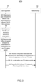
- FIG. 3 illustrates an example of a signaling diagram 300 for facilitating triggered PDCCH-ordered PRACH transmissions in multi-TRP scenarios.
- UE 310 and NE 320 may be similar to UE 1020 and NE 1010, as illustrated in FIG. 10 , according to certain example embodiments.
- UE 310 may determine that UE 310 will apply an indicated TCI state on the slot (e.g ., Slot_new TCI ) that is associated with a different TAG ID (TA value) than the previous slot (e.g., Slot_prevTCI ).
- an indicated TCI state on the slot e.g ., Slot_new TCI
- TA value TAG ID
- Slot_prevTCI TAG ID
- UE 310 may determine that UE 310 is not required to transmit UL transmissions on the at least first slot where a new TCI state is applied. For example, the determining may be based upon a TA value of the TAG ID associated with the new TCI being larger ( i.e. , more timing advance is required) than the TAG ID associated with the previous TCI state.
- UE 310 may determine that UE 310 is not required to transmit UL transmissions on the slot before the slot where the new TCI state is applied (i.e ., Slot_prevTCI ). For example, the determining may be based on the TA value of the TAG ID associated with the new TCI being larger ( i.e ., more timing advance is required) than the TAD ID associated with the previous TCI state.
- UE 310 may receive from NE 320 a configuration associated with prioritizing a UL transmission on the previous slot before the application of the new TCI state (e.g. , the previous slot before first slot after the BAT ends) and/or the first slot where the new TCI state (new beam) is applied.
- the UL transmission may include any of PUSCH, PUCCH, and SRS.
- prioritizing UL transmissions may refer to selecting/determining that if one (first) UL transmission is to be performed, the another (second) one is not performed. Prioritizing of UL transmission may be performed when UE 310 is unable to perform UL transmissions on slots (that are adjacent, for example, first and second slot) cannot be performed ( i.e. , UE 310 is able to perform one of the UL transmissions, for example, on the first or the second slot). Alternatively, prioritizing UL transmission may refer to selecting/determining that if one (second) UL transmission is to be performed, the first UL transmission is not performed.
- the prioritization (e.g. , selection) of UL transmission may be defined in the specification or it may be configured by the network.
- UE 310 may transmit to NE 320 UL on slots before the new TCI state is applied and/or on the first slot where the new TCI state is applied, if the TCI states are transmitted on different panels of UE 310.
- UE 310 may report to NE 320 the DL RS of the different TCI states to NE 320 with different capability index values in a L1-beam report (e.g ., L1-RSRP).
- L1-beam report e.g ., L1-RSRP
- different reported capability index values may indicate that different panels are used to transmit different TCI states.
- the different TCI states first and second
- UE 310 may be able to perform UL transmission on (adjacent) slots where different TCI states (previous and new) are applied.
- the different TCI states include DL RS that have been reported (or are to be reported) with an association of different UE (antenna) panel identifiers
- UE 310 may be able to perform UL transmission on (adjacent) slots where different TCI states (previous and new) are applied.
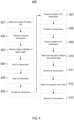
- FIG. 4 illustrates an example of a flow diagram of a method 400 that may be performed by a UE, such as UE 1020 illustrated in FIG. 10 , according to various example embodiments.
- the method may include determining that a first TCI state is to be applied in a first slot, and a second TCI state is to be applied in a second slot.
- the first TCI state may be associated with a first TAG ID
- a second TCI state may be associated with a second TAG ID different than the first TAG ID
- the second slot may succeed and be adjacent to the first slot.
- the method may further include, based upon the determining, transmitting or dropping at least one of at least one UL transmission in the first slot or at least one UL transmission in a second slot.
- the dropping of a transmission may refer to not transmitting on the slot where the transmission is dropped.
- the first TAG ID may be associated with a first TA value
- the second TAG ID may be associated with a second TA value different than the first TA value.
- the second TA value may be larger than the first TA value.
- the method may further include receiving, from a network entity, such as NE 1010 illustrated in FIG. 10 , while applying the first TCI state, a beam indication or beam switch indicating that the second TCI state for UL transmissions is to be applied for the UE.
- a network entity such as NE 1010 illustrated in FIG. 10
- the method may further include dropping the at least one UL transmission in the first slot, and at step 405, the method may further include dropping the at least one UL transmission in the second slot.
- the method may further include prioritizing the at least one UL transmission in the first slot over the at least one UL transmission in the second slot, and at step 407, the method may further include receiving, from the network entity, an indication indicating that the at least one UL transmission in the first slot is to be prioritized over the least one UL transmission in the second slot.
- the method may further include prioritizing the at least one UL transmission in the second slot over the at least one uplink transmission in the first slot, and at step 409, the method may further include receiving, from the network entity, an indication indicating that the at least one UL transmission in the second slot is to be prioritized over the UL transmission in the first slot.
- the method may further include determining that a first panel of the UE associated with the first TCI state is different than a second panel of the UE associated with the second TCI state.
- the method may further include, based on the determining, transmitting both the at least one UL transmission in the first slot and the at least one UL transmission in the second slot.
- the method may further include determining a capability value index associated with a DL RS corresponding to the first TCI state is different than a capability value index associated with a DL RS corresponding to the second TCI state.
- the method may further include, based on the determining, transmitting both the at least one UL transmission in the first slot and the at least one UL transmissions in the second slot.
- the at least one UL transmission in the first slot may include at least one of a PUSCH, a PUCCH, or a SRS and/or the at least one UL transmission in the second slot comprises at least one of a PUSCH, a PUCCH, or a SRS.
- FIG. 5 illustrates an example of a flow diagram of a method 500 that may be performed by a NE, such as NE 1010 illustrated in FIG. 10 , according to various example embodiments.
- the method may include determining that a first TCI state is to be applied in a first slot, and a second TCI state is to be applied in a second slot.
- the first TCI state may be associated with a first TAG ID
- a second TCI state may be associated with a second TAG ID different than the first TAG ID
- the second slot may succeed and be adjacent to the first slot.
- the method may further include, based upon the determining, transmitting or dropping at least one of at least one UL transmission in the first slot or at least one UL transmission in a second slot.
- the first TAG ID may be associated with a first TA value
- the second TAG ID may be associated with a second TA value different than the first TA value.
- the second TA value may be larger than the first TA value.
- the method may further include transmitting, to a user equipment, such as UE 1020 illustrated in FIG. 10 , while applying the first TCI state, a beam indication or beam switch indicating that the second TCI state for UL transmissions is to be applied for the UE.
- a user equipment such as UE 1020 illustrated in FIG. 10
- a beam indication or beam switch indicating that the second TCI state for UL transmissions is to be applied for the UE.
- the method may further include dropping the at least one UL transmission in the first slot, and at step 505, the method may further include dropping the at least one UL transmission in the second slot.
- the method may further include prioritizing the at least one UL transmission in the first slot over the at least one UL transmission in the second slot, and at step 507, the method may further include transmitting, to the user equipment, an indication indicating that the at least one UL transmission in the first slot is to be prioritized over the least one UL transmission in the second slot.
- the method may further include prioritizing the at least one UL transmission in the second slot over the at least one uplink transmission in the first slot, and at step 509, the method may further include transmitting, to a user equipment, an indication indicating that the at least one UL transmission in the second slot is to be prioritized over the UL transmission in the first slot.
- the method may further include determining that a first panel of the UE associated with the first TCI state is different than a second panel of the UE associated with the second TCI state.
- the method may further include, based on the determining, receiving both the at least one UL transmission in the first slot and the at least one UL transmission in the second slot.
- the method may further include determining a capability value index associated with a DL RS corresponding to the first TCI state is different than a capability value index associated with a DL RS corresponding to the second TCI state.
- the method may further include, based on the determining, receiving both the at least one UL transmission in the first slot and the at least one UL transmissions in the second slot.
- the at least one UL transmission in the first slot may include at least one of a PUSCH, a PUCCH, or a SRS and/or the at least one UL transmission in the second slot comprises at least one of a PUSCH, a PUCCH, or a SRS.
- the dropping of a transmission may refer to not transmitting on the slot where the transmission is dropped, not transmitting at least one symbol on the slot where the transmission is dropped, transmitting on at least one symbol (but not on all the symbols on the slot where the transmission is scheduled) on the slot where the transmission is dropped, not transmitting on at least one symbol on the start of the slot where the transmission is dropped, and/or not transmitting on at least one symbol at the end of the slot where the transmission is dropped.
- FIG. 6 illustrates an example of a signaling diagram 600 for facilitating triggered PDCCH-ordered PRACH transmissions in multi-TRP scenarios.
- Device 610 may be similar to NE 1010 or UE 1020, as illustrated in FIG. 10 , according to certain example embodiments.
- device 610 may determine that a BAT that would be applied by a UE, which may be device 610 or another device similar to UE 1020, may be determined based on the TAG ID association and determined conditions.
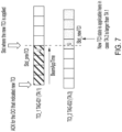
- device 610 may determine that a new TCI state is applicable one slot later than it would be if the timing would remain the same if the following condition is met. For example, as illustrated in FIG. 7 , the determination may be made if the TA value of the TAG ID associated with the new TCI is larger (i. e., more timing advance is required) than the TAD ID associated with the previous TCI state.
- device 610 may determine that the new TCI state is applicable in the first slot after the slot where the BAT ends ( i.e. , new TCI state is applied) where the slot is a DL slot ( i.e ., not UL slot). For example, the determination at 603 may be made if the TA value of the TAG ID associated with the new TCI is larger ( i.e ., more timing advance is required) than the TAD ID associated with the previous TCI state.
- the device may further determine (in any of the embodiments herein) whether the UL transmission is scheduled on both slots where the previous TCI state is applicable, and the new TCI state is applicable. If the device determines that on both slots the UL transmission is scheduled, it may apply the new TCI state according to the methods described herein.
- device 610 may determine that the new TCI state is applicable in the first slot after the slot where the BAT ends (or the BAT would end i.e ., new TCI state is or would be applied) where the UE is not scheduled with uplink transmission (e.g ., PUSCH, PUCCH and/or SRS) transmission ( i.e ., either DL/UL). For example, the determination may be made if the TA value of the TAG ID associated with the new TCI is larger ( i.e ., more timing advance is required) than the TAD ID associated with the previous TCI state.
- uplink transmission e.g ., PUSCH, PUCCH and/or SRS
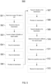
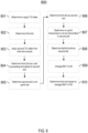
- FIG. 8 illustrates an example of a flow diagram of a method 800 that may be performed by a UE, such as UE 1020 illustrated in FIG. 10 , according to various example embodiments.
- the method may include determining that a first TCI state is to be applied in a first slot, and a second TCI state is to be applied in a second slot.
- the first TCI state may be associated with a first TAG ID
- a second TCI state may be associated with a second TAG ID different than the first TAG ID
- the second slot may succeed and be adjacent to the first slot.
- the method may further include, based upon the determining, determining a third slot.
- the second TCI state may firstly be applied in the third slot.
- the method may further include applying the second TCI state from the third slot onward.
- the first TAG ID may be associated with a first TA value
- the second TAG ID may be associated with a second TA value different than the first TA value.
- the second TA value may be larger than the first TA value.
- the method may further include determining the third slot as a slot succeeding and adjacent to the second slot.
- the method may further include determining that the second slot is not an uplink slot, and at step 806, the method may further include, based on the determining, determining the third slot as the second slot.
- the method may further include determining no uplink transmission (e.g ., PUSCH, PUCCH, SRS) is to be transmitted in the second slot, and at step 808, the method may further include, based on the determining, determining the third slot as the second slot.
- determining no uplink transmission e.g ., PUSCH, PUCCH, SRS
- the method may further include changing a BAT of the UE, and at step 810, the method may further include determining the third slot based on the changed BAT of the UE.
- changing the BAT may include adding a number of symbols into the BAT.
- FIG. 9 illustrates an example of a flow diagram of a method 900 that may be performed by a NE, such as NE 1010 illustrated in FIG. 10 , according to various example embodiments.
- the method may include determining that a first TCI state is to be applied in a first slot, and a second TCI state is to be applied in a second slot.
- the first TCI state may be associated with a first TAG ID
- a second TCI state may be associated with a second TAG ID different than the first TAG ID
- the second slot may succeed and be adjacent to the first slot.
- the method may further include, based upon the determining, determining a third slot.
- the second TCI state may firstly be applied in the third slot.
- the method may further include applying the second TCI state from the third slot onward.
- the first TAG ID may be associated with a first TA value
- the second TAG ID may be associated with a second TA value different than the first TA value.
- the second TA value may be larger than the first TA value.
- the method may further include determining the third slot as a slot succeeding and adjacent to the second slot.
- the method may further include determining that the second slot is not an uplink slot, and at step 906, the method may further include, based on the determining, determining the third slot as the second slot.
- the method may further include determining no PUSCH is to be transmitted in the second slot, and at step 808, the method may further include, based on the determining, determining the third slot as the second slot.
- the method may further include changing a BAT of a UE, such as UE 1020 illustrated in FIG. 10 , and at step 910, the method may further include determining the third slot based on the changed BAT of the UE.
- changing the BAT may include adding a number of symbols into the BAT.
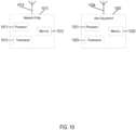
- FIG. 10 illustrates an example of a system according to certain example embodiments.
- a system may include multiple devices, such as, for example, NE 1010 and/or UE 1020.
- NE 1010 may be one or more of a base station (e.g ., 3G UMTS NodeB, 4G LTE Evolved NodeB, or 5G NR Next Generation NodeB), a serving gateway, a server, and/or any other access node or combination thereof.
- a base station e.g ., 3G UMTS NodeB, 4G LTE Evolved NodeB, or 5G NR Next Generation NodeB
- serving gateway e.g., a serving gateway, a server, and/or any other access node or combination thereof.
- NE 1010 may further include at least one gNB-centralized unit (CU), which may be associated with at least one gNB-distributed unit (DU).
- the at least one gNB-CU and the at least one gNB-DU may be in communication via at least one F1 interface, at least one X n -C interface, and/or at least one NG interface via a 5 th generation core (5GC).
- CU gNB-centralized unit
- DU gNB-distributed unit
- the at least one gNB-CU and the at least one gNB-DU may be in communication via at least one F1 interface, at least one X n -C interface, and/or at least one NG interface via a 5 th generation core (5GC).
- 5GC 5 th generation core
- UE 1020 may include one or more of a mobile device, such as a mobile phone, smart phone, personal digital assistant (PDA), tablet, or portable media player, digital camera, pocket video camera, video game console, navigation unit, such as a global positioning system (GPS) device, desktop or laptop computer, single-location device, such as a sensor or smart meter, or any combination thereof.
- a mobile device such as a mobile phone, smart phone, personal digital assistant (PDA), tablet, or portable media player, digital camera, pocket video camera, video game console, navigation unit, such as a global positioning system (GPS) device, desktop or laptop computer, single-location device, such as a sensor or smart meter, or any combination thereof.
- GPS global positioning system
- NE 1010 and/or UE 1020 may be one or more of a citizens broadband radio service device (CBSD).
- CBSD citizens broadband radio service device
- NE 1010 and/or UE 1020 may include at least one processor, respectively indicated as 1011 and 1021.
- Processors 1011 and 1021 may be embodied by any computational or data processing device, such as a central processing unit (CPU), application specific integrated circuit (ASIC), or comparable device.
- the processors may be implemented as a single controller, or a plurality of controllers or processors.
- At least one memory may be provided in one or more of the devices, as indicated at 1012 and 1022.
- the memory may be fixed or removable.
- the memory may include computer program instructions or computer code contained therein.
- Memories 1012 and 1022 may independently be any suitable storage device, such as a non-transitory computer-readable medium.
- the term "non-transitory,” as used herein, may correspond to a limitation of the medium itself (i.e., tangible, not a signal) as opposed to a limitation on data storage persistency (e.g ., random access memory (RAM) vs. read-only memory (ROM)).
- RAM random access memory
- ROM read-only memory
- a hard disk drive (HDD), random access memory (RAM), flash memory, or other suitable memory may be used.
- Processors 1011 and 1021, memories 1012 and 1022, and any subset thereof, may be configured to provide means corresponding to the various blocks of FIGs. 3-9 .
- the devices may also include positioning hardware, such as GPS or micro electrical mechanical system (MEMS) hardware, which may be used to determine a location of the device.
- MEMS micro electrical mechanical system
- Other sensors are also permitted, and may be configured to determine location, elevation, velocity, orientation, and so forth, such as barometers, compasses, and the like.
- transceivers 1013 and 1023 may be provided, and one or more devices may also include at least one antenna, respectively illustrated as 1014 and 1024.
- the device may have many antennas, such as an array of antennas configured for multiple input multiple output (MIMO) communications, or multiple antennas for multiple RATs. Other configurations of these devices, for example, may be provided.
- Transceivers 1013 and 1023 may be a transmitter, a receiver, both a transmitter and a receiver, or a unit or device that may be configured both for transmission and reception.
- the memory and the computer program instructions may be configured, with the processor for the particular device, to cause a hardware apparatus, such as UE, to perform any of the processes described above (i.e ., FIGs. 3-9 ). Therefore, in certain example embodiments, a non-transitory computer-readable medium may be encoded with computer instructions that, when executed in hardware, perform a process such as one of the processes described herein. Alternatively, certain example embodiments may be performed entirely in hardware.
- circuitry also covers an implementation of merely a hardware circuit or processor (or multiple processors) or portion of a hardware circuit or processor and its (or their) accompanying software and/or firmware.
- circuitry also covers, for example and if applicable to the particular claim element, a baseband integrated circuit or processor integrated circuit for a mobile device or a similar integrated circuit in server, a cellular network device, or other computing or network device.
- FIG. 11 illustrates an example of a 5G network and system architecture according to certain example embodiments. Shown are multiple network functions that may be implemented as software operating as part of a network device or dedicated hardware, as a network device itself or dedicated hardware, or as a virtual function operating as a network device or dedicated hardware.
- the NE and UE illustrated in FIG. 11 may be similar to NE 1010 and UE 1020, respectively.
- the user plane function (UPF) may provide services such as intra-RAT and inter-RAT mobility, routing and forwarding of data packets, inspection of packets, user plane quality of service (QoS) processing, buffering of DL packets, and/or triggering of DL data notifications.
- the application function (AF) may primarily interface with the core network to facilitate application usage of traffic routing and interact with the policy framework.
- processors 1011 and 1021, and memories 1012 and 1022 may be included in or may form a part of processing circuitry or control circuitry.
- transceivers 1013 and 1023 may be included in or may form a part of transceiving circuitry.
- an apparatus may include means for performing a method, a process, or any of the variants discussed herein.
- the means may include one or more processors, memory, controllers, transmitters, receivers, and/or computer program code for causing the performance of the operations.
- apparatus 1020 may be controlled by memory 1022 and processor 1021 to determine that a first TCI state is to be applied in a first slot and a second TCI state is to be applied in a second slot; based upon the determining, determine a third slot; and apply the second TCI state from the third slot onward.
- the first TCI state is associated with a first TAG ID
- a second TCI state is associated with a second TAG ID different than the first TAG ID
- the second slot is succeeding and adjacent to the first slot.
- the second TCI state is firstly to be applied in the third slot.
- Certain example embodiments may be directed to an apparatus that includes means for performing any of the methods described herein including, for example, means for determining that a first TCI state is to be applied in a first slot and a second TCI state is to be applied in a second slot; means for, based upon the determining, determine a third slot; and means for applying the second TCI state from the third slot onward.
- the first TCI state is associated with a first TAG ID
- a second TCI state is associated with a second TAG ID different than the first TAG ID
- the second slot is succeeding and adjacent to the first slot.
- the second TCI state is firstly to be applied in the third slot.
- apparatus 1010 may be controlled by memory 1012 and processor 1011 to determine that a first TCI state is to be applied in a first slot and a second TCI state is to be applied in a second slot; based upon the determining, determine a third slot; and apply, at a user equipment, the second TCI state from the third slot onward.
- the first TCI state is associated with a first TAG ID
- a second TCI state is associated with a second TAG ID different than the first TAG ID
- the second slot is succeeding and adjacent to the first slot.
- the second TCI state is firstly to be applied in the third slot.
- Certain example embodiments may be directed to an apparatus that includes means for performing any of the methods described herein including, for example, means for determining that a first TCI state is to be applied in a first slot and a second TCI state is to be applied in a second slot; based upon the determining, determining a third slot; and applying, at a user equipment, the second TCI state from the third slot onward.
- the first TCI state is associated with a first TAG ID
- a second TCI state is associated with a second TAG ID different than the first TAG ID
- the second slot is succeeding and adjacent to the first slot.
- the second TCI state is firstly to be applied in the third slot.
Landscapes
- Engineering & Computer Science (AREA)
- Signal Processing (AREA)
- Computer Networks & Wireless Communication (AREA)
- Mobile Radio Communication Systems (AREA)
Applications Claiming Priority (1)
| Application Number | Priority Date | Filing Date | Title |
|---|---|---|---|
| US202363456667P | 2023-04-03 | 2023-04-03 |
Publications (1)
| Publication Number | Publication Date |
|---|---|
| EP4443992A1 true EP4443992A1 (de) | 2024-10-09 |
Family
ID=90571683
Family Applications (1)
| Application Number | Title | Priority Date | Filing Date |
|---|---|---|---|
| EP24167626.1A Pending EP4443992A1 (de) | 2023-04-03 | 2024-03-28 | Mehrfach-zeitvorlaufbetrieb |
Country Status (2)
| Country | Link |
|---|---|
| US (1) | US20240334404A1 (de) |
| EP (1) | EP4443992A1 (de) |
Citations (1)
| Publication number | Priority date | Publication date | Assignee | Title |
|---|---|---|---|---|
| US20220330192A1 (en) * | 2020-02-24 | 2022-10-13 | Zte Corporation | Methods, apparatus and systems for configuring timing advance informaiton in a wireless communication |
Family Cites Families (10)
| Publication number | Priority date | Publication date | Assignee | Title |
|---|---|---|---|---|
| KR102292994B1 (ko) * | 2017-03-23 | 2021-08-26 | 삼성전자 주식회사 | 무선 통신 시스템에서 타이밍 조정 방법 및 장치 |
| US12408174B2 (en) * | 2019-09-15 | 2025-09-02 | Qualcomm Incorporated | Transmission configuration indicator state activation techniques for carrier aggregation |
| KR102688462B1 (ko) * | 2019-09-18 | 2024-07-26 | 삼성전자주식회사 | 네트워크 협력 통신을 위한 상향링크 반복 전송 방법 및 장치 |
| US20210153193A1 (en) * | 2019-11-14 | 2021-05-20 | Asustek Computer Inc. | Method and apparatus for uplink timing determination in a wireless communication system |
| KR20210103293A (ko) * | 2020-02-13 | 2021-08-23 | 삼성전자주식회사 | 네트워크 협력통신을 위한 상향링크 제어 정보 반복 전송 방법 및 장치 |
| US11985617B2 (en) * | 2020-09-04 | 2024-05-14 | Qualcomm Incorporated | Full duplex timing advance enhancements |
| JP7718900B2 (ja) * | 2021-08-04 | 2025-08-05 | 株式会社Soken | 通信装置、基地局及び通信方法 |
| CN116032442B (zh) * | 2021-10-27 | 2025-07-25 | 维沃移动通信有限公司 | 波束应用时间确定方法、装置及通信设备 |
| KR20240134308A (ko) * | 2022-01-11 | 2024-09-09 | 엘지전자 주식회사 | 무선 통신 시스템에서 상향링크 송수신 방법 및 장치 |
| CN118140561A (zh) * | 2022-07-28 | 2024-06-04 | 中兴通讯股份有限公司 | 用于调整上行传输定时的方案 |
-
2024
- 2024-03-28 EP EP24167626.1A patent/EP4443992A1/de active Pending
- 2024-04-02 US US18/624,459 patent/US20240334404A1/en active Pending
Patent Citations (1)
| Publication number | Priority date | Publication date | Assignee | Title |
|---|---|---|---|---|
| US20220330192A1 (en) * | 2020-02-24 | 2022-10-13 | Zte Corporation | Methods, apparatus and systems for configuring timing advance informaiton in a wireless communication |
Non-Patent Citations (2)
| Title |
|---|
| CATT: "On Two TAs for UL multi-DCI for multi-TRP operation", vol. RAN WG1, no. e-Meeting; 20221010 - 20221019, 30 September 2022 (2022-09-30), XP052276866, Retrieved from the Internet <URL:https://ftp.3gpp.org/tsg_ran/WG1_RL1/TSGR1_110b-e/Docs/R1-2208946.zip R1-2208946.docx> [retrieved on 20220930] * |
| NEC: "Discussion on two TAs for multi-DCI", vol. RAN WG1, no. e-Meeting; 20221010 - 20221019, 30 September 2022 (2022-09-30), XP052277057, Retrieved from the Internet <URL:https://ftp.3gpp.org/tsg_ran/WG1_RL1/TSGR1_110b-e/Docs/R1-2209139.zip R1-2209139.docx> [retrieved on 20220930] * |
Also Published As
| Publication number | Publication date |
|---|---|
| US20240334404A1 (en) | 2024-10-03 |
Similar Documents
| Publication | Publication Date | Title |
|---|---|---|
| EP4018772B1 (de) | Wiederherstellung von funkverbindungsfehlern | |
| EP3949550A1 (de) | Sendeleistung für duale konnektivität | |
| KR20220002512A (ko) | 향상된 랜덤 액세스 절차의 시스템 및 방법 | |
| CN114342535A (zh) | 上行信号的发送和接收方法以及装置 | |
| US12185376B2 (en) | Spectrum extension for initial access | |
| US12568524B2 (en) | Random access method, and electronic device and storage medium | |
| US20250247196A1 (en) | Flexible tci state indication under unified tci framework | |
| US12075415B2 (en) | Sidelink aided scalable initial access for massive IIoT support | |
| EP3944538A1 (de) | Meldung von hybrider automatischer wiederholungsanforderung für downlink-semipersistente zeitplanungsdatenübertragung | |
| WO2020074069A1 (en) | Enhanced scheduling request transmissions in wireless networks | |
| EP4443992A1 (de) | Mehrfach-zeitvorlaufbetrieb | |
| US20240334405A1 (en) | Multiple timing advance operation | |
| WO2024092618A1 (en) | Method and apparatus for ntn coverage enhancement for pucch and pusch | |
| EP4346308A1 (de) | Optimierung kleiner datenübertragung unter verwendung eines direktzugriffskanals für benutzergerät mit reduzierter kapazität | |
| US20240340867A1 (en) | Time domain resource allocation of random access message for reduced capability devices | |
| US12445222B2 (en) | Extended channel quality report for 16-quadrature amplitude modulation in narrowband Internet of Things | |
| WO2026031094A1 (en) | Methods for ue-initiated beam report on dynamically-granted pusch in wireless communications | |
| EP4465712A1 (de) | Verfahren zur sidelink-positionierungsreferenzsignalmessung durch kombination von sidelink-positionierungsreferenzsignalressourcen | |
| WO2024092636A1 (en) | Method and apparatus for ntn coverage enhancement with pusch dmrs bundling | |
| WO2024072413A1 (en) | Method for supporting changing transmission parameters of multi-physical downlink shared channel/physical uplink shared channel for extended reality applications | |
| WO2025210452A1 (en) | User equipment event-driven beam reports for group based beam reporting | |
| WO2025210441A1 (en) | User equipment event-driven beam reports for group based beam reporting | |
| WO2025093402A1 (en) | Methods for measurement reporting via configuration update | |
| WO2026073702A1 (en) | Beam-group power scaling | |
| EP4501009A1 (de) | Multiplexing von uplink-steuerungsinformationen auf einem physikalischen uplink-steuerkanal |
Legal Events
| Date | Code | Title | Description |
|---|---|---|---|
| PUAI | Public reference made under article 153(3) epc to a published international application that has entered the european phase |
Free format text: ORIGINAL CODE: 0009012 |
|
| STAA | Information on the status of an ep patent application or granted ep patent |
Free format text: STATUS: THE APPLICATION HAS BEEN PUBLISHED |
|
| AK | Designated contracting states |
Kind code of ref document: A1 Designated state(s): AL AT BE BG CH CY CZ DE DK EE ES FI FR GB GR HR HU IE IS IT LI LT LU LV MC ME MK MT NL NO PL PT RO RS SE SI SK SM TR |
|
| STAA | Information on the status of an ep patent application or granted ep patent |
Free format text: STATUS: REQUEST FOR EXAMINATION WAS MADE |
|
| 17P | Request for examination filed |
Effective date: 20250409 |