EP4445818A2 - Dispositif de nettoyage de sol, en particulier dispositif de nettoyage de sol par aspiration et récure, présentant des propriétés de manoeuvre améliorées - Google Patents
Dispositif de nettoyage de sol, en particulier dispositif de nettoyage de sol par aspiration et récure, présentant des propriétés de manoeuvre améliorées Download PDFInfo
- Publication number
- EP4445818A2 EP4445818A2 EP24196445.1A EP24196445A EP4445818A2 EP 4445818 A2 EP4445818 A2 EP 4445818A2 EP 24196445 A EP24196445 A EP 24196445A EP 4445818 A2 EP4445818 A2 EP 4445818A2
- Authority
- EP
- European Patent Office
- Prior art keywords
- guide part
- floor
- pivot axis
- cleaning device
- floor cleaning
- Prior art date
- Legal status (The legal status is an assumption and is not a legal conclusion. Google has not performed a legal analysis and makes no representation as to the accuracy of the status listed.)
- Pending
Links
- 238000004140 cleaning Methods 0.000 title claims abstract description 175
- 230000001976 improved effect Effects 0.000 title description 5
- 230000008093 supporting effect Effects 0.000 claims description 17
- 230000000750 progressive effect Effects 0.000 claims description 7
- 230000005484 gravity Effects 0.000 claims description 6
- 230000001154 acute effect Effects 0.000 claims description 4
- 238000006073 displacement reaction Methods 0.000 claims description 3
- 230000000694 effects Effects 0.000 abstract description 54
- XLYOFNOQVPJJNP-UHFFFAOYSA-N water Substances O XLYOFNOQVPJJNP-UHFFFAOYSA-N 0.000 description 17
- 238000011161 development Methods 0.000 description 16
- 230000018109 developmental process Effects 0.000 description 16
- 230000008901 benefit Effects 0.000 description 10
- 230000008878 coupling Effects 0.000 description 6
- 238000010168 coupling process Methods 0.000 description 6
- 238000005859 coupling reaction Methods 0.000 description 6
- 239000012530 fluid Substances 0.000 description 5
- 239000012459 cleaning agent Substances 0.000 description 4
- 230000006835 compression Effects 0.000 description 4
- 238000007906 compression Methods 0.000 description 4
- 239000007788 liquid Substances 0.000 description 4
- 230000007246 mechanism Effects 0.000 description 4
- 230000007935 neutral effect Effects 0.000 description 4
- 238000007789 sealing Methods 0.000 description 4
- 208000002740 Muscle Rigidity Diseases 0.000 description 3
- 230000009471 action Effects 0.000 description 3
- 230000000903 blocking effect Effects 0.000 description 3
- 238000000034 method Methods 0.000 description 3
- 230000008569 process Effects 0.000 description 3
- 241001295925 Gegenes Species 0.000 description 2
- 238000013016 damping Methods 0.000 description 2
- 230000002349 favourable effect Effects 0.000 description 2
- 239000002245 particle Substances 0.000 description 2
- 230000008092 positive effect Effects 0.000 description 2
- 230000036316 preload Effects 0.000 description 2
- 230000003014 reinforcing effect Effects 0.000 description 2
- 238000009420 retrofitting Methods 0.000 description 2
- 238000010521 absorption reaction Methods 0.000 description 1
- 230000003213 activating effect Effects 0.000 description 1
- 230000002730 additional effect Effects 0.000 description 1
- 230000005540 biological transmission Effects 0.000 description 1
- 230000008859 change Effects 0.000 description 1
- 230000003247 decreasing effect Effects 0.000 description 1
- 230000006872 improvement Effects 0.000 description 1
- 230000010354 integration Effects 0.000 description 1
- 230000003993 interaction Effects 0.000 description 1
- 239000002655 kraft paper Substances 0.000 description 1
- 230000007774 longterm Effects 0.000 description 1
- 239000000463 material Substances 0.000 description 1
- 239000002184 metal Substances 0.000 description 1
- 239000000203 mixture Substances 0.000 description 1
- 230000001141 propulsive effect Effects 0.000 description 1
- 239000007787 solid Substances 0.000 description 1
- 230000000087 stabilizing effect Effects 0.000 description 1
- 210000002105 tongue Anatomy 0.000 description 1
- 230000007704 transition Effects 0.000 description 1
- 208000008918 voyeurism Diseases 0.000 description 1
Images


Classifications
-
- A—HUMAN NECESSITIES
- A47—FURNITURE; DOMESTIC ARTICLES OR APPLIANCES; COFFEE MILLS; SPICE MILLS; SUCTION CLEANERS IN GENERAL
- A47L—DOMESTIC WASHING OR CLEANING; SUCTION CLEANERS IN GENERAL
- A47L11/00—Machines for cleaning floors, carpets, furniture, walls, or wall coverings
- A47L11/29—Floor-scrubbing machines characterised by means for taking-up dirty liquid
- A47L11/30—Floor-scrubbing machines characterised by means for taking-up dirty liquid by suction
- A47L11/302—Floor-scrubbing machines characterised by means for taking-up dirty liquid by suction having rotary tools
- A47L11/305—Floor-scrubbing machines characterised by means for taking-up dirty liquid by suction having rotary tools the tools being disc brushes
-
- A—HUMAN NECESSITIES
- A47—FURNITURE; DOMESTIC ARTICLES OR APPLIANCES; COFFEE MILLS; SPICE MILLS; SUCTION CLEANERS IN GENERAL
- A47L—DOMESTIC WASHING OR CLEANING; SUCTION CLEANERS IN GENERAL
- A47L11/00—Machines for cleaning floors, carpets, furniture, walls, or wall coverings
- A47L11/40—Parts or details of machines not provided for in groups A47L11/02 - A47L11/38, or not restricted to one of these groups, e.g. handles, arrangements of switches, skirts, buffers, levers
- A47L11/4036—Parts or details of the surface treating tools
- A47L11/4038—Disk shaped surface treating tools
-
- A—HUMAN NECESSITIES
- A47—FURNITURE; DOMESTIC ARTICLES OR APPLIANCES; COFFEE MILLS; SPICE MILLS; SUCTION CLEANERS IN GENERAL
- A47L—DOMESTIC WASHING OR CLEANING; SUCTION CLEANERS IN GENERAL
- A47L11/00—Machines for cleaning floors, carpets, furniture, walls, or wall coverings
- A47L11/40—Parts or details of machines not provided for in groups A47L11/02 - A47L11/38, or not restricted to one of these groups, e.g. handles, arrangements of switches, skirts, buffers, levers
- A47L11/4061—Steering means; Means for avoiding obstacles; Details related to the place where the driver is accommodated
-
- A—HUMAN NECESSITIES
- A47—FURNITURE; DOMESTIC ARTICLES OR APPLIANCES; COFFEE MILLS; SPICE MILLS; SUCTION CLEANERS IN GENERAL
- A47L—DOMESTIC WASHING OR CLEANING; SUCTION CLEANERS IN GENERAL
- A47L11/00—Machines for cleaning floors, carpets, furniture, walls, or wall coverings
- A47L11/40—Parts or details of machines not provided for in groups A47L11/02 - A47L11/38, or not restricted to one of these groups, e.g. handles, arrangements of switches, skirts, buffers, levers
- A47L11/4063—Driving means; Transmission means therefor
- A47L11/4066—Propulsion of the whole machine
-
- A—HUMAN NECESSITIES
- A47—FURNITURE; DOMESTIC ARTICLES OR APPLIANCES; COFFEE MILLS; SPICE MILLS; SUCTION CLEANERS IN GENERAL
- A47L—DOMESTIC WASHING OR CLEANING; SUCTION CLEANERS IN GENERAL
- A47L11/00—Machines for cleaning floors, carpets, furniture, walls, or wall coverings
- A47L11/40—Parts or details of machines not provided for in groups A47L11/02 - A47L11/38, or not restricted to one of these groups, e.g. handles, arrangements of switches, skirts, buffers, levers
- A47L11/4072—Arrangement of castors or wheels
-
- F—MECHANICAL ENGINEERING; LIGHTING; HEATING; WEAPONS; BLASTING
- F16—ENGINEERING ELEMENTS AND UNITS; GENERAL MEASURES FOR PRODUCING AND MAINTAINING EFFECTIVE FUNCTIONING OF MACHINES OR INSTALLATIONS; THERMAL INSULATION IN GENERAL
- F16C—SHAFTS; FLEXIBLE SHAFTS; ELEMENTS OR CRANKSHAFT MECHANISMS; ROTARY BODIES OTHER THAN GEARING ELEMENTS; BEARINGS
- F16C11/00—Pivots; Pivotal connections
- F16C11/04—Pivotal connections
Definitions
- German utility model specification DE 20 2013 012 528 U9 describes a floor cleaning device in which an advantageous arrangement of two cleaning tools in conjunction with a suction bar improves the cleaning and propulsion function compared to DE 10 2009 028 944 A1 improved.
- the document DE 10 2016 208 895 A1 describes a floor cleaning device with a space-saving arrangement of drive components in the floor unit.
- the granted European patent EP 3 031 378 B1 describes a floor cleaning device which provides provisions to enable the device to be moved between an operating position and a space-saving transport or storage position as required.
- a floor cleaning device of the type described above in which it is provided that in a maneuvering operating state the guide part the first pivot axis can be pivoted relative to the floor unit, wherein the guide part can be fixed or temporarily supported in the first pivot axis plane relative to the floor unit or to the floor, wherein as a result of the pivoting movement of the guide part about the first pivot axis with the mediation of the support of the guide part in the pivot axis plane, the propulsion effect and/or a maneuvering movement of an operator causes a rotational moment of the floor unit on the floor surface which favors the maneuvering of the floor cleaning device and preferably acts about a rotational axis substantially perpendicular to the floor surface.
- Such a maneuvering movement can, for example, be a slight decentralized counter-holding of the operator on the guide part against the propulsion effect, which together with the propulsion effect on the floor unit leads to the rotational moment of the floor unit on the floor surface.
- the swiveling takes place in a guided manner around the first swivel range and that the fixed swivel axis or the virtual swivel axis, i.e. the swivel axis that is currently effective in the respective phase of the swivel but changes depending on the degree of swiveling around the swivel range, lies in the first swivel axis plane.
- the floor cleaning device is characterized in that in a maneuvering operating state the guide part is fixed or can be temporarily supported or permanently supported in relation to the floor unit in a manner explained in more detail below, and this is done completely or at least partially, so that the weight of the guide part acts on the floor part and ultimately on the floor to be cleaned via the support. It is therefore no longer necessary for an operator to take on the weight of the guide part in the same way as is the case with the prior art when the guide part is tilted backwards (i.e. towards the operator) during the maneuvering operating state in the operating device according to the invention (i.e. towards the operator) and is thereby supported or when the guide part is already positioned backwards with its handle section due to the machine structure.
- Weight force can be reduced via the support. Only partial support of the weight force is already advantageous.
- the complete or at least partial introduction of the weight force of the guide part into the floor unit during the maneuvering operating state via the support offers additional advantages in terms of the maneuvering properties of the floor cleaning device according to the invention, depending on where the portion of the weight force taken over via the support acts on the floor unit.
- the inclination of the guide part with respect to the direction of advance relates, for example, to a guide part longitudinal axis which runs essentially orthogonal to the first pivot axis in the longitudinal direction of the guide part and extends through an action line which is determined by points of attack for an operator on the guide part for maneuvering the floor cleaning device, for example by handles.
- the first swivel joint on the ground unit is permanently fixed about the first swivel axis or can be locked in predetermined positions that determine the alignment of the first longitudinal axis to the direction vector defining the direction of advance in the maneuvering operating state.
- the first swivel joint can be permanently locked about the first swivel axis in a specific alignment or in predetermined positions.
- the weight of the guide part can then be supported in the ground unit via the permanent or temporary locking. This also results in the advantageous maneuvering properties already described.
- the joint arrangement is designed with a second swivel joint, which has a second swivel range with a fixed or virtual second swivel axis and allows a swivel movement of the guide part relative to the floor unit around the second swivel range.
- the second swivel axis runs essentially parallel to the floor surface and transversely to the first swivel axis.
- Floor cleaning devices with two swivel joints with swivel axes running transversely, in particular orthogonally, to one another are already known from the prior art.
- the document DE 10 2009 028 944 A1 such a joint arrangement with a double swivel joint.
- Such a joint arrangement does indeed improve the maneuverability compared to the prior art, but has the disadvantage that in the maneuvering mode a not inconsiderable portion of the weight of the guide part must be borne by the operator, as explained above.
- the present invention provides that the joint arrangement can be brought into a state via the support permanently or, if necessary, temporarily in which this disadvantage is overcome.
- the support the joint arrangement can be supported directly on or in the joint arrangement.
- the joint arrangement can be supported by attaching the support device to the guide part, with the support device then being supported on the floor unit or directly on the floor.
- the joint arrangement can be supported by attaching the support device to the floor unit, with the support device then supporting the guide part.
- an advantageous embodiment of the invention provides that the joint arrangement is functionally assigned a support device which, in the maneuvering operating state, supports the joint arrangement with the first swivel joint relative to the base unit at least temporarily and/or at least partially in the maneuvering operating state.
- a support device can, for example, be attached manually, switched on electrically or electromagnetically, or be permanently present, possibly also with a linear or progressive or degressive support characteristic.
- the joint arrangement can be supported directly on the joint arrangement or indirectly by attaching the support device to the guide part or to the base unit.
- a simple mechanical design variant provides that the support device can be locked at least temporarily in at least one locking position, preferably in at least two, particularly preferably in at least three locking positions.
- the support device can be locked in a continuously variable manner.
- the support device it is possible for the support device to be rigid. This can be achieved, for example, using a support strut, a support angle, a supporting catch fork or a locking bracket.
- a further development of the invention can provide that a damper element is assigned to the support device. This measure can be used, for example, to achieve a gentle, dampened transition between an unsupported and a partially or fully supported state.
- a further development of the invention provides for the guide part not only to be supported in the first pivot axis plane, but also to provide a further support device associated with the first pivot axis, which is designed to at least partially support the guide part when pivoting about the first pivot axis from the first pivot axis plane relative to the base unit from a predetermined or predeterminable pivot angle.
- the guide part can also be supported when pivoting sideways at least from a certain pivot angle.
- the support can be provided as described above, for example rigidly, spring-loaded and/or damped. Reference is made to the above statements on support with respect to the first pivot axis, which at this point also apply analogously to support with respect to a movement about the second pivot axis.
- the joint arrangement has a connecting element which connects the first pivot joint to the second pivot joint, wherein the connecting element can be pivoted relative to the base unit about the second pivot axis and the guide part relative to the connecting element can be pivoted about the first pivot axis.
- the connecting element can be supported relative to the base unit.
- the support device for support in the first pivot axis plane is thus coupled to the connecting element in order to ensure - even in the case of effective support - continued good mobility of the guide part about the first pivot axis.
- the respective support device is assigned to the connecting element and comprises a support element which, in the maneuvering operating state, contacts the ground unit in a supporting manner.
- the support device is assigned an adhesion element, in particular a magnet, which is designed to secure the support device during support against pivoting against the support direction and/or transversely to the support direction until a force threshold value is exceeded.
- the support device can be held in a supporting operating position in order to prevent an undesired release of the support effect.
- the support device preferably via the adhesion element, provides a substantially positive and/or non-positive connection between the support device and the guide part or the base unit.
- An at least partial positive connection can be provided, for example, by providing a simple recess or trough into which the support device engages.
- the second pivot axis is aligned substantially perpendicularly to the first pivot axis.
- the guide part can comprise a longitudinal axis which is preferably oriented perpendicularly to the first pivot axis and optionally perpendicularly to the second pivot axis.
- the mass distribution can also be influenced by an operator pivoting the guide part around the second pivot axis.
- the entire floor cleaning device can be "tilted” backwards to a greater or lesser extent by pulling the guide part backwards against the support effect. This measure relieves the load on the front area of the floor cleaning device, for example the cleaning tools or drive wheels that generate the propulsion, while mediating the support effect, which can make maneuvering easier.
- the "tilting” mentioned can be in the range of a few angular minutes or a few angular degrees.
- the floor cleaning device according to the invention at least optionally provides a propulsion effect on the floor unit.
- the at least one tool is designed to contact the floor surface in the operating state and at least partially generate the propulsion.
- the effect according to the invention is already achieved - at least to a limited extent - by the fact that the tools rotating in opposite directions to one another greatly reduce the friction between the floor cleaning device and the surface even without a propulsion effect. If the floor cleaning device is then pushed forward manually and the guide part is pivoted about the first pivot axis as described above, the favorable rotational moment of the floor unit described at the beginning can be brought about from this forward movement alone by the forward movement and the associated inertia of the floor cleaning device.
- the tool of the floor unit comprises at least one rotationally driven brush with a rotation axis which, in the operating state, is aligned substantially parallel to the floor surface.
- a first brush comprises a first axis of rotation which, in the operating state, is aligned at a slight incline with respect to a perpendicular to the floor surface
- a second of the brushes comprises a second axis of rotation which, in the operating state, is also aligned at a slight incline with respect to a perpendicular to the floor surface, wherein the first and second brushes are designed to rotate in opposite directions.
- the directions of rotation can be freely selected.
- the first rotation axis and the second rotation axis are inclined by 0.8° to 5°, preferably by about 1.5°, relative to the vertical.
- the inclination can be adjustable by an operator using a suitable mechanism.
- the floor cleaning device can further provide that the floor unit comprises at least one drive body, for example in the form of a wheel, a barrel or a roller-shaped cylinder, which in the operating state contacts the floor surface and which is designed to generate the propulsion at least temporarily and/or at least partially.
- the floor unit comprises at least one drive body, for example in the form of a wheel, a barrel or a roller-shaped cylinder, which in the operating state contacts the floor surface and which is designed to generate the propulsion at least temporarily and/or at least partially.
- the floor cleaning device further comprises a suction unit which is designed to suck up particles and/or liquid or generally dirty water from the floor surface.
- the suction unit can comprise at least one suction turbine which is arranged on the floor unit or on the guide part or is designed separately from these and is designed to generate a negative pressure.
- the suction effect can be supported or reinforced by a linear or rounded suction bar arranged on the rear side of the floor cleaning device facing the user.
- This suction bar can have one or more sealing lips.
- the suction bar and/or sealing lips can provide a frictional force relative to the floor surface, which can be advantageous in absorbing transverse forces introduced into the floor unit via the guide part. Transverse forces can also be absorbed via guide or drive wheels.
- the floor cleaning device can comprise at least one collecting container which is designed to collect the sucked-up particles and/or the liquid used for cleaning, wherein the collecting container is arranged in particular detachably on the guide part or the floor unit.
- the floor cleaning device can comprise a cleaning agent container which is designed to provide a cleaning agent to the at least one tool, preferably via a feed device, wherein the cleaning agent container is arranged on the floor unit or on the guide part.
- the floor cleaning device can comprise a clean water container which is designed to provide clean water to the at least one tool, preferably via a supply device, wherein the clean water container is arranged on the floor unit or on the guide part.
- the collection container, the cleaning agent container and the clean water container can be designed in groups or as an integral whole.
- the floor cleaning device can be brought into a parking state, wherein in the parking state the floor unit can be displaced relative to the guide part into a space-saving parking position and can be locked in this.
- a further development of the invention provides that the support device is designed to completely lock the guide part relative to the base unit, so that pivoting about the first pivot axis and possibly about the second pivot axis is blocked at least in a predetermined angular range. According to this variant of the invention, it is therefore possible to fix the guide part relative to the base unit in such a way that no relative movement or pivoting of the two components to each other is possible. In a further development of this inventive concept, such complete locking or fixing of the guide part and base unit to each other can be switched on and off as required.
- the support device can support the guide part on the base part, independently of the joint arrangement. However, the support can also be integrated into the joint arrangement or arranged in the immediate vicinity of the joint arrangement. Such a support is particularly suitable when the joint arrangement is designed as a cardanic double joint or other double joint.
- the complete blocking of the guide part relative to the base unit is preferably used when the guide part is slightly inclined relative to the vertical axis, for example by 15-45°. This makes it possible for the guide part to be in a certain angular position is completely blocked so that it can no longer be deflected or pivoted relative to the vertical axis, but remains movable when pivoted back in the direction of the vertical axis.
- the support device can also comprise a locking bracket which can be switched on to block pivoting of the guide part about the first pivot axis.
- the locking bracket can be designed in such a way that it blocks any pivoting of the guide part about the first pivot axis or blocks pivoting only from a predetermined pivot angle.
- the support device can also be provided as a retrofit kit, i.e. as a separate assembly which can be attached to a corresponding floor cleaning device as required, but can also be removed again to achieve the advantages described above.
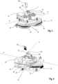
- FIG. 1 and 2 3 shows spatial representations from different viewing perspectives of a first embodiment of a floor cleaning device according to the invention, which is generally designated 10.
- This comprises a floor unit 12 and a guide part 14, which are connected to one another in an articulated manner via a joint arrangement 16.
- the base unit is assigned two brush-like tools 18, 20, which can be driven in rotation.
- the tool 18 is provided with a drive arrangement 22 and A drive arrangement 24 is assigned to the tool 20.
- the base unit 12 comprises a plate-like housing 26 to which the two drive arrangements 22, 24 are attached, with a free space being provided between them.
- the tools 18, 20 are mounted on the underside of the housing 26.
- a suction bar 28 is attached, on the underside of which a sealing lip arrangement 30 is provided, which is preferably made of rubber-like material. This can comprise a single or several sealing lips.
- a total of three support rollers 32 are provided on the rear of the suction bar 28, one of which is hidden in the illustrations.
- the floor unit 12 also has two transport rollers 34 on its front side, which are inclined upwards and are mounted in bearing projections 36. These transport rollers 34 serve to simplify handling of the floor cleaning device 10 according to the invention in a storage position, which will be explained in more detail below with reference to the Figures 14a to 14c is received.
- the guide part 14 has an elongated shaft 40, at the upper end of which an operating arrangement 42 is attached.
- This operating arrangement 42 comprises two handles 44, 46 with associated operating levers and a central control panel 48, on which a display and/or display fields are provided for showing the current operating state and operating parameters, such as the current charge level, the current speed of the tools 18, 20, fill levels for various liquids, such as clean water, dirty water, cleaning liquid, remaining operating time and similar information.
- the central control panel 48 also comprises setting instruments for switching on and controlling various operating parameters of the floor cleaning device 10, such as the speed of the tools 18, 20, or the like.
- a clean water container 50 with a filling nozzle 52 and a dirty water container 54 with a drain nozzle 56 are also provided on the shaft 40.
- the clean water container 50 can also be filled with a mixture of water and cleaning fluid.
- a separate container for cleaning fluid can be provided, which is not shown in the figures.
- Below the fluid containers 50, 54, in a separate housing area 58 in a manner not shown in detail, components for supplying clean water and cleaning fluid to the floor unit 12 and a suction unit, in particular with a suction turbine, for sucking in water applied to the floor and absorbing dirt with cleaning fluid are provided below the fluid containers 50, 54, in a separate housing area 58 in a manner not shown in detail.
- the inclination of the guide part 14 relative to the base unit 12 is explained below using the inclination of the guide part longitudinal axis F, which extends perpendicular to the first pivot axis A and runs through an effective line W which passes through the central axis of the two Handles 44, 46 are provided. Together with the first pivot axis A, the guide part longitudinal axis defines an inclination plane of the guide part 14 relative to the floor surface.
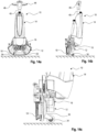
- the joint arrangement 16 which connects the base unit 12 to the guide part 14, will be described below with reference to Figures 3 and 4 described in more detail.
- this comprises a first bearing part 60 attached to the base unit, a joint element 62 coupled to it and a second bearing part 64 attached to the underside of the shaft 40 of the guide part 14.
- the joint element 62 comprises in its lower region for coupling to the first bearing part 60, which is attached to the base unit 12, a fork shape with two struts 68, 70, which are connected to one another at the rear via a reinforcing element 72.
- a bearing bolt 74 extends through the two struts 68, 70, which mounts the joint element 62 on the first bearing part 60 so that it can pivot about the pivot axis B.
- the joint element 62 comprises a bearing eye 76 formed in a conically tapered section that defines the first pivot axis A.
- the joint element 62 is connected to the second bearing part 64 at the lower end of the shaft 40 of the guide part 14 so that it can pivot about the first pivot axis A via this bearing eye 76 and an associated bearing bolt.
- the first bearing part 60 can be moved along a guide rail 80 on the base unit 12 and locked in any position along this guide rail 80. This is done via a clamping mechanism that can be released for moving and brought into a clamping position for fixing. Alternatively, it is possible to use predetermined locking positions in which the first bearing part can be fixed, for example, by inserting it into predetermined locking or latching openings. This adjustment option allows the mechanical point of engagement of the guide part on the floor unit to be changed and fixed as desired, which can influence the maneuvering properties of the floor cleaning device 10 according to the invention. This will be discussed in more detail below.
- the support device 90 comprises a base 94, with which it is mounted on the plate-shaped housing 26 of the base unit 12.
- the base 94 can also be moved along the rail 80 as desired.
- the base 94 has two lateral bearing jaws 96, 98, which extend upwards from the base 94.
- the locking bracket 92 already mentioned above is pivotably received in the bearing jaws 96, 98, with two free ends of the locking bracket 92 directed towards one another each serving as bearing bolt sections.
- the locking bracket 92 extends from the bearing jaws 96, 98 in a multiply angled or curved shape to an angled U-shaped area 100, this angled U-shaped area 100 being connected via two support sections 102 to the bracket sections 104 extending from there. It is understood that the locking bracket 92 can also be designed differently.
- a holding magnet 116 is provided in the base 94 between the two bearing jaws 96,98.
- a fixing element 120 which is provided for fixing to the joint element 62 and has a bearing opening 122 which can be brought into alignment with the bearing eye 76.
- the fixing element 120 is adapted to the geometry of the upper section of the joint element 62, has a plate-shaped design with stabilizing reinforcing ribs 124 and is at its in Figure 5 lower area is provided with receiving openings 126 into which the rounded ends 110 of the legs 108 can penetrate and be supported.
- Both the locking bracket 92 and the guide fork 106 are pivotable about a third pivot axis C relative to the base.
- the third pivot axis C runs essentially parallel to the second pivot axis B.
- Figure 7 shows the support device 90 in a state in which the locking bracket 92 is folded back and down so that the locking bracket 92 rests on the housing 26 of the base unit 12 in the space between the two drive arrangements 22, 24 in a passive position.
- the entire weight of the guide part 14 is supported on the base unit 12, solely through the action of the support device 90 with the receiving fork 106 and through the connection by the joint arrangement 16.
- An operator therefore no longer has to bear the weight of the guide part in whole or in part.
- the floor cleaning device 10 remains completely stable on its own without any support from the user - as long as the guide part 14 is not tilted sideways.
- the guide part 14 is pivoted sideways, the operator has to partially support the weight of the guide part.
- the base 94 can also be brought into different distances and relative positions relative to the joint arrangement 16 along the rail 80 and fixed there. This makes it possible for the receiving fork 106 to be brought into different pivot positions relative to the bearing jaws 96, 98 and thus also to support the guide part 14 in different angular positions relative to the floor unit 12. This also results in different orientations of the first pivot axis A with regard to its inclination relative to a floor surface.
- the support device is in the Figure 7 shown position allows the guide part to continue to pivot around the first pivot axis A without hindrance.
- the entire weight of the guide part 14 is diverted to the floor unit 12 via the support device 90 and the joint arrangement 16, so that the user does not have to hold the guide part 14 himself, in the embodiment shown not even partially, he can maneuver the floor cleaning device 10 to the left or to the right by actively pivoting the guide part about the pivot axis A with little effort, although he does have to partially hold the weight of the guide part 14 - depending on the degree of pivoting.
- the pivoting in combination with the support significantly improves the maneuvering properties, as will be explained below with reference to Figures 11a to 11c will be explained.
- the support device 90 has the additional function that it Figure 8 shown position, the floor cleaning device 10 can additionally lock against pivoting about the pivot axis A.
- Figure 8 shows the support device 90 in a state in which the locking bracket 92 is folded upwards so that the U-shaped area 100 is received in a housing recess 130 in the lower housing section 58 of the guide part 14.
- the essentially positive reception of the U-shaped area 100 of the locking bracket 92 in the housing recess 130 of the guide part 14 prevents the guide part 14 from being able to pivot about the pivot axis A.
- the locking bracket 92 which can be pivoted in its position, therefore creates a type of switchable locking function. This locking function enables the floor cleaning device 10 to be temporarily safely parked without the user having to hold or stabilize any components.
- the support device 90 shown can also be provided and used as a separate component for retrofitting purposes. It is thus possible to subsequently attach such a component to already known cleaning devices, all of which suffer from the problem that the operator has to take on and bear at least part of the weight of the guide part during operation when maneuvering, which is strenuous and tiring in the long run.
- a retrofittable support device can be used solely with the receiving fork 106 or a correspondingly designed device for absorbing the weight of the guide part 14 or additionally be provided with the pivotable locking bracket 92.
- Fig. 9 shows that the tool 20 is rotatable about a rotation axis R when the base unit 12 is viewed from the front, this rotation axis R being inclined inwards by an inclination angle ⁇ relative to a vertical S. Similarly, but mirrored about a central axis M, the tool 18 (in Figure 9 not shown) is inclined inwards.
- a propulsion effect in the direction of propulsion V is achieved.
- Fig. 10 shows by means of the arrows that the weight of the guide part 14 is introduced into the base unit 12 not only via the joint arrangement 16 but also equally via the support device 90 and there in particular via the receiving fork 106 as soon as the support device 90 is effective.
- the rear rollers 32 absorb somewhat more force and assume a somewhat greater supporting effect. This relieves some of the load on the brush-like tools 18, 20, which can extend their service life. If this effect of brush relief is not desired, one embodiment of the present invention can provide for the joint arrangement on the base unit to be arranged further forward in the direction of advance. The support device can then be arranged further back against the direction of advance. This makes it possible to achieve a more even or more central distribution of the weight of the guide unit on the base part.
- there are the advantages in terms of maneuvering and ease of use which are explained in more detail above and below.
- Figures 11a to 11c show various maneuvering conditions in which the support device 90 described above comes into play in a special way.
- Figure 11a shows in a side view of the floor cleaning device 10 according to the invention how the guide part 14 is pivoted backwards towards an operator (not shown) relative to the floor unit 12 by means of the joint arrangement 16 in such a way that the first pivot axis A runs at an angle ⁇ of approximately 30° relative to a surface to be cleaned.
- the support device 90 completely supports the weight force F GF of the guide part 14, so that an operator does not have to take on this weight force F GF .
- the operator can pivot the guide part 14 to the left and right for maneuvering with very little effort, gripping the handles 44 and 46 of the operating arrangement 42 and thereby operating the floor cleaning device 10.
- the operator must hold the weight of the guide part 14 proportionally.
- the guide part 14 of the floor cleaning device 10 can pivot to the left about the first pivot axis A, as shown by arrow P 1. This also shifts the center of gravity of the guide part 14 slightly to the left. As a result, the balance of forces shifts and a moment occurs in the floor unit 12 about the vertical axis of the floor unit, which is essentially perpendicular to the floor, also known as the yaw moment.
- the support device according to the invention offers the advantage that it absorbs the entire weight force F GF of the guide part 14 or at least a small or even a large part of it and transfers it to the floor unit 12.
- the operator is therefore already slightly or even significantly relieved of the load.
- the floor cleaning device 10 according to the invention is therefore much easier to operate and control, even during cleaning processes that take up a long time. By slightly tilting the floor cleaning device 10 backwards using the support device or by holding the floor cleaning device 10 against the direction of advance, the operator can have an additional influence on the advance effect.
- Figure 11c shows an analogous control movement by deflecting the guide part 14 according to arrow P 3 to the right, so that a corresponding curve follows according to arrow P 4 to the right.
- This type of control can be adjusted by selecting different angles of inclination ⁇ , i.e. with a large angle of inclination ⁇ , a relatively intensive curve movement with a small curve radius occurs, whereas with a small angle of inclination ⁇ , the curve movement is less intensive and has a larger curve radius.
- Other ways of influencing this movement are the intensity of the counter-holding by the operator and also the magnitude of the propulsion effect by the rotating tools 18, 20.
- the joint arrangement 16 can thus be moved forwards and backwards along the rail 80 on the floor unit 12, which changes the kinematics and maneuvering behavior of the floor cleaning device 10 according to the invention.
- the rule of thumb is that if the center of gravity of the guide part 50, on which the weight force F GF acts, is arranged in line with or only at a small horizontal distance (when viewed from above, i.e. in horizontal projection onto the floor surface) from the center of gravity of the floor unit 12, the floor cleaning device 10 according to the invention can be controlled more neutrally. On the other hand, if the distance is increased, the floor cleaning device 10 reacts more sensitively to deflection movements.
- the cleaning tools 18, 20 are relieved and no longer press so hard on the ground.
- This can influence the cleaning intensity, for example on sensitive surfaces.
- the wear on the tools 18, 20 can be reduced.
- the weight force F GF then places a greater load on the support rollers 32.
- the deflection movements correspond to Figures 11b and 11c can be completely blocked by the locking bracket 92, which facilitates permanent straight travel of the floor cleaning device 10.
- the locking bracket 92 can also be designed in such a way that it only allows small deflections with small angles ⁇ 1 and ⁇ 2.
- Fig. 12a and 12b show a maneuvering operating state in which an operator exerts a kind of pressure force F D on the handle 46 of the operating arrangement 42 from above on one side only and releases the other handle 44 or at most holds it in a guiding position, but not under a corresponding pressure force.
- This measure results in a slight tilting of the guide part 14 about the first pivot axis A and/or a slight counter-holding by the operator. Accordingly, unbalanced pressure conditions act through the support device 90 and the joint arrangement 16 in the base unit 12, which lead to a transverse force in the base unit 12.
- Fig. 13a and 13b show a maneuvering situation in which the operator controls the floor cleaning device 10 along a wall W (possibly under a projection), whereby he has swiveled the guide part 14 to the left in relation to the floor part 12 when viewed from behind, approximately to an angle of inclination ⁇ of approximately 70°.
- the floor unit 12 is also slightly inclined in order to make the best possible use of the brush surface of the tools 18, 20.
- the floor unit 12 is controlled along the wall W with a surface-protecting sliding surface 188, ie as indicated by the arrow Pw parallel to the wall. This is possible because the operating arrangement 42 is slightly turned by the operator (see arrow P B ) and a slight pressure force is exerted on the handle 44 from above (see force F D ).
- This maneuver with the aid of the support device 90, enables a favorable distribution of force in the floor unit 12 to be achieved on the opposing tools 18, 20.
- the floor cleaning device 10 can thus be easily maneuvered along the wall W parallel to it without little effort on the part of the operator.
- the floor cleaning device 10 can be rotated on the wall as desired, for example by 90 or 180°, without the need for any effort, almost effortlessly, without the guide part 14 coming into contact with the wall.
- Figures 14a to 14c show that the floor cleaning device 10 according to the invention can be brought into a space-saving and easily transportable storage or transport position.
- the floor unit 12 can be pivoted relative to the guide part 14 via the joint arrangement 16 and locked in this position in such a way that the bearing projections 36 are inclined forward and the transport rollers 34 are essentially in vertical alignment with the shaft 40 of the guide part 14.
- the handles 44, 46 By grasping the handles 44, 46, the floor cleaning device 10 can be easily moved on the transport rollers 34 without the tools 18, 20 coming into contact with the ground.
- the floor cleaning device can also be easily put down in this way, for example. If necessary, the floor unit 12 can be brought back into the operating position shown above.
- FIG. 15 shows a second embodiment of the invention.
- the support device 190 is designed as a compression spring 192, as schematically indicated. This has the effect that when the guide part 14 is pivoted about the second pivot axis B, at least part of the weight force F GF of the guide part 14 is absorbed by the spring. The greater the pivoting movement of the guide part 14, the stronger the supporting effect of the spring 192. This can also go to block to completely support the guide part 14. Furthermore or alternatively, a stop can be provided in order to pivot about a certain angle ⁇ of the first pivot axis A (see for example Fig. 11a ) to achieve complete support.
- the design of the support device 190 in the form of a compression spring 192 or an assembly with such a compression spring 192 is particularly simple and cost-effective.
- An alternative embodiment to this comprises a support device in the form of a single lever, which cannot be pivoted about a pivot axis running transversely to the direction of advance V, but can be folded away sideways about a pivot axis, wherein this pivot axis runs essentially in the direction of advance or at an acute angle to it.
- the support device can be designed to provide a storage surface for the guide part, on which the guide part can be pivoted about the first pivot axis A, but cannot be pivoted further about the second pivot axis B when there is contact between the guide part and the storage surface.
- this recess can accommodate the lever shape or also allow a relative pivoting movement of the guide part relative to the base unit about the first pivot axis.
- the support device can provide a positive and/or force-operated engagement or engagement of the support device on the guide part, so that any pivoting movement of the guide part relative to the base unit is temporarily prevented.
- the guide part cannot pivot about the first or second pivot axis when the support device engages the guide part.
- a recess or trough can be provided on the guide part or on the base unit, into which the support device engages in a positive or at least partially positive manner and thus ensures support while limiting the relative movement of the two components to one another.
- Another alternative embodiment which is not shown in detail in the drawing, comprises, for example, a joint arrangement between the base unit and the guide part, which is designed as a spring element, for example as a flexible rubber body or as a unit with metallic spring elements. It is possible to provide any pivoting direction with a spring effect.
- the support device is rigid, for example in the form of a rod. It is also possible to use a cable pull or a spring-loaded cable pull as a support device, for example in such a way that the cable pull is arranged in the direction of advance in front of the joint arrangement and thus blocks further pivoting about the second pivot axis B from a certain angular position of the guide part relative to the base unit, but allows pivoting of the guide part about the first pivot axis.
- a tension spring can also be provided, which can be locked on the base unit in the direction of advance in front of the joint arrangement.
- a support device 196 can be provided on the guide part 14, which supports the guide part 14 from a certain angle of the first pivot axis A relative to the floor or in a certain angular range directly on the floor.
- This can be, for example, a double-leg fork 198, which is pivotably mounted on the guide part 14 at its upper end via pins 200.
- Rollers 202 can be arranged on the fork 198 at its lower end, which roll on the floor in a supporting manner when the floor cleaning device 10 is in operation.
- the support device 196 can be moved between the Figure 16 with a solid line supporting operating position and a parking position shown with a dashed line.
- the support device 196 can be locked in the operating position and in the parking position and optionally also in intermediate positions, optionally with springs and/or damping.
- the operator In the operating position supporting the guide part 14, the operator is relieved by not having to hold the weight of the guide part 14 via the handles 44, 46, but can only grip the handles 44, 46 in order to maneuver the cleaning device 10 with light movements.
- a light counterhold on one of the handles 44, 46 ensures the effects described above for generating a torque in the base unit 12.
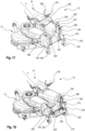
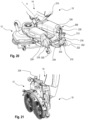
- FIG. 17 to 22 a further embodiment of the present invention is shown, in which a separate support module 208 with a pivotable support device 210 is provided on the base unit 12.
- the components of the base unit 12 and the guide part 14 already described above are not described again and are not provided with reference numerals again. The differences between this embodiment and the previous embodiments are discussed in particular.
- This pivotable support device 210 is provided on a base body 212 of the support module 208.
- the support module 208 can be attached in a modular manner to the floor unit 12 of an existing floor cleaning device 10 via a predetermined coupling interface.
- the support module 208 can be purchased as an additional component for retrofitting an existing floor cleaning device 10 and attached to it permanently or as required.
- the base body 212 is formed with a housing 214. This has at its Figures 17 and 18
- the rear area has two arms 216, 218, on which rollers 220, 222 are pivotably mounted on a vertical axis.
- the rollers 220, 222 serve to support the floor cleaning device 10 behind the suction bar. They align themselves automatically during the maneuvering of the floor cleaning device 10.
- Figures 22a , 20b and 22c show the support module 208 separately and detached from the floor cleaning device 10.
- the floor cleaning device can be detachably connected to this base body 212 via the specially designed interface.
- the support device 210 has two levers 224, 226 pivotably mounted on the base body 212 of the support module 208.
- the levers 224, 226 are pivotably mounted on the base body 212 via pivot pins 228, 230.
- at least one of the levers 224, 226 is spring-loaded into two predetermined positions via a tension spring 232, which will be described in more detail below.
- a support element 234 is attached to the two levers 224, 226. This can also be pivoted relative to the levers 224, 226 via pivot pins 230 and can be locked into the position shown in FIG. 1 via a latching hook 238. Figure 17 locked in the position shown.
- the support device 210 When comparing the Figures 17 and 18 that the support device 210 itself can move between a support position ( Figure 17 ) and a parking position ( Figure 18 ) can be pivoted.
- the articulation point 240 of the tension spring 232 on the housing 214 of the base body 212 relative to the pivot axis of the two levers 224, 226 determined by the pivot pins 228, 230, as in Figures 17 and 18
- the pivotable support device 210 is in both the support position ( Figure 17 ) and the parking position ( Figure 18 ) pre-tensioned.
- the tension spring 232 is initially tensioned, reaches a maximum tensioned state in the meantime and then relaxes again with further pivoting movement in the direction of the respective desired target position. The same applies to the opposite pivoting. This ensures that the support device 210 remains reliably and spring-loaded in the desired position.
- the support element 234 as shown in the Figures 19a and 19b is shown in individual part view, it can be seen that this has an arc-shaped base body 250, which at its in Figure 19a shown top comprises a largely closed surface 252 with an arcuate guide opening 254. On its underside (see Figure 19b ), the base body 250 is provided with a recess 256. A guide carriage 258 is guided in the guide opening 254, which can be moved within the guide opening 254 along an arcuate movement path predetermined by the latter and thereby slides on the surface 252 of the base body 250.
- the guide carriage 258 is secured to a trapezoidal counter body 260 via a screw connection 262 within the recess 256, the counter body 260 moving within the recess 256 with the guide carriage 258.
- Spring elements are provided on both sides of the trapezoidal counter body 260, in this case compression springs 264, 266, which preload the guide carriage 258 together with the counter body 260 into a central position within the guide opening 254 or the recess 256.
- the guide carriage 258 can be moved along an arcuate movement path within the opening 256 against the effect of this spring arrangement comprising the two pressure errors 264, 266.
- the guide carriage 258 has a metallic plate 268 on its upper side, which may be magnetic and can serve for temporary coupling with the guide part 14.
- FIG 17 one can see how the guide part 14 rests on the guide carriage 258.
- a positive engagement can also be provided, for example in such a way that a recess 270 (see Figures 17 and 18 ) is provided, which essentially holds the guide carriage 258 in a form-fitting manner.
- a supporting force connection can also be provided for this purpose via a magnet arrangement with the mediation of the metal plate 268.
- the guide part 14 is temporarily coupled to the guide carriage 258 in a detachable manner.
- the guide part 14 can be guided around the first pivot axis A and pivoted to the left and right via the guide carriage 258 on the support element 234, whereby this pivoting takes place against the resistance of the spring arrangement comprising the two springs 264, 266.
- the spring arrangement returns the guide part 14 to a central neutral position.
- the support device 210 acts as described above with respect to the other embodiments of the invention. It relieves the operator of the need to fully support the weight of the guide part 14 via the two handles 44, 46 and it also facilitates maneuvering in the manner described in detail above.
- the support element 234 can again assume two different positions, namely the position according to the illustration according to Figure 18 , in which the support element 234 with its surface 252 points downwards, and the position according to Figures 20 and 21 .
- the position according to Figure 18 has the advantage that the support element 234 is already in the correct alignment when it is pivoted upwards into the operating position for supporting the guide part 14.
- the support element 234 can be designed starting from the Figure 18 shown position additionally in the Figure 20 shown parking position, in which it is folded upwards relative to the levers 244, 226 to save space.
- the surface 252 then faces backwards as seen from the cleaning device 10. In this position, the support element 234 can be arranged to save space.
- This position according to Figure 20 is particularly suitable for moving the cleaning device 10 into its parking position according to Figure 21 as described above with reference to Figures 14a to 14c was described in detail.
- FIGs 22a to 22c The retrofittable separately designed support module 208 can be seen again separately in different views.
- the support device 210 is in its operating position accordingly Figure 17 shown for support
- Figure 22b the support device 210 is in the folded position accordingly Figure 18
- Figure 23c the support device 210 is shown in its parking position, wherein the support element 234 is also pivoted relative to the levers 224, 226.
- a support module 208 can be provided that can be retrofitted to a cleaning device 10 or attached to it as required.
- the support devices according to the present invention or the joint arrangement can additionally be designed with damper elements in order to dampen vibrations or to avoid an overly abrupt stop.
- dampers can be, for example, pneumatic or hydraulic dampers or simply be designed in the form of a damping rubber body.
- the invention has the advantage that by means of the support device in its different design according to the various embodiments, the weight force of the guide part 14 can be completely or at least partially introduced into the floor unit 12 in a variety of maneuvering situations and can be taken over by the latter, so that an operator can maneuver the floor cleaning device 10 according to the invention significantly better.
- the floor cleaning device 10 can be easily handled in various maneuvering situations by utilizing the propulsion effect of the tools 18, 20 that rotate in opposite directions and are slightly inclined relative to the floor surface. Tilting movements of the guide part 14 to the left, to the right, to the rear (towards the operator) and to the front (away from the operator) are easily possible as long as the support device does not engage. As soon as the support device engages in its various designs, advantageous maneuvering movements can be achieved by suitable force transmission (see above explanation) without great effort on the part of the operator.
Landscapes
- Engineering & Computer Science (AREA)
- General Engineering & Computer Science (AREA)
- Mechanical Engineering (AREA)
- Nozzles For Electric Vacuum Cleaners (AREA)
- Cleaning Implements For Floors, Carpets, Furniture, Walls, And The Like (AREA)
- Electric Vacuum Cleaner (AREA)
- Detergent Compositions (AREA)
- Gas Separation By Absorption (AREA)
- Electric Suction Cleaners (AREA)
Applications Claiming Priority (3)
| Application Number | Priority Date | Filing Date | Title |
|---|---|---|---|
| DE102020004413.1A DE102020004413A1 (de) | 2020-07-22 | 2020-07-22 | Bodenreinigungsvorrichtung, insbesondere Scheuer-Saug-Bodenreinigungsvorrichtung, mit verbesserten Manövriereigenschaften |
| EP21748862.6A EP4185178B1 (fr) | 2020-07-22 | 2021-07-22 | Dispositif de nettoyage de sols, en particulier dispositif de nettoyage de sols par frottement et aspiration, à propriétés de manoeuvre améliorées |
| PCT/EP2021/070567 WO2022018216A1 (fr) | 2020-07-22 | 2021-07-22 | Dispositif de nettoyage de sols, en particulier dispositif de nettoyage de sols par frottement et aspiration, à propriétés de manœuvre améliorées |
Related Parent Applications (1)
| Application Number | Title | Priority Date | Filing Date |
|---|---|---|---|
| EP21748862.6A Division EP4185178B1 (fr) | 2020-07-22 | 2021-07-22 | Dispositif de nettoyage de sols, en particulier dispositif de nettoyage de sols par frottement et aspiration, à propriétés de manoeuvre améliorées |
Publications (2)
| Publication Number | Publication Date |
|---|---|
| EP4445818A2 true EP4445818A2 (fr) | 2024-10-16 |
| EP4445818A3 EP4445818A3 (fr) | 2025-04-30 |
Family
ID=77155788
Family Applications (2)
| Application Number | Title | Priority Date | Filing Date |
|---|---|---|---|
| EP21748862.6A Active EP4185178B1 (fr) | 2020-07-22 | 2021-07-22 | Dispositif de nettoyage de sols, en particulier dispositif de nettoyage de sols par frottement et aspiration, à propriétés de manoeuvre améliorées |
| EP24196445.1A Pending EP4445818A3 (fr) | 2020-07-22 | 2021-07-22 | Dispositif de nettoyage de sol, en particulier dispositif de nettoyage de sol par aspiration et récure, présentant des propriétés de manoeuvre améliorées |
Family Applications Before (1)
| Application Number | Title | Priority Date | Filing Date |
|---|---|---|---|
| EP21748862.6A Active EP4185178B1 (fr) | 2020-07-22 | 2021-07-22 | Dispositif de nettoyage de sols, en particulier dispositif de nettoyage de sols par frottement et aspiration, à propriétés de manoeuvre améliorées |
Country Status (11)
| Country | Link |
|---|---|
| US (1) | US20230346188A1 (fr) |
| EP (2) | EP4185178B1 (fr) |
| JP (1) | JP2023534865A (fr) |
| KR (1) | KR20230048340A (fr) |
| CN (1) | CN116194024A (fr) |
| AU (1) | AU2021312329A1 (fr) |
| DE (1) | DE102020004413A1 (fr) |
| ES (1) | ES2991803T3 (fr) |
| HU (1) | HUE068616T2 (fr) |
| PL (1) | PL4185178T3 (fr) |
| WO (1) | WO2022018216A1 (fr) |
Families Citing this family (13)
| Publication number | Priority date | Publication date | Assignee | Title |
|---|---|---|---|---|
| DE102020004413A1 (de) | 2020-07-22 | 2022-01-27 | I-Mop Gmbh | Bodenreinigungsvorrichtung, insbesondere Scheuer-Saug-Bodenreinigungsvorrichtung, mit verbesserten Manövriereigenschaften |
| NL2026276B1 (en) * | 2020-08-17 | 2022-04-14 | Wensch Holding B V | Self-propelled cleaning device |
| ES3038264T3 (en) | 2021-03-26 | 2025-10-10 | Dextron Tech Ltd | Surface treatment tool |
| DE102021119016A1 (de) | 2021-07-22 | 2023-01-26 | I-Mop Gmbh | Bodenreinigungsvorrichtung |
| DE102022101563A1 (de) * | 2022-01-24 | 2023-07-27 | I-Mop Gmbh | Bodenbearbeitungsvorrichtung, bevorzugt eine Bodenreinigungsvorrichtung, wie beispielsweise eine Scheuer-Bodenreinigungsvorrichtung |
| WO2023174171A1 (fr) * | 2022-03-18 | 2023-09-21 | 深圳市普渡科技有限公司 | Laveur de sol |
| IT202200009203A1 (it) * | 2022-05-05 | 2023-11-05 | Lindhaus S R L | Snodo regolabile e bloccabile per macchine per la pulizia dei pavimenti |
| WO2025168842A2 (fr) * | 2024-02-09 | 2025-08-14 | I-Mop Gmbh | Appareil de nettoyage de surfaces, réservoir de fluide pour un appareil de nettoyage de surfaces, système de nettoyage de surfaces et procédé de nettoyage de surfaces |
| DE102024105791A1 (de) * | 2024-02-29 | 2025-09-04 | Alfred Kärcher SE & Co. KG | Bodenreinigungsmaschine mit Gebläseeinrichtung am Bodenkopf |
| WO2025216914A1 (fr) * | 2024-04-11 | 2025-10-16 | Diversey Europe B.V. | Machine de traitement de sols pour traitement de surface de plancher guidé à la main |
| WO2025219937A1 (fr) | 2024-04-18 | 2025-10-23 | Ruffo Gianmaria | Machine de nettoyage de sol améliorée |
| NL2037675B1 (en) * | 2024-05-13 | 2025-11-25 | Wensch Holding B V | Scrubber-drier |
| DE102024113488A1 (de) * | 2024-05-14 | 2025-11-20 | Hako Gmbh | Bodenreinigungsmaschine mit schwenkbarem Saugfuß |
Citations (7)
| Publication number | Priority date | Publication date | Assignee | Title |
|---|---|---|---|---|
| US2818312A (en) | 1955-03-10 | 1957-12-31 | Advance Machine Co | Selective handle connection for floor polishing machines |
| DE102009028944A1 (de) | 2009-08-27 | 2011-03-03 | Rudolf Franke | Handgeführtes Bodenbearbeitungsgerät |
| US20120246848A1 (en) | 2009-12-11 | 2012-10-04 | Hruby Jeffrey T | Orbital surface cleaning apparatus |
| US20130133146A1 (en) | 2010-07-27 | 2013-05-30 | Alfred Karcher Gmbh & Co. Kg | Floor treating apparatus |
| EP2832277B1 (fr) | 2013-08-02 | 2016-09-14 | i-mop GmbH | Appareil portatif de traitement des sols |
| DE102016208895A1 (de) | 2016-05-23 | 2017-11-23 | Rudolf Franke | Bodenbearbeitungsmodul sowie Bodenbearbeitungsmaschine mit einem solchen Bodenbearbeitungsmodul |
| DE102020004413A1 (de) | 2020-07-22 | 2022-01-27 | I-Mop Gmbh | Bodenreinigungsvorrichtung, insbesondere Scheuer-Saug-Bodenreinigungsvorrichtung, mit verbesserten Manövriereigenschaften |
Family Cites Families (35)
| Publication number | Priority date | Publication date | Assignee | Title |
|---|---|---|---|---|
| GB661388A (en) * | 1948-06-24 | 1951-11-21 | Karl Weger | Self-wringing mop |
| US3027581A (en) * | 1959-08-31 | 1962-04-03 | William E Holt | Floor machine with adjustable handle assembly |
| GB1239880A (en) * | 1969-08-27 | 1971-07-21 | J & L Seilaz A G | Improvements in or relating to a handle and swivel arrangement |
| CA1081281A (fr) * | 1978-02-28 | 1980-07-08 | Nicolas Boulachanis | Machine a fabriquer des lavettes |
| US4498214A (en) * | 1983-02-28 | 1985-02-12 | The Hoover Company | Carpet cleaning apparatus with auxiliary cleaning device arrangement |
| US4654918A (en) * | 1985-11-18 | 1987-04-07 | Jerald T. Allcock | Buffer deck assembly and surface maintenance apparatus |
| US4658459A (en) * | 1986-01-27 | 1987-04-21 | Advance Machine Company | Floor polishing machine |
| US5953781A (en) * | 1995-10-11 | 1999-09-21 | Nilfisk-Advance, Inc. | Adjustable handle assembly for floor maintenance machines |
| SE509783C2 (sv) * | 1997-07-29 | 1999-03-08 | Stig Olsson | Anordning vid städmaskin |
| JP4286984B2 (ja) * | 1999-07-29 | 2009-07-01 | クリーン工業株式会社 | 手押し型ローラー刷毛クリーナー |
| KR100774508B1 (ko) * | 2001-10-18 | 2007-11-08 | 엘지전자 주식회사 | 자립형 진공청소기 |
| US20030192573A1 (en) * | 2002-04-16 | 2003-10-16 | Loi Tran | Floor care machine with counter acting force |
| DE10334894B3 (de) * | 2003-07-29 | 2004-10-14 | Miele & Cie. Kg | Staubsauger mit einem durch einen Deckel verschließbaren Staubsammelraum |
| CN2643819Y (zh) * | 2003-09-24 | 2004-09-29 | 卢伟明 | 多角度平板刷 |
| US7665172B1 (en) * | 2004-03-19 | 2010-02-23 | Bissell Homecare, Inc. | Sweeper |
| US7530135B2 (en) * | 2004-12-30 | 2009-05-12 | Mark Benedict | Rotary carpet cleaning machine |
| DE102005032488A1 (de) * | 2005-07-04 | 2007-01-11 | Alfred Kärcher Gmbh & Co. Kg | Fahrbares Bodenreinigungsgerät |
| SE529373C2 (sv) * | 2006-05-05 | 2007-07-17 | Superclean Scandinavia Ab | Anordning vid städmaskin |
| GB2444898A (en) * | 2006-12-22 | 2008-06-25 | Dyson Technology Ltd | A vacuum cleaner nozzle |
| TW200925482A (en) * | 2007-12-06 | 2009-06-16 | Jarllytec Co Ltd | Supporting structure having connecting rod latching function |
| US8667643B2 (en) * | 2010-09-10 | 2014-03-11 | Euro-Pro Operating Llc | Method and apparatus for assisting pivot motion of a handle in a floor treatment device |
| US8162283B1 (en) * | 2010-10-28 | 2012-04-24 | Miraslav Royz | Stand for supporting a portable electronic device |
| KR101233027B1 (ko) * | 2010-11-15 | 2013-02-15 | 오세열 | 다기능 광택기 |
| US20140331445A1 (en) * | 2011-12-14 | 2014-11-13 | Euro-Pro Operating Llc | Surface cleaning apparatus with a sideways pivoting handle |
| TWM438098U (en) * | 2012-04-30 | 2012-09-21 | ming-xian Huang | Supporting apparatus |
| CN102688001B (zh) * | 2012-06-07 | 2015-02-04 | 苏州诚河清洁设备有限公司 | 地刷本体与手柄组件之间的锁定机构及清洁设备 |
| CN103939716A (zh) * | 2014-04-07 | 2014-07-23 | 卢景华 | 一种大屏手机及平板电脑的支撑架 |
| CN106163738B (zh) * | 2014-04-30 | 2019-03-08 | 胡斯华纳有限公司 | 研磨机或抛光机 |
| KR101692011B1 (ko) * | 2015-05-13 | 2017-01-03 | (주)씨에스전자 | 물걸레 청소기 |
| US9357891B1 (en) * | 2015-08-04 | 2016-06-07 | Richard C. Chappel | Cleaning apparatus holder |
| SE541067C2 (en) * | 2016-06-03 | 2019-03-26 | Husqvarna Ab | Floor grinding machine and method of setting a handle for a floor grinding machine |
| US10602902B2 (en) * | 2017-02-22 | 2020-03-31 | Bissell Homecare, Inc. | Motorized floor mop |
| DE102017107345A1 (de) * | 2017-04-05 | 2018-10-11 | Alfred Kärcher SE & Co. KG | Bodendüse für einen Dampfreiniger und Dampfreiniger |
| CN208222006U (zh) * | 2018-03-13 | 2018-12-11 | 广州市学伟电子产品有限公司 | 一种液晶电视专用支架 |
| CN208988745U (zh) * | 2018-08-14 | 2019-06-18 | 吴金辉 | 一种方便拆卸的家政服务用拖把 |
-
2020
- 2020-07-22 DE DE102020004413.1A patent/DE102020004413A1/de active Pending
-
2021
- 2021-07-22 KR KR1020237006151A patent/KR20230048340A/ko active Pending
- 2021-07-22 HU HUE21748862A patent/HUE068616T2/hu unknown
- 2021-07-22 ES ES21748862T patent/ES2991803T3/es active Active
- 2021-07-22 US US18/017,227 patent/US20230346188A1/en active Pending
- 2021-07-22 CN CN202180064840.2A patent/CN116194024A/zh active Pending
- 2021-07-22 EP EP21748862.6A patent/EP4185178B1/fr active Active
- 2021-07-22 JP JP2023504510A patent/JP2023534865A/ja active Pending
- 2021-07-22 AU AU2021312329A patent/AU2021312329A1/en active Pending
- 2021-07-22 PL PL21748862.6T patent/PL4185178T3/pl unknown
- 2021-07-22 WO PCT/EP2021/070567 patent/WO2022018216A1/fr not_active Ceased
- 2021-07-22 EP EP24196445.1A patent/EP4445818A3/fr active Pending
Patent Citations (10)
| Publication number | Priority date | Publication date | Assignee | Title |
|---|---|---|---|---|
| US2818312A (en) | 1955-03-10 | 1957-12-31 | Advance Machine Co | Selective handle connection for floor polishing machines |
| DE102009028944A1 (de) | 2009-08-27 | 2011-03-03 | Rudolf Franke | Handgeführtes Bodenbearbeitungsgerät |
| US20120246848A1 (en) | 2009-12-11 | 2012-10-04 | Hruby Jeffrey T | Orbital surface cleaning apparatus |
| US20130133146A1 (en) | 2010-07-27 | 2013-05-30 | Alfred Karcher Gmbh & Co. Kg | Floor treating apparatus |
| EP2832277B1 (fr) | 2013-08-02 | 2016-09-14 | i-mop GmbH | Appareil portatif de traitement des sols |
| DE202013012528U1 (de) | 2013-08-02 | 2017-04-20 | I-Mop Gmbh | Handgeführtes Bodenbearbeitungsgerät |
| EP3031378B1 (fr) | 2013-08-02 | 2017-06-28 | i-mop GmbH | Appareil portatif de traitement des sols |
| DE102016208895A1 (de) | 2016-05-23 | 2017-11-23 | Rudolf Franke | Bodenbearbeitungsmodul sowie Bodenbearbeitungsmaschine mit einem solchen Bodenbearbeitungsmodul |
| DE102020004413A1 (de) | 2020-07-22 | 2022-01-27 | I-Mop Gmbh | Bodenreinigungsvorrichtung, insbesondere Scheuer-Saug-Bodenreinigungsvorrichtung, mit verbesserten Manövriereigenschaften |
| EP4185178A1 (fr) | 2020-07-22 | 2023-05-31 | i-mop GmbH | Dispositif de nettoyage de sols, en particulier dispositif de nettoyage de sols par frottement et aspiration, à propriétés de manoeuvre améliorées |
Also Published As
| Publication number | Publication date |
|---|---|
| HUE068616T2 (hu) | 2025-01-28 |
| PL4185178T3 (pl) | 2025-01-13 |
| DE102020004413A1 (de) | 2022-01-27 |
| EP4185178A1 (fr) | 2023-05-31 |
| CN116194024A (zh) | 2023-05-30 |
| EP4185178C0 (fr) | 2024-08-28 |
| ES2991803T3 (es) | 2024-12-04 |
| AU2021312329A1 (en) | 2023-03-02 |
| JP2023534865A (ja) | 2023-08-14 |
| US20230346188A1 (en) | 2023-11-02 |
| EP4185178B1 (fr) | 2024-08-28 |
| KR20230048340A (ko) | 2023-04-11 |
| EP4445818A3 (fr) | 2025-04-30 |
| WO2022018216A1 (fr) | 2022-01-27 |
Similar Documents
| Publication | Publication Date | Title |
|---|---|---|
| EP4185178B1 (fr) | Dispositif de nettoyage de sols, en particulier dispositif de nettoyage de sols par frottement et aspiration, à propriétés de manoeuvre améliorées | |
| DE69402141T2 (de) | Schneefahrzeug | |
| DE3447401A1 (de) | Hammer mit schutzhaube | |
| EP4468927A1 (fr) | Appareil de traitement des sols avec partie de guidage équipée d'un agencement d'articulation | |
| WO2013064182A1 (fr) | Machine de nettoyage des sols guidée à la main | |
| WO2013064179A1 (fr) | Machine de nettoyage des sols guidée à la main | |
| EP4054393A1 (fr) | Machine de nettoyage de sol et procédé de fonctionnement d'une machine de nettoyage de sol | |
| DE102008045557B4 (de) | Transportanbau einer Vibrationsplatte | |
| EP1357782A1 (fr) | Machine roulante pour le travail du sol, en particulier tondeuse a gazon | |
| DE69913890T2 (de) | Handgeführte und handsteuerbare Strassenwalze | |
| WO2023002009A1 (fr) | Machine de nettoyage de sol | |
| EP1816265B1 (fr) | Balayeuse pour nettoyer des voies, des routes ou surfaces utilisables similaires | |
| DE10305611B4 (de) | Bodenreinigungsmaschine | |
| DE2619509C3 (de) | Mattenverlegevorrichtung zur großflächigen Sicherung des Hangendbereichs in Abbaubetrieben mit wanderndem Ausbau | |
| DE102006053076A1 (de) | Dunstabzugshaube | |
| DE8805617U1 (de) | Fußbodenreinigungsmaschine | |
| DE29814661U1 (de) | Handverfahrbares Gerät mit absenkbarem Werkzeug | |
| DE102024105830A1 (de) | Bodenreinigungsmaschine mit Sperreinrichtung | |
| DE2620920C3 (de) | Kippgehänge für von einem Transportmittel, insbesondere einer Einschienenhängebahn, mitgeführte Transportbehälter | |
| DE102023128404A1 (de) | Flurförderzeug umfassend ein rückhaltesystem | |
| EP4176977A1 (fr) | Outil de peintre articulé | |
| DE10308670A1 (de) | Reinigungsgerät | |
| EP0517193A2 (fr) | Dispositif pour le découpage de matériaux plats tels que du tissu, des feuilles ou similaires | |
| DE3428628A1 (de) | Wagen zum auftragen von fliessfaehigen substanzen | |
| DE2910378A1 (de) | Drehpflug |
Legal Events
| Date | Code | Title | Description |
|---|---|---|---|
| PUAI | Public reference made under article 153(3) epc to a published international application that has entered the european phase |
Free format text: ORIGINAL CODE: 0009012 |
|
| STAA | Information on the status of an ep patent application or granted ep patent |
Free format text: STATUS: REQUEST FOR EXAMINATION WAS MADE |
|
| 17P | Request for examination filed |
Effective date: 20240826 |
|
| AC | Divisional application: reference to earlier application |
Ref document number: 4185178 Country of ref document: EP Kind code of ref document: P |
|
| AK | Designated contracting states |
Kind code of ref document: A2 Designated state(s): AL AT BE BG CH CY CZ DE DK EE ES FI FR GB GR HR HU IE IS IT LI LT LU LV MC MK MT NL NO PL PT RO RS SE SI SK SM TR |
|
| TPAC | Observations filed by third parties |
Free format text: ORIGINAL CODE: EPIDOSNTIPA |
|
| REG | Reference to a national code |
Ref country code: DE Ref legal event code: R079 Free format text: PREVIOUS MAIN CLASS: A47L0011400000 Ipc: A47L0011300000 |
|
| PUAL | Search report despatched |
Free format text: ORIGINAL CODE: 0009013 |
|
| AK | Designated contracting states |
Kind code of ref document: A3 Designated state(s): AL AT BE BG CH CY CZ DE DK EE ES FI FR GB GR HR HU IE IS IT LI LT LU LV MC MK MT NL NO PL PT RO RS SE SI SK SM TR |
|
| RIC1 | Information provided on ipc code assigned before grant |
Ipc: A47L 11/40 20060101ALI20250325BHEP Ipc: A47L 11/30 20060101AFI20250325BHEP |