EP0517193A2 - Dispositif pour le découpage de matériaux plats tels que du tissu, des feuilles ou similaires - Google Patents
Dispositif pour le découpage de matériaux plats tels que du tissu, des feuilles ou similaires Download PDFInfo
- Publication number
- EP0517193A2 EP0517193A2 EP92109396A EP92109396A EP0517193A2 EP 0517193 A2 EP0517193 A2 EP 0517193A2 EP 92109396 A EP92109396 A EP 92109396A EP 92109396 A EP92109396 A EP 92109396A EP 0517193 A2 EP0517193 A2 EP 0517193A2
- Authority
- EP
- European Patent Office
- Prior art keywords
- boom
- arm
- cutting device
- carriage
- cantilever
- Prior art date
- Legal status (The legal status is an assumption and is not a legal conclusion. Google has not performed a legal analysis and makes no representation as to the accuracy of the status listed.)
- Withdrawn
Links
Images


Classifications
-
- B—PERFORMING OPERATIONS; TRANSPORTING
- B26—HAND CUTTING TOOLS; CUTTING; SEVERING
- B26D—CUTTING; DETAILS COMMON TO MACHINES FOR PERFORATING, PUNCHING, CUTTING-OUT, STAMPING-OUT OR SEVERING
- B26D7/00—Details of apparatus for cutting, cutting-out, stamping-out, punching, perforating, or severing by means other than cutting
- B26D7/26—Means for mounting or adjusting the cutting member; Means for adjusting the stroke of the cutting member
- B26D7/2628—Means for adjusting the position of the cutting member
-
- B—PERFORMING OPERATIONS; TRANSPORTING
- B26—HAND CUTTING TOOLS; CUTTING; SEVERING
- B26F—PERFORATING; PUNCHING; CUTTING-OUT; STAMPING-OUT; SEVERING BY MEANS OTHER THAN CUTTING
- B26F1/00—Perforating; Punching; Cutting-out; Stamping-out; Apparatus therefor
- B26F1/38—Cutting-out; Stamping-out
- B26F1/3806—Cutting-out; Stamping-out wherein relative movements of tool head and work during cutting have a component tangential to the work surface
- B26F1/3813—Cutting-out; Stamping-out wherein relative movements of tool head and work during cutting have a component tangential to the work surface wherein the tool head is moved in a plane parallel to the work in a coordinate system fixed with respect to the work
Definitions
- the invention relates to a cutting device according to the preamble of claim 1.
- a cutting device of this type is used to cut a layer of fabric placed on the table according to a pattern using the cutting machine.
- the cutting machine is manually shifted on the table in accordance with the cutting lines of the cutting pattern, being held at the free end of the boom, which due to the movability of the carriage and the pivotability of the boom relative to the carriage is able to follow the movement of the cutting machine predetermined by the cutting pattern .
- the necessary shifting and pivoting forces are to be applied by the operator's hand.
- the boom is a so-called articulated boom, consisting of a rear boom arm which is pivotally mounted on the carriage about a vertical axis and a front boom arm which is connected to the latter by a joint with a vertical articulated axis and which supports the cutting machine at its free end.
- an angle measuring device with associated limit switches and actuating switching cams as well as a switching device are provided which, when an angle is exceeded, follows the carriage so that the angle remains within a certain angular range.
- the invention has for its object to reduce the construction and control effort in a cutting device of the type mentioned and still ensure good travel of the carriage along the table.
- the solution according to the invention is based on the idea of eliminating the motor drive for the car and manually moving the car. This is not possible for several reasons in the known configuration and also in the case of conventional roughing methods.
- the known designs are of heavy construction and they also have fairly stiff guides for the car. A stiffness predetermined thereby is made even more difficult by the weight of the drive.
- a possible attempt by the operator to go to the back of the table and to try to move the carriage by pulling on the arm extending parallel to the back of the table is not possible in the known designs due to the existing drive and due to the sluggishness .
- the carriage is freely and easily displaceably supported by hand, which is preferably achieved with roller bearings such as a ball guide and / or a roller guide.
- the boom can be limited in its lateral pivoting movement in a position in which the operator can exert an effective longitudinal force on the table, which due to the movement limitation of the boom acts without significant losses due to transverse components in the longitudinal direction on the carriage and this shifts due to its smoothness. The operator can do this from the front of the table and also from the other sides of the table.
- the movement limiting device it is the purpose of the movement limiting device to hold the boom in such a position that it is able to transmit the traction or pushing force exerted on it in the longitudinal direction of the table to the carriage.
- the limiting device between the carriage and the rear or front extension arm can be effective.
- the limiting device can only be effective in one longitudinal direction of the table or in both longitudinal directions.
- it can be formed by a stop for the boom.
- An advantageous embodiment for the second case is a clutch or brake, which is also a rigid of the boom or its parts movable relative to each other.
- the subclaims contain features that contribute to problem solving and also enlarge the effective range of the boom, facilitate its handling, improve stability and function, and also enable simple and inexpensive production.
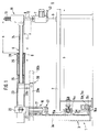
- the main parts of the cutting device 1 are a table 2, a carriage 3 which can be displaced horizontally at the rear of the table 2 and which has a vertical support column 3a, an arm-shaped, horizontal one which is mounted on the support column 3 and can be pivoted about a vertical pivot axis 4 (B) from the back of the table 2 to the front operating side 5 extending arm 6 and a cutting machine arranged at the front end of the arm 6 in the form of a butt knife machine 7, which stands with its support leg 8 on the table 2 and about a vertical axis of rotation 9 in a Boom 6 attached pivot bearing 11 is rotatably mounted.
- the butt knife machine 7 is preferably also vertically displaceable C in the pivot bearing 11 and thus adjustable in height and preferably lockable in the respective altitude.
- a round rod 12 projecting upwards from the butt knife machine can be used, which passes through and projects above the rotary bearing 11, a compression spring 13 preferably being arranged on the projecting part of the rod 12 and between an end-side abutment, e.g. in the form of a disc, and the pivot bearing 11 can be clamped for the purpose of weight compensation for the butt knife machine 7.
- the carriage 3 is guided on two horizontal guide rails 14a, 14b, which are fastened to the rear of the table 2, so that they can be moved horizontally by means of rollers.
- the upper guide rail 14a is a rod with a round cross section, which is connected with radial threaded bolts and can therefore be adjusted horizontally on the frame of the table 2 by means of nuts, and on which the carriage 3 by means of a ball guide bush 15a and a bearing 15b which engages around it and is attached to the carriage is slidably guided.
- the lower guide rail 14b is a square tube with an integrally formed, preferably vertical leg 14c, which is encompassed on both sides by rollers 15c which are freely rotatably mounted on a horizontal guide arm 15d fastened to the carriage 3.
- a pivot bearing 16 containing the vertical pivot axis 4 is formed at the upper end of the support column 3a. It has a bearing part 17, preferably screwed to the front of the support column 3a formed from a rectangular or square tube, with a vertical bearing bore, in which a vertical pivot pin 19 of a clamping head 21 arranged at its upper end is horizontally rotatably mounted.
- the clamping head 21 has a horizontal through-hole with a cross-sectional shape and size corresponding to the cross-sectional shape and size of the arm 6 and is provided in the sense of a clamp with a clamp bracket 22 which overlaps the arm 6 and is screwed.
- the cantilever 6 is formed by a telescopic rod with a rear cantilever arm 23 held on the support column 3 and a front cantilever arm 24, whose cross-sectional area is smaller than the cross-sectional area of the rear cantilever arm 23, protrudes coaxially into the front end of the rear cantilever arm 23 and through in the longitudinal direction of the boom 6 one behind the other and between the rear and front boom arms 23, 24 arranged ball guides 25, 26 are guided together in their longitudinal direction. Anti-rotation devices (not shown) are integrated in the ball guides 25, 26.
- the cantilever arms 23, 24 consist of metal tubes, in particular aluminum tubes, of round or square cross-section.
- the displacement dimension a of the front cantilever arm 24 is approximately half the table width b.
- the rear cantilever arm 23 is horizontally displaceable and lockable in the clamping head 21 and can thus be adapted to different table widths b.
- the degree of freedom created by the telescopability is denoted by D.
- the butt knife machine 7 can be supported on the boom 6 due to its displaceability with the trolley 3 parallel to the operating side 5, its horizontal pivotability in the pivot bearing 16 and its telescopic capability on the whole Table surface to be moved.
- the swiveling in the swivel bearing 16 and the telescoping can each be optionally canceled.
- clutches or brakes 27, 28 are used, one of which is effective between the cantilever arms 23, 24 and is preferably arranged at the front end of the rear cantilever arm 23 and the other is assigned to the pivot bearing 16 and is formed from two clutch or brake parts arranged one above the other , of which the upper part is connected to the pivot pin 19 and the lower part is fastened to the support column 3a by means of a bracket.
- a switch is provided on the cutting machine 7 near the handle 43.
- the boom 6 is assigned a swivel limiting device 20 that limits its horizontal swiveling capacity and is effective between the carriage 3 or an attachment part of the same and the rear boom arm 23.
- the limiting device 20 has two support arms 20a fastened on both sides of the carriage 3, which project forward from the carriage 3 and thereby extend obliquely outwards.
- stop pieces 20b are attached, which project upwards into the pivoting plane of the extension arm 23 and limit its pivoting movement to the outside.
- the stop pieces 20b enclose an angle w (FIG. 2) which limits the pivoting movement B of the arm 6 and which is 0 to approximately 100 °, preferably approximately 45 °.
- the stop pieces 20b are preferably adjustable, in particular pivotally mounted, after releasing a locking device from the pivoting plane of the extension arm 23 into a release position. In this release position, the limiting device 20 is out of operation.
- Fig. 3 shows in vertical cross section an embodiment of a telescopic configuration for the boom 6, the boom arms 23, 24 being formed by square tubes.
- rollers 29 are provided for the longitudinal displacement of the front boom arm 24 in the rear boom arm 23, the rollers 29 preferably being arranged between the vertical walls 31, 32 of the boom arms 23, 24.
- Two horizontal guide strips 33, 34 are arranged on both vertical walls 32 of the front extension arm 24 and are spaced from the walls 32 by intermediate pieces 35. The attachment is carried out by screws 36 which pass through the guide strips 33, 34 and the intermediate pieces 35 in through holes and the walls 32 in threaded holes.
- the guide strips 33, 34 are located approximately centrally between the walls 31, 32, the distance between them being so large that the rollers 29 have space therein.
- Both guide strips 33, 34 are upright flat strips, one of the guide strips 33 having a rectangular cross-sectional shape, while the narrow sides of the other guide strip 34 are roof-shaped.
- the rollers 29 are arranged above and below the guide rails 33, 34 and are freely rotatably supported on bearing axles 37, 38, which are arranged above and below the guide rails 33, 34, and which pass through the walls 31 in holes with threaded pins and are screwed from the outside with nuts .
- the rollers 29a interacting with the guide strip 34 having a rectangular cross-sectional shape have a cylindrical shape and can be formed by roller bearings which are placed on the associated bearing axes 37.
- the rollers 29b assigned to the other guide strip 34 have a circumferential groove 38 which is adapted to the roof shape of this guide strip 34 in its cross-sectional shape and into which the guide strip 34 is received with little running play.
- the rollers 29b are formed by two ball bearings arranged next to one another and a running sleeve 41 seated thereon, in which the circumferential groove 38 is incorporated.
- rollers 29a To be able to absorb lateral forces, two identical ball bearings are preferably provided, each of which can absorb axial forces on one side, the ball bearings being arranged opposite one another, so that the pair of ball bearings can absorb axial forces in both directions.
- the associated guide strips 33, 34 are provided between them.
- the vertical distance between the holes 42 covered by the bearing axles 37, 38 is dimensioned so large that the guide strips 33, 34 fit between the pairs of rollers with little running play.
- a particularly pneumatic cylinder-piston drive can also be provided, which is integrated in the pivot bearing 11 and with which the butt knife machine 7 can be adjusted and preferably locked in optional height settings.
- the boom 6 is a so-called articulated boom, i.e. the rear and front cantilever arms 23, 24 are connected to one another by a joint 45 with a vertical joint axis 46 which can be pivoted horizontally (E).
- the articulated arm buckles to one side or the other, with the exception of the dead center, in which the outrigger arms 23, 24 are aligned with one another.
- the joint 45 is arranged on a slide 47 which is guided in or on a longitudinal guide 48 formed on the rear extension arm 23 in the longitudinal direction of the rear extension arm 23 so as to be freely displaceable. Because of this configuration, this boom 6 also has the further degree of freedom (D), which also enables the butt knife machine 7 to be adjusted when the cantilever arms 23, 24 are stretched or enclose a very acute angle. When the adjustment is then made, the extension arms are pushed together or pulled apart. In an approximately right-angled position of the cantilever arms 23, 24, the cantilever arms 23, 24 will rotate relative to one another before a displacement takes place in the longitudinal guide 48. The respective movement (turning / pushing) occurs automatically depending on the forces that occur.
- D further degree of freedom
- a guide rod or a guide profile can be arranged or formed on the rear cantilever arm 23, on or in which the slide 47 of the corresponding profile is received. It is possible within the scope of the invention to assign a clutch or brake to the pivot bearing 16 and also to the sliding bearing generally designated 49, which can be switched on and off from the operating side 5, also in the embodiment according to FIG. It is also possible to arrange a corresponding sliding pivot bearing 49 on the front extension arm 24 instead of on the rear extension arm 23, so that the effective length of the front extension arm 24 can be varied.
- the boom is telescopic in its longitudinal direction. This gives him an additional possibility of axial movement, which greatly facilitates the guidance of the cutting machine.
- the boom has a greater functional length, and therefore the table surface and the corner areas of the table can be better used with easy guidance.
- the cutting machine can also be easily shifted due to the telescopability if the boom arms enclose an angle of approximately or 180 ° or the direction of displacement is directed at an acute angle to the boom arms.
- the boom is telescoped, ie pulled apart or pushed together. This requires only relatively small adjustment forces because the stiff buckling movement of the cantilever arms is eliminated at least when pushing. With the configurations according to the invention, the cutting machine can therefore be more easily guided according to predetermined cutting pattern lines.
- the limiting device 20 allows both the telescopic boom (Fig. 1) and the articulated boom (Fig. 4) to be rigid by a pivoting limitation of the rear boom arm 23 in such a position that the operator can pull the front boom arm 24 from the operator side or thrust in the longitudinal direction of the table 2 are transferred to the trolley 3 without significant losses due to transverse forces.
- the operator can pivot the rear cantilever arm 24 so far that it strikes the stop piece 20b and pull or push in the same lateral direction on the front cantilever arm 24.
- Rigidness of the front boom arm 24 by engaging the brake 28 (telescopic boom) or a corresponding brake in the swivel joint 45 and / or in the sliding joint 49 (articulated arm) can be helpful here.
- Rigidness can also be achieved by switching on the brake 27, with the simultaneous switching on of the brake 28 or a corresponding brake in the rotary and / or sliding joint 45, 49 also being helpful here.
- This configuration enables a rigidity in each boom position or boom arm position, e.g. even at 0 °.
- an energy accumulator 51 is arranged, as shown in FIGS. 5 and 6.
- Such can be formed by an elastic member such as a tension or compression spring.
- compression springs 52 are provided, which are held on one of the two stop parts, here on the stop piece 20b, and extend in the direction of the extension arm 24.
- the length of the springs 52 can be, for example, only a few centimeters or about half the lateral swivel path.
- tension springs 53 are provided which are held on the extension arm 24 and on the associated stop piece 20b and thus center the extension arm 24 in the center.
- the maximum spring force in the stop position can be less or slightly greater than the longitudinal force required to move the carriage 3.
- the energy accumulators prevent shocks and create balanced kinematics. It is also advantageous to provide the front boom arm 24 of the telescopic boom 6 with end position damping, e.g. assign using springs.
Landscapes
- Life Sciences & Earth Sciences (AREA)
- Forests & Forestry (AREA)
- Engineering & Computer Science (AREA)
- Mechanical Engineering (AREA)
- Treatment Of Fiber Materials (AREA)
- Details Of Cutting Devices (AREA)
Applications Claiming Priority (2)
| Application Number | Priority Date | Filing Date | Title |
|---|---|---|---|
| DE19914118322 DE4118322A1 (de) | 1991-06-04 | 1991-06-04 | Zuschneidevorrichtung fuer flachmaterial wie stoffe, folien oder dergleichen |
| DE4118322 | 1991-06-04 |
Publications (2)
| Publication Number | Publication Date |
|---|---|
| EP0517193A2 true EP0517193A2 (fr) | 1992-12-09 |
| EP0517193A3 EP0517193A3 (en) | 1993-02-03 |
Family
ID=6433166
Family Applications (1)
| Application Number | Title | Priority Date | Filing Date |
|---|---|---|---|
| EP19920109396 Withdrawn EP0517193A3 (en) | 1991-06-04 | 1992-06-03 | Apparatus for cutting out flat materials such as fabric, sheets or the like |
Country Status (3)
| Country | Link |
|---|---|
| EP (1) | EP0517193A3 (fr) |
| JP (1) | JPH08155890A (fr) |
| DE (1) | DE4118322A1 (fr) |
Cited By (2)
| Publication number | Priority date | Publication date | Assignee | Title |
|---|---|---|---|---|
| CN110422157A (zh) * | 2019-08-18 | 2019-11-08 | 青岛理工大学 | 制动软管总成加工中心 |
| CN115570625A (zh) * | 2022-09-11 | 2023-01-06 | 云南锦鼎光电科技有限公司 | 一种偏光片生产加工用剪裁装置及方法 |
Family Cites Families (6)
| Publication number | Priority date | Publication date | Assignee | Title |
|---|---|---|---|---|
| US2998651A (en) * | 1955-08-30 | 1961-09-05 | Emil Hoogland Fa | Cutting machine for cutting textile or other material |
| US3935950A (en) * | 1973-09-04 | 1976-02-03 | Quality Steel Fabricators, Inc. | Industrial robot |
| US4092777A (en) * | 1976-03-16 | 1978-06-06 | Krauss U. Reichert Gmbh & Co. Kg Spezialmaschinenfabrik | Cutting-out machine for flat material |
| DE3132127C2 (de) * | 1981-08-14 | 1984-10-18 | Krauss U. Reichert Gmbh + Co Kg Spezialmaschinenfabrik, 7012 Fellbach | Zuschneidevorrichtung für Flachmaterial wie Stoffe, Folien und dergleichen |
| US4554738A (en) * | 1983-09-15 | 1985-11-26 | Eastman Machine Company | Apparatus for supporting and guiding machine for operating on sheet material such as cloth |
| JPH07121513B2 (ja) * | 1986-10-17 | 1995-12-25 | フアナツク株式会社 | 産業用ロボツトの旋回胴旋回域設定装置 |
-
1991
- 1991-06-04 DE DE19914118322 patent/DE4118322A1/de active Granted
-
1992
- 1992-06-03 JP JP16851492A patent/JPH08155890A/ja active Pending
- 1992-06-03 EP EP19920109396 patent/EP0517193A3/de not_active Withdrawn
Cited By (3)
| Publication number | Priority date | Publication date | Assignee | Title |
|---|---|---|---|---|
| CN110422157A (zh) * | 2019-08-18 | 2019-11-08 | 青岛理工大学 | 制动软管总成加工中心 |
| CN110422157B (zh) * | 2019-08-18 | 2024-02-20 | 青岛理工大学 | 制动软管总成加工中心 |
| CN115570625A (zh) * | 2022-09-11 | 2023-01-06 | 云南锦鼎光电科技有限公司 | 一种偏光片生产加工用剪裁装置及方法 |
Also Published As
| Publication number | Publication date |
|---|---|
| EP0517193A3 (en) | 1993-02-03 |
| DE4118322A1 (de) | 1992-12-10 |
| DE4118322C2 (fr) | 1993-06-03 |
| JPH08155890A (ja) | 1996-06-18 |
Similar Documents
| Publication | Publication Date | Title |
|---|---|---|
| DE19631042C5 (de) | Straßenbaumaschinen zum Bearbeiten von Fahrbahnen | |
| DE3521047C1 (de) | Mikroskop | |
| DE2915288C2 (de) | Kaltkreissäge mit einem schwenkbaren Sägeblattarm | |
| EP0595074A1 (fr) | Dispositif de serrage | |
| DE2258806A1 (de) | Stuetzausleger | |
| DD153404A5 (de) | Gleisstopfmaschine | |
| DE2540403C3 (de) | Schmiedemaschine mit zwei gegeneinander wirkenden Werkzeugträgern | |
| DE2754009A1 (de) | Fahrzeug zum transportieren von lasten | |
| WO1998043856A2 (fr) | Appareil de levage pour vehicules a moteur et attelages de vehicules, en particulier cric | |
| DE3420005A1 (de) | Gabelzinkenverstellgeraet fuer einen gabelstapler | |
| DE1458633C3 (de) | Polar verstellbare, kraftbetätigte Anstellvorrichtung für Gesteinsbohrmaschinen | |
| DE4118322C2 (fr) | ||
| DE3207177C2 (de) | Tisch mit einer in der Höhe und in der Neigung verstellbaren Tischplatte | |
| DE2540644C3 (de) | Längenveränderbare Stange, insbesondere Erdungsstange oder Betätigungsstange für elektrotechnische Einrichtungen | |
| DE3442940A1 (de) | Hebetisch | |
| DE3037741C2 (de) | Antriebsvorrichtung für einen Schlitten | |
| DE4118320C2 (fr) | ||
| DE3932955C1 (en) | Coating device for silk-screen printing - incorporates guide and tipping device for ink trough | |
| DE4118321C2 (fr) | ||
| DE3008626A1 (de) | Wagenheber | |
| DE3412755A1 (de) | Ausfahrbares fahrwerk fuer einen standkoerper | |
| DE2921834C2 (de) | Arretiervorrichtung | |
| DE3007668C2 (de) | Krankentragenbühne | |
| DE602006000299T2 (de) | Schneidtisch für Metallbleche | |
| DE102004059322B4 (de) | Vorrichtung zum Bewegen von wenigstens zwei Greifvorrichtungen |
Legal Events
| Date | Code | Title | Description |
|---|---|---|---|
| PUAI | Public reference made under article 153(3) epc to a published international application that has entered the european phase |
Free format text: ORIGINAL CODE: 0009012 |
|
| AK | Designated contracting states |
Kind code of ref document: A2 Designated state(s): DE ES FR GB IT |
|
| PUAL | Search report despatched |
Free format text: ORIGINAL CODE: 0009013 |
|
| AK | Designated contracting states |
Kind code of ref document: A3 Designated state(s): DE ES FR GB IT |
|
| 17P | Request for examination filed |
Effective date: 19930323 |
|
| 17Q | First examination report despatched |
Effective date: 19941128 |
|
| STAA | Information on the status of an ep patent application or granted ep patent |
Free format text: STATUS: THE APPLICATION IS DEEMED TO BE WITHDRAWN |
|
| 18D | Application deemed to be withdrawn |
Effective date: 19950715 |