EP4446182A2 - Système de freinage à décompression partiellement simultanée en système ouvert et fermé - Google Patents
Système de freinage à décompression partiellement simultanée en système ouvert et fermé Download PDFInfo
- Publication number
- EP4446182A2 EP4446182A2 EP24194897.5A EP24194897A EP4446182A2 EP 4446182 A2 EP4446182 A2 EP 4446182A2 EP 24194897 A EP24194897 A EP 24194897A EP 4446182 A2 EP4446182 A2 EP 4446182A2
- Authority
- EP
- European Patent Office
- Prior art keywords
- pressure
- piston
- brake
- wheel
- valve
- Prior art date
- Legal status (The legal status is an assumption and is not a legal conclusion. Google has not performed a legal analysis and makes no representation as to the accuracy of the status listed.)
- Granted
Links
Images






Classifications
-
- B—PERFORMING OPERATIONS; TRANSPORTING
- B60—VEHICLES IN GENERAL
- B60T—VEHICLE BRAKE CONTROL SYSTEMS OR PARTS THEREOF; BRAKE CONTROL SYSTEMS OR PARTS THEREOF, IN GENERAL; ARRANGEMENT OF BRAKING ELEMENTS ON VEHICLES IN GENERAL; PORTABLE DEVICES FOR PREVENTING UNWANTED MOVEMENT OF VEHICLES; VEHICLE MODIFICATIONS TO FACILITATE COOLING OF BRAKES
- B60T13/00—Transmitting braking action from initiating means to ultimate brake actuator with power assistance or drive; Brake systems incorporating such transmitting means, e.g. air-pressure brake systems
- B60T13/10—Transmitting braking action from initiating means to ultimate brake actuator with power assistance or drive; Brake systems incorporating such transmitting means, e.g. air-pressure brake systems with fluid assistance, drive, or release
- B60T13/66—Electrical control in fluid-pressure brake systems
- B60T13/68—Electrical control in fluid-pressure brake systems by electrically-controlled valves
- B60T13/686—Electrical control in fluid-pressure brake systems by electrically-controlled valves in hydraulic systems or parts thereof
-
- B—PERFORMING OPERATIONS; TRANSPORTING
- B60—VEHICLES IN GENERAL
- B60T—VEHICLE BRAKE CONTROL SYSTEMS OR PARTS THEREOF; BRAKE CONTROL SYSTEMS OR PARTS THEREOF, IN GENERAL; ARRANGEMENT OF BRAKING ELEMENTS ON VEHICLES IN GENERAL; PORTABLE DEVICES FOR PREVENTING UNWANTED MOVEMENT OF VEHICLES; VEHICLE MODIFICATIONS TO FACILITATE COOLING OF BRAKES
- B60T13/00—Transmitting braking action from initiating means to ultimate brake actuator with power assistance or drive; Brake systems incorporating such transmitting means, e.g. air-pressure brake systems
- B60T13/74—Transmitting braking action from initiating means to ultimate brake actuator with power assistance or drive; Brake systems incorporating such transmitting means, e.g. air-pressure brake systems with electrical assistance or drive
- B60T13/741—Transmitting braking action from initiating means to ultimate brake actuator with power assistance or drive; Brake systems incorporating such transmitting means, e.g. air-pressure brake systems with electrical assistance or drive acting on an ultimate actuator
-
- B—PERFORMING OPERATIONS; TRANSPORTING
- B60—VEHICLES IN GENERAL
- B60T—VEHICLE BRAKE CONTROL SYSTEMS OR PARTS THEREOF; BRAKE CONTROL SYSTEMS OR PARTS THEREOF, IN GENERAL; ARRANGEMENT OF BRAKING ELEMENTS ON VEHICLES IN GENERAL; PORTABLE DEVICES FOR PREVENTING UNWANTED MOVEMENT OF VEHICLES; VEHICLE MODIFICATIONS TO FACILITATE COOLING OF BRAKES
- B60T13/00—Transmitting braking action from initiating means to ultimate brake actuator with power assistance or drive; Brake systems incorporating such transmitting means, e.g. air-pressure brake systems
- B60T13/74—Transmitting braking action from initiating means to ultimate brake actuator with power assistance or drive; Brake systems incorporating such transmitting means, e.g. air-pressure brake systems with electrical assistance or drive
- B60T13/745—Transmitting braking action from initiating means to ultimate brake actuator with power assistance or drive; Brake systems incorporating such transmitting means, e.g. air-pressure brake systems with electrical assistance or drive acting on a hydraulic system, e.g. a master cylinder
-
- B—PERFORMING OPERATIONS; TRANSPORTING
- B60—VEHICLES IN GENERAL
- B60T—VEHICLE BRAKE CONTROL SYSTEMS OR PARTS THEREOF; BRAKE CONTROL SYSTEMS OR PARTS THEREOF, IN GENERAL; ARRANGEMENT OF BRAKING ELEMENTS ON VEHICLES IN GENERAL; PORTABLE DEVICES FOR PREVENTING UNWANTED MOVEMENT OF VEHICLES; VEHICLE MODIFICATIONS TO FACILITATE COOLING OF BRAKES
- B60T15/00—Construction arrangement, or operation of valves incorporated in power brake systems and not covered by groups B60T11/00 or B60T13/00
- B60T15/02—Application and release valves
- B60T15/025—Electrically controlled valves
- B60T15/028—Electrically controlled valves in hydraulic systems
-
- B—PERFORMING OPERATIONS; TRANSPORTING
- B60—VEHICLES IN GENERAL
- B60T—VEHICLE BRAKE CONTROL SYSTEMS OR PARTS THEREOF; BRAKE CONTROL SYSTEMS OR PARTS THEREOF, IN GENERAL; ARRANGEMENT OF BRAKING ELEMENTS ON VEHICLES IN GENERAL; PORTABLE DEVICES FOR PREVENTING UNWANTED MOVEMENT OF VEHICLES; VEHICLE MODIFICATIONS TO FACILITATE COOLING OF BRAKES
- B60T7/00—Brake-action initiating means
- B60T7/02—Brake-action initiating means for personal initiation
- B60T7/04—Brake-action initiating means for personal initiation foot actuated
- B60T7/042—Brake-action initiating means for personal initiation foot actuated by electrical means, e.g. using travel or force sensors
-
- B—PERFORMING OPERATIONS; TRANSPORTING
- B60—VEHICLES IN GENERAL
- B60T—VEHICLE BRAKE CONTROL SYSTEMS OR PARTS THEREOF; BRAKE CONTROL SYSTEMS OR PARTS THEREOF, IN GENERAL; ARRANGEMENT OF BRAKING ELEMENTS ON VEHICLES IN GENERAL; PORTABLE DEVICES FOR PREVENTING UNWANTED MOVEMENT OF VEHICLES; VEHICLE MODIFICATIONS TO FACILITATE COOLING OF BRAKES
- B60T8/00—Arrangements for adjusting wheel-braking force to meet varying vehicular or ground-surface conditions, e.g. limiting or varying distribution of braking force
- B60T8/32—Arrangements for adjusting wheel-braking force to meet varying vehicular or ground-surface conditions, e.g. limiting or varying distribution of braking force responsive to a speed condition, e.g. acceleration or deceleration
- B60T8/321—Arrangements for adjusting wheel-braking force to meet varying vehicular or ground-surface conditions, e.g. limiting or varying distribution of braking force responsive to a speed condition, e.g. acceleration or deceleration deceleration
- B60T8/3255—Systems in which the braking action is dependent on brake pedal data
- B60T8/326—Hydraulic systems
-
- B—PERFORMING OPERATIONS; TRANSPORTING
- B60—VEHICLES IN GENERAL
- B60T—VEHICLE BRAKE CONTROL SYSTEMS OR PARTS THEREOF; BRAKE CONTROL SYSTEMS OR PARTS THEREOF, IN GENERAL; ARRANGEMENT OF BRAKING ELEMENTS ON VEHICLES IN GENERAL; PORTABLE DEVICES FOR PREVENTING UNWANTED MOVEMENT OF VEHICLES; VEHICLE MODIFICATIONS TO FACILITATE COOLING OF BRAKES
- B60T8/00—Arrangements for adjusting wheel-braking force to meet varying vehicular or ground-surface conditions, e.g. limiting or varying distribution of braking force
- B60T8/32—Arrangements for adjusting wheel-braking force to meet varying vehicular or ground-surface conditions, e.g. limiting or varying distribution of braking force responsive to a speed condition, e.g. acceleration or deceleration
- B60T8/34—Arrangements for adjusting wheel-braking force to meet varying vehicular or ground-surface conditions, e.g. limiting or varying distribution of braking force responsive to a speed condition, e.g. acceleration or deceleration having a fluid pressure regulator responsive to a speed condition
- B60T8/36—Arrangements for adjusting wheel-braking force to meet varying vehicular or ground-surface conditions, e.g. limiting or varying distribution of braking force responsive to a speed condition, e.g. acceleration or deceleration having a fluid pressure regulator responsive to a speed condition including a pilot valve responding to an electromagnetic force
- B60T8/3615—Electromagnetic valves specially adapted for anti-lock brake and traction control systems
- B60T8/3655—Continuously controlled electromagnetic valves
-
- B—PERFORMING OPERATIONS; TRANSPORTING
- B60—VEHICLES IN GENERAL
- B60T—VEHICLE BRAKE CONTROL SYSTEMS OR PARTS THEREOF; BRAKE CONTROL SYSTEMS OR PARTS THEREOF, IN GENERAL; ARRANGEMENT OF BRAKING ELEMENTS ON VEHICLES IN GENERAL; PORTABLE DEVICES FOR PREVENTING UNWANTED MOVEMENT OF VEHICLES; VEHICLE MODIFICATIONS TO FACILITATE COOLING OF BRAKES
- B60T8/00—Arrangements for adjusting wheel-braking force to meet varying vehicular or ground-surface conditions, e.g. limiting or varying distribution of braking force
- B60T8/32—Arrangements for adjusting wheel-braking force to meet varying vehicular or ground-surface conditions, e.g. limiting or varying distribution of braking force responsive to a speed condition, e.g. acceleration or deceleration
- B60T8/34—Arrangements for adjusting wheel-braking force to meet varying vehicular or ground-surface conditions, e.g. limiting or varying distribution of braking force responsive to a speed condition, e.g. acceleration or deceleration having a fluid pressure regulator responsive to a speed condition
- B60T8/40—Arrangements for adjusting wheel-braking force to meet varying vehicular or ground-surface conditions, e.g. limiting or varying distribution of braking force responsive to a speed condition, e.g. acceleration or deceleration having a fluid pressure regulator responsive to a speed condition comprising an additional fluid circuit including fluid pressurising means for modifying the pressure of the braking fluid, e.g. including wheel driven pumps for detecting a speed condition, or pumps which are controlled by means independent of the braking system
- B60T8/4072—Systems in which a driver input signal is used as a control signal for the additional fluid circuit which is normally used for braking
- B60T8/4081—Systems with stroke simulating devices for driver input
-
- B—PERFORMING OPERATIONS; TRANSPORTING
- B60—VEHICLES IN GENERAL
- B60T—VEHICLE BRAKE CONTROL SYSTEMS OR PARTS THEREOF; BRAKE CONTROL SYSTEMS OR PARTS THEREOF, IN GENERAL; ARRANGEMENT OF BRAKING ELEMENTS ON VEHICLES IN GENERAL; PORTABLE DEVICES FOR PREVENTING UNWANTED MOVEMENT OF VEHICLES; VEHICLE MODIFICATIONS TO FACILITATE COOLING OF BRAKES
- B60T8/00—Arrangements for adjusting wheel-braking force to meet varying vehicular or ground-surface conditions, e.g. limiting or varying distribution of braking force
- B60T8/32—Arrangements for adjusting wheel-braking force to meet varying vehicular or ground-surface conditions, e.g. limiting or varying distribution of braking force responsive to a speed condition, e.g. acceleration or deceleration
- B60T8/34—Arrangements for adjusting wheel-braking force to meet varying vehicular or ground-surface conditions, e.g. limiting or varying distribution of braking force responsive to a speed condition, e.g. acceleration or deceleration having a fluid pressure regulator responsive to a speed condition
- B60T8/40—Arrangements for adjusting wheel-braking force to meet varying vehicular or ground-surface conditions, e.g. limiting or varying distribution of braking force responsive to a speed condition, e.g. acceleration or deceleration having a fluid pressure regulator responsive to a speed condition comprising an additional fluid circuit including fluid pressurising means for modifying the pressure of the braking fluid, e.g. including wheel driven pumps for detecting a speed condition, or pumps which are controlled by means independent of the braking system
- B60T8/4072—Systems in which a driver input signal is used as a control signal for the additional fluid circuit which is normally used for braking
- B60T8/4081—Systems with stroke simulating devices for driver input
- B60T8/4086—Systems with stroke simulating devices for driver input the stroke simulating device being connected to, or integrated in the driver input device
-
- B—PERFORMING OPERATIONS; TRANSPORTING
- B60—VEHICLES IN GENERAL
- B60T—VEHICLE BRAKE CONTROL SYSTEMS OR PARTS THEREOF; BRAKE CONTROL SYSTEMS OR PARTS THEREOF, IN GENERAL; ARRANGEMENT OF BRAKING ELEMENTS ON VEHICLES IN GENERAL; PORTABLE DEVICES FOR PREVENTING UNWANTED MOVEMENT OF VEHICLES; VEHICLE MODIFICATIONS TO FACILITATE COOLING OF BRAKES
- B60T8/00—Arrangements for adjusting wheel-braking force to meet varying vehicular or ground-surface conditions, e.g. limiting or varying distribution of braking force
- B60T8/32—Arrangements for adjusting wheel-braking force to meet varying vehicular or ground-surface conditions, e.g. limiting or varying distribution of braking force responsive to a speed condition, e.g. acceleration or deceleration
- B60T8/34—Arrangements for adjusting wheel-braking force to meet varying vehicular or ground-surface conditions, e.g. limiting or varying distribution of braking force responsive to a speed condition, e.g. acceleration or deceleration having a fluid pressure regulator responsive to a speed condition
- B60T8/48—Arrangements for adjusting wheel-braking force to meet varying vehicular or ground-surface conditions, e.g. limiting or varying distribution of braking force responsive to a speed condition, e.g. acceleration or deceleration having a fluid pressure regulator responsive to a speed condition connecting the brake actuator to an alternative or additional source of fluid pressure, e.g. traction control systems
- B60T8/4809—Traction control, stability control, using both the wheel brakes and other automatic braking systems
- B60T8/4827—Traction control, stability control, using both the wheel brakes and other automatic braking systems in hydraulic brake systems
- B60T8/4863—Traction control, stability control, using both the wheel brakes and other automatic braking systems in hydraulic brake systems closed systems
- B60T8/4872—Traction control, stability control, using both the wheel brakes and other automatic braking systems in hydraulic brake systems closed systems pump-back systems
-
- B—PERFORMING OPERATIONS; TRANSPORTING
- B60—VEHICLES IN GENERAL
- B60Y—INDEXING SCHEME RELATING TO ASPECTS CROSS-CUTTING VEHICLE TECHNOLOGY
- B60Y2400/00—Special features of vehicle units
- B60Y2400/30—Sensors
- B60Y2400/306—Pressure sensors
-
- B—PERFORMING OPERATIONS; TRANSPORTING
- B60—VEHICLES IN GENERAL
- B60Y—INDEXING SCHEME RELATING TO ASPECTS CROSS-CUTTING VEHICLE TECHNOLOGY
- B60Y2400/00—Special features of vehicle units
- B60Y2400/81—Braking systems
Definitions
- the invention relates to a braking system for a motor vehicle according to the preamble of patent claim 1.
- Brake systems are known in which the pressure in the wheel brakes is adjusted simultaneously or in a closed multiplex process one after the other in ABS mode. This is done via a switching valve and via the position-controlled control of a driven piston for pressure build-up and pressure reduction, taking into account the pressure volume characteristic of each individual wheel brake.
- switching valves with low flow resistance are used in connection with the wheel brake.
- the pressure can be changed sequentially or simultaneously in one or more wheel brakes.
- a pressure sensor is used for control, which measures the pressure in the hydraulic connection between the piston-cylinder unit and the wheel brakes.
- the advantage of this method is the very precise pressure control, especially with low friction values and during recuperation.
- the amount of valves required can be significantly reduced, since instead of one inlet and one outlet valve per wheel brake, only one switching valve is required.
- the disadvantage of the braking systems known from these two documents is the high demands placed on the electric motor. For example, it must have a low inertia mass and a high torque for reversing operation.
- DE 10 2012 002 791 A1 A wheel brake is already known, the basic structure of which with master brake cylinder and separating valves is available on the market as MKC1, see also DE 10 2013 224313 A1 , is known.
- the multiplex operation is designed in such a way that both the master brake cylinder and the pressure supply unit are connected to the brake circuits via isolating valves.
- the advantage of this arrangement is the modular design and the use of standard components (master brake cylinder), as well as the use of a separate pressure supply unit.
- this arrangement there are no differential pressures in the brake circuits, as the pressure supply unit is connected to the brake circuits via isolating valves and there are no differential pressures due to the interposition of a piston for media separation.
- the disadvantage is the high number of components required. This requires, among other things, a large number of valves, a complex master brake cylinder with two chambers and a simulator.
- the advantage of this design is the continuous delivery by the pressure generator unit, as well as the engine downsizing potential in classic brake systems with intake and exhaust valves by using a smaller hydraulic surface.
- the advantage of downsizing cannot be used and thus the brake system cannot be advantageously minimized.
- master brake cylinder designs with travel simulators are known from the state of the art, which are constructed with two pistons or three pistons and a travel simulator.
- Advantageous designs of the master brake cylinders provide corresponding valve circuits for the travel simulator (switch-off in fallback level, function valves, feed in fallback level) as well as isolating valves to the brake circuits for decoupling the pedal in brake-by-wire operation.
- valve circuits for the travel simulator switch-off in fallback level, function valves, feed in fallback level
- isolating valves to the brake circuits for decoupling the pedal in brake-by-wire operation.
- DE 10 2010 081463 A1 and DE 10 2013 216477 A1 Other braking systems are available from DE 10 2015 103859.5 (MUX with two pistons), DE 102011102270 (three pistons ), DE 10 2013216477 A1 (CAS, 3-piston system, auxiliary piston, push rod piston, floating piston, with partial mux operation) and DE 10 2013224313 previously known.
- the pressure control module described in this invention works with all of the above-mentioned brake-by-wire master cylinder designs with travel simulator and is therefore not described in more detail below. Differences in the master cylinder design are essentially due to the fact that different customer requirements prevail with regard to pedal feedback and automotive suppliers want to use standard components in the master cylinder and certain designs require one or more isolating valves for the pressure supply unit.
- a three-piston THZ with valve circuit for the pressure supply unit and pressure control for ABS is known.
- the second pressure chamber is depressurized and the third is assigned to the SK piston. This remains in its initial position.
- the pressure is controlled in the rear axle circuit with MUX and in the front axle circuit if required with MUX or two additional outlet valves, which in the Pab function direct the pressure medium to the reservoir via an additional valve.
- the pressure control in multiplex operation is not carried out via the WO2006/111392A1 known volume measurement, but via PWM of the so-called wheel valves with constant pressure measurement by means of a pressure sensor.
- the object of the present invention is to provide a cost-effective braking system with high control quality and control performance.
- the brake system according to the invention is characterized by a significant improvement over previously known brake systems with multiplex control, which are designed with 4 switching valves or 8-valve technology with inlet and outlet valves for ABS.
- the brake system according to the invention is advantageous in combination Can be used universally with different master cylinder concepts of a brake-by-wire braking system.
- the brake system according to the invention is characterized by a highly dynamic MUX operation and enables a large increase in performance and a large reduction in costs due to the minimal number of valves, whereby simple switching valves based on modified inlet valves can advantageously be used. Only a few pressure sensors/sensors are also required. It is particularly advantageous that only a small, inexpensive motor is required to drive the pressure supply unit.
- the invention advantageously provides a pressure control module with pressure control, which is characterized by high pressure control quality, high dynamics due to short cycle time, special simple design of the low-flow switching valves with advantageous flow, as well as a reduction in the requirements on the motor of the pressure supply unit and minimal flow resistance.
- the requirements are met according to the invention by operation in a closed and partially open brake circuit with a minimum number of valves and preferably an advantageous design of the pressure generator unit with an intelligent structure of the pressure generator unit with a pressure piston which only delimits one working space or a double-acting piston which delimits two working spaces.
- the brake system according to the invention also has a new intelligent multiplexing process, which provides for a largely simultaneous pressure reduction in several wheel brakes via time control of the outlet valve(s) and also optionally enables simultaneous pressure reduction and pressure build-up in different brake circuits.
- the invention is based on the principle that in normal operation with low dynamic requirements and high pressure setting precision requirements, in particular with normal brake boost, recuperation, ABS on low- ⁇ in all wheel brakes or wheel brake cylinders, the pressure is built up and reduced simultaneously or sequentially by controlling the piston of the pressure supply unit, taking into account the pressure-volume characteristic curve(s). no PWM control of the switching valves or a simplified valve circuit is used. Instead, the switching valves assigned to the wheel brakes are always open the whole time when the pressure is set and are closed once the desired or specified target pressure has been reached in order to maintain the brake pressure in the wheel brakes.
- the pressure in all wheel brake cylinders is always built up with pressure volume control in multiplex operation, i.e. simultaneously or sequentially.
- no PWM control of the switching valves is used; instead, the pressure in some of the wheel brakes is reduced in multiplex operation (simultaneous or sequential pressure), while in one or both wheel brakes the pressure is released into the reservoir via the assigned outlet valve, with the respective outlet valve only being opened for a predetermined time so that the pressure in the wheel brake can reduce to the target pressure during this time.
- the pressure can also be reduced via a working chamber of the pressure supply unit and from there via a switching valve to the storage container.
- the switching valve is also time-controlled so that the pressure can be reduced to the target pressure in the predetermined time in which the valve is open.
- the pressure reduction in other wheel brakes can take place at the same time via the volume control using the piston of the pressure supply unit.
- the pressure reduction control in multiplex operation in the closed brake circuit is expanded compared to the state of the art in that when the pressure in two wheel brakes is reduced simultaneously, the switching valves SV are opened simultaneously or at different times, with the switching valve of the wheel with the higher pressure being opened earlier.
- the pressure in a brake circuit can be quickly reduced by opening the outlet valve of one wheel brake and reducing the pressure.
- the pressure in the other wheel brake of the brake circuit is reduced by means of the pressure supply unit.
- the outlet valve can also be used advantageously for pressure reduction in both wheel brakes of the brake circuit if both the outlet valve and the two switching valves assigned to the wheel brakes are opened in multiplex operation.
- one outlet valve (AV3, Fig. 1b ) is used to reduce pressure in one or two wheel brake cylinders.
- the wheel brake cylinder is separated from the pressure supply unit.
- the pressure in the brake circuits BK I and BK II can be built up or reduced simultaneously or sequentially via pressure volume control of the wheel brakes.
- This degree of freedom leads to a significant reduction in the cycle time of the pressure position of four wheel brakes and has a very beneficial effect on the control quality (deviation of the wheel speeds from the vehicle speed) in extreme situations, such as changing ⁇ , especially in the highp range, and leads to shorter braking distances.
- the volume loss in the brake circuit is minimized because very little volume is lost in normal operation. This has advantageous effects on small dimensioning of the volume of the pressure supply unit.
- the full MUX systems presented from the state of the art are known to have the problem of simultaneous pressure reduction Pabl when the pressure level in the wheel brakes is very different.
- Many use volume control for pressure control by evaluating the pressure-volume characteristic curve of the wheels / wheel cylinders.
- the time loss during pressure reduction pab of the wheels / wheel brakes, especially the front axle, should be as small as possible.
- the switching times of the known MUX systems result in a significant time shift due to the switching time required in multiplex operation. Due to the high braking force share of the front axle (V), this is particularly demanding for good control, which means that the wheels are always highly dynamic and should be operated with almost optimal brake pressure close to the slip optimum.
- the brake system according to the invention particularly meets these requirements if the previously described highly dynamic control strategy with volume and time control is used.
- a major disadvantage of the exhaust valves is the poorer accuracy of the pressure control, pressure oscillations and noise.
- the control strategy described above mainly uses quiet and volume-controlled multiplex operation.
- the exhaust valves are not required continuously and are used relatively rarely.
- the pressure of all wheels is stored at the beginning of the pressure reduction so that the MUX control of the pressure supply unit (DE) can immediately switch to the optimal control pressure.
- DE pressure supply unit
- volume control means that the control device evaluates the current pressure levels, the pressure-volume characteristics and the target pressures for the respective wheel brake(s) and uses this data to calculate the necessary delivery volume, which must be provided by the pressure supply unit.
- the necessary adjustment path of the piston of the pressure supply unit is then determined on the basis of this delivery volume.
- a pressure sensor is used to determine the pressure in one brake circuit.
- the pressure in the other brake circuit can be determined indirectly when separated by an isolating valve using the known method of measuring the phase current of the electric motor.
- the accuracy of the pressure estimate is further increased if a temperature sensor is placed in the electric motor driving the piston, as the torque constant changes proportionally to the temperature. If the cross-sectional area of the master brake cylinder and the gear ratio are known, the pressure can be calculated using the proportional relationship between the phase current and the torque of the electric motor.
- a double-stroke piston with which pressure can be built up and released in multiplex operation, is advantageous for the brake system according to the invention. It is also advantageous if an additional valve (TV2b, or ZAV) for pressure reduction is connected to the second chamber (4a, Fig. 5 ) of the double-acting piston is available.
- TV2b, or ZAV additional valve
- the use of one or more pressure relief valves (PD3, PD1 Figures 5a-5d , Figure 6 ) is useful so that the pressure in the brake system can be reduced as far as possible in closed operation and the pressure reduction can take place quietly even at high pressures. This is particularly desirable in brake booster operation with fading and pressure reduction when stationary after ABS intervention.
- the pressure reduction then takes place either via the piston return stroke, the pressure-controlled pressure reduction by means of pressure measurement via the pressure sensor via the pressure supply unit and/or via valves that connect the pressure supply unit (double-stroke piston) to the reservoir (i.e. PD3, PD1).
- the pressure sensor in brake circuit BK II is used to regulate the pressure reduction in both brake circuits. If the pressure is to be reduced individually in brake circuits I and II, the pressure estimate based on the phase current measurement is also used.
- the pressure reduction can take place via one chamber 4 of the piston or both chambers 4 and 4a.
- the pressure reduction via piston return stroke takes place in normal brake booster operation up to pressures close to the blocking pressure, the pressure reduction via PD3, PD1 when the pressure is reduced from high pressures, in particular after fading or the end of ABS control processes.
- the double-acting piston in the pressure supply unit can be designed in such a way that the hydraulic surfaces are different in the forward and return stroke.
- the torque requirement at high pressures is reduced.
- a pre-filling effect can be achieved, i.e. a larger volume flow at low pressures can achieve very fast braking or overcome a lining clearance.
- the small hydraulic effective area is achieved by operating the double-acting piston on the return stroke or, in addition, by connecting the front and rear chambers of the double-acting piston on the forward stroke via a changeover valve (ShV) or two valves (TV2 and TV2b), thus creating a smaller hydraulic area when the pressure builds up. If the double-acting piston is retracted, the pressure in both brake circuits can be reduced into the reservoir by opening a pressure reduction valve PD1. This enables low-noise operation in a closed brake circuit. Intelligent control can support the opening of the isolation valve even at high differential pressures (brake circuit pressure to pressure in the double-acting piston) by having the double-acting piston change the pressure in the working chamber before opening the valve and enabling it to open at low differential pressures. This enables the isolation valve to be downsized, particularly its design for high flows and low differential pressures.
- the pressure is then reduced either via the piston return stroke (PD1 open) via pressure volume control and, if necessary, opening of outlet valves in brake circuit II and pressure reduction via TV2b (ZAV).
- PD1 open piston return stroke
- ZAV pressure reduction via TV2b
- an outlet valve can be opened in a time-controlled manner for this operating point and the pressure reduction can be influenced via the piston so that pressure oscillations are avoided and a gentle oscillation to a target pressure level is achieved. This can be used effectively, especially when reducing pressure via ZAV.
- valve PD1 In the return stroke, when valve PD1 is closed, only pressure can be built up or the volume can be shifted from one brake circuit to the other. This pressure build-up is preferably only used when the pressure must be significantly increased above the normal operating level, such as in the case of fading (120 bar).
- pressure can be reduced in one or two wheel brake cylinders in one brake circuit and pressure can be built up in the other brake circuit at the same time using the pressure volume control method, as is the case in Fig. 5b
- the pressure is regulated using the appropriately adjusted pressure-volume characteristic curve, which takes into account the volume of the activated wheel brakes and the hydraulically effective area. If the target pressure is reached, the corresponding valve is closed and the volume of the still active wheel brakes is reduced via PD1. At the same time, pressure can be reduced via an outlet valve.
- the system preferably uses MUX control, ie pressure control via pressure volume characteristic with closed brake circuit ( Figure 2a-2b ).
- MUX control ie pressure control via pressure volume characteristic with closed brake circuit ( Figure 2a-2b ).
- the pressure is thus built up and reduced based on the pressure-volume characteristic curve. This occurs primarily during brake boosting, recuperation, ABS operation at low frequencies and pressure amplitudes.
- the pressure can be influenced in addition to the timing control of the exhaust valves, if required, with the support of plunger travel control during pressure reduction (Fig. 6b).
- This proposed control with exhaust valve(s) and pressure reduction pab - time control significantly reduces the dynamics of the engine.
- the infrequent use of the exhaust valve has the advantage that the ABS pressure modulation does not require the brake circuit to be opened, which makes the probability of a brake circuit failure low and brings particular advantages for autonomous driving / braking.
- the pressure control module with pressure control and its various designs thus offers a modular system for perfect pressure control without restrictions and high error safety.
- the disadvantages of the classic multiplexer such as long cycle times due to sequential wheel operation, no possibility of simultaneous pressure build-up and pressure reduction, high dynamic requirements of the electric motor, are thus eliminated and provide the basis for almost perfect control with minimal valve effort.
- the pressure supply unit single-stroke piston or double-stroke piston
- different degrees of freedom are possible.
- the single-stroke piston has the advantage of low software complexity, the double-stroke piston offers all degrees of freedom and the motor downsizing potential.
- the requirements for the motor torque requirement for the reversing operation of the multiplex control are drastically reduced and the electric motor can be significantly reduced in size and cost.
- a further improvement in the system layout is achieved by feeding the volume of the pressure supply unit through a sniffer hole in the front of a floating piston. This also increases safety while reducing costs. With this system layout, the isolating valve TV1 is not required, as the pressure supply unit is separated by movement of the piston in the event of a system failure. This offers cost advantages (fewer valves) and reduces the flow resistance between the pressure supply unit and the first brake circuit (BK1).
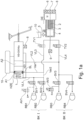
- the Figure 1a describes the basic embodiment of the brake system according to the invention with master brake cylinder HZE, pressure supply unit DE with single-stroke piston (3) and outlet valve(s) AV1, AV3 in one or optionally 2 brake circuits.
- Brake circuit II is advantageously assigned to the front axle.
- the outlet valve AV1 is optional, ie it does not necessarily have to be provided.
- the braking system consists of a master brake cylinder according to the state of the art consisting of a master brake cylinder unit HZE, floating piston SK with return spring 1, a pressure piston DK or tappet or an auxiliary piston HiKo, a hydraulically confirmed travel simulator WS and with corresponding control valves HZV for the functions of the piston-cylinder unit as described, for example, in the state of the art.
- the master brake cylinder unit HZE can be separated from the pressure supply unit DE. According to variant Var2, this can be done via the isolating valves TV1 and TV2 or, in the second variant Var1 shown, by blocking the supply to the floating piston.
- the valve circuit of the HZE ensures that there is no undesirable reaction to the pedal BP when the pressure supply unit DE is active and that in the fallback level (system failure) the volume of the master brake cylinder unit HZE is fed into the wheel brakes RB1-4.
- each wheel brake has a switching valve SV1-4 in the hydraulic connection to the respective associated working chamber A1 or A2 of the master brake cylinder HZE.
- the specific design of the master brake cylinder HZE is not relevant for the brake system according to the invention.
- the pressure generator unit DE is preferably arranged in the valve block or HZE.
- the pressure chamber 4 of the pressure generator unit DE is connected to the reservoir 10 by a check valve 5.
- a pressure sensor 9 is arranged at the outlet of the pressure generator unit DE.
- the brake circuit II is connected to the pressure supply unit DE via the isolating valve TV2 and the brake circuit I via the isolating valve TV1.
- the isolating valve TV1 can be omitted by separating a chamber with the pressure supply unit DE in the fallback level. This can be done by supplying pressure from the pressure generator unit DE via the sniffer hole SL of the floating piston SK.
- the control device and its regulator determine the necessary pressure change for pressure build-up (hereinafter referred to as Pauf) and pressure reduction (hereinafter referred to as pab).
- the pressure control is carried out by the pressure generator unit DE, in which the individual wheels/wheel cylinders are supplied with pressure simultaneously or at different times. To do this, the electric motor M shifts the corresponding volume for the pressure change in both directions via the piston 3, for example.
- the pressure change could be changed according to the state of the art by appropriate time control with PMW of the switching valves and pressure control of the pressure of the DE.
- volume control is preferably used, as already described above.
- the data of the pressure-volume characteristic curve (pV characteristic curve - see Figure 1a and 2a ) of the wheel brake RB1-4 involved in the pressure build-up or pressure reduction is stored in the controller's memory. If the controller now requests a pressure change ⁇ p, the differential volume ⁇ v is adjusted accordingly by the piston in both directions t S to regulate the pressure at the wheel.
- one or more switching valves are opened, which are closed again once the volume shift has ended.
- the position of piston 3, e.g. start of stroke or middle of stroke, end, is irrelevant for the ⁇ P volume control.
- a time control can be used during the pressure change to implement transition functions towards the end of the pressure change, e.g. to reduce pressure oscillations and the associated noise.
- High dynamics are important when two or more wheels require a pressure change at the same time.
- the invention proposes that one or two additional outlet valves AV are used to relieve the engine dynamics.
- the pressure level in the pressure generator unit DE and in the wheels is also particularly important for volume control. It is advantageous that the pressure level when the pressure changes corresponds to the output pressure of the wheel to be controlled. This achieves fast and quiet pressure control.
- the time sequences are set in Figures 3, 3a, 3b and Figures 4, 4a, 4b shown.
- All pumps with single pistons, stepped pistons, double-acting pistons or, for example, gear pumps that enable precise volume control can be used as pressure generating units DE.
- pressure is generated in a single circuit directly via a isolating valve TV1 in BK1 (Var2) or alternatively via a sniffer hole SL on the front of the SK piston (Var1).
- the pressure is supplied to the BK2 brake circuit via an isolating valve TV2.
- the isolating valve TV1 can optionally be omitted, since in the event of a system failure, the pressure generating unit DE is separated from the master brake cylinder effect by the piston SK moving and cutting off the pressure supply DE.
- the pressure generating unit DE can be connected directly to BK1 via the TV1 (Var 2), as shown in dashed lines. Since the SK piston in Var. 1 is only moved in the fallback level, a special diagnostic circuit is required in which the floating piston SK is moved and checked for leaks.
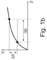
- the Figure 1b describes the known pressure control based on a simplified pressure volume characteristic curve, which is the basis of the MUX control. According to the required pressure difference ⁇ p, a volume change ⁇ V is read from a characteristic curve, which is converted into a path change As of the piston 3 by adjusting the plunger of the pressure generator unit DE. This applies to both pressure build-up and pressure reduction.
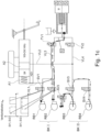
- the pressure reduction pab via the switching valves SV1 and SV2 in the BK I is mainly carried out sequentially or simultaneously via the pressure volume control.
- the respective switching valve SVi is always open.
- it is optionally possible to deviate from the MUX control by opening the switching valves SV1 and SV2 at different times and controlling the pressure reduction pab via a switching valve SV2.
- the isolating valve TV1 is continuously open during pressure reduction.
- the wheel brake RB1 has a higher pressure, so the associated switching valve SV1 is opened before the switching valve SV2.
- the time control can be precisely dimensioned.
- the switching valve SV2 is then opened when the pressure of the pressure generator unit DE is almost reached. Further pressure reduction then takes place simultaneously in both wheel brake cylinders RB1 and RB2 by controlling piston 3 with open switching valves SV1, SV2 and TV1. If the target pressure of a wheel is reached, the corresponding switching valve SV1 or SV2 is closed. If further pressure reduction in a wheel is desired, further pressure reduction can then take place in the respective wheel brake.
- PWM control is preferably omitted in order to simplify the system, especially to reduce noise.
- the Figure 1d shows a conventional valve circuit for ABS with four inlet valves EV and four outlet valves AV. If this is also to be used with less AV for MUX with, for example, differential pressure at MUX, then in addition to this pressure, the error case must be taken into account that, on an asymmetrical road surface, the pressure generator unit and also the valve control suddenly fail, e.g. by ECU, and the pressure generator unit is at the same time at a low pressure level. In this case, for example, EVI would have: 130 bar and EV2: 0 bar. If the pressure generator unit fails, this means that with EVI the return spring of the valve armature must open at around 130 bar. To make this possible, the magnetic circuit of the valve must be correspondingly large, which makes the valve expensive. As an alternative, a pressure-relieved valve can be used, but this is also expensive.
- valve seat When dimensioning the valve seat, it must also be taken into account that it should be as large as possible in order to generate a small dynamic pressure if the brake pressure is to be built up quickly by the pressure generator unit.
- the dynamic pressure is directly reflected in the engine torque and power.
- the Figure 1e shows a change in the flow through the switching valves SV.
- the hydraulic medium flows from the brake circuit or the pressure generator unit via the armature chamber to the valve seat and the wheel cylinder. If the above-mentioned error occurs, the wheel pressure opens the switching valve. However, the magnetic force must also close at 130 bar, which occurs with a small armature air gap in the valve end position.
- the return spring of the switching valves SV therefore only needs to be strengthened slightly so that the switching valve does not "tear shut" at a correspondingly high volume flow. Since conventional inlet valves must close at up to 220 bar - at Fig. 1e 130 bar -, the valve seat area can be increased with the same magnet dimensions, which means a lower back pressure or flow resistance and is advantageous for MUX operation.
- the Figure 1e The valve circuit shown is therefore advantageous for the braking system according to the invention.
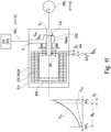
- the Figure 1f shows a possible design of the inlet valve EV according to the invention and the connection to the brake circuit BK as well as the pressure supply DV and the edge brakes RBi.
- the inlet valve EV has a magnet armature MA, a magnetic base body MGK and an excitation coil ES. If the solenoid valve EV is energized, the magnetic force MK moves the armature MA from the position SA o to the position SA2 by the differential travel SA. The magnet armature MA moves a tappet MStö by the same distance so that the tappet MStö comes into contact with the valve seat VS and closes the outlet Ea of the solenoid valve.
- the armature MA still has a residual air gap S0 to the magnetic base body MKG, which is intended to ensure that the armature MA does not stick to the magnet housing MGK due to remagnetization losses in the iron circuit when the current to the excitation coil ES of the valve EV is switched off.
- the return spring RF moves the armature MA back to its starting position when the valve current is switched off.
- the magnetic force FM increases non-linearly with a smaller air gap, i.e. with an increasing travel.
- the return spring FRF is dimensioned such that the magnetic force FM in the initial position SA o is greater than the spring force to ensure that the valve closes securely.
- the spring force increases with increasing travel SA and is also less than the magnetic force FM in the end position SA2.
- a linear spring is preferably used so that the magnetic force FM in the end position for a given current is significantly higher than the return force, so that the valve can be held with low current and secure closing is ensured even with high differential pressures between the wheel brake and the pressure supply. Holding is also ensured even with high differential pressures because the magnetic force increases in a highly non-linear manner when the valve is in the closed position.
- the return spring must also be dimensioned such that it functions as a normally open valve and the valve always opens safely.
- the output Ea of the valve is connected to the wheel brakes RBi (RB1-RB4), the input E to a brake circuit BKi or to the pressure supply unit DV (20).
- the inlet valve EV can be opened both by the return spring RF and by the pressure in the wheel brake, which is particularly important in the event of a fault or malfunction of the braking system (e.g. failure of the voltage at the valve).
- the pressure difference between the inlet Ei and outlet Ea acts on the tappet MStö.
- the Figure 2a shows the pressure-volume characteristic curve of a wheel / wheel cylinder with connecting lines to the switching valve SV and pressure sensor. Two characteristic curves are shown. Characteristic curve Paufa corresponds to a so-called stiff characteristic curve, the other characteristic curve Pauf requires considerably more volume. In extreme cases, this causes steam bubbles due to clearance or poor ventilation, for example.
- This characteristic curve For example, for pauf and pab, the memory of the control device is recorded for the first time during the end-of-line inspection i, both for the individual wheel brakes and for the brake circuits, both pauf and pab. During each braking operation, the characteristic curve is measured by comparing the pressure P with the volume V(AS). If a larger deviation occurs, the characteristic curves can be recorded or adapted when the vehicle is stationary, as in the above-mentioned inspection.
- the characteristic curves behave similarly but with a larger volume for the corresponding pressure value.
- the p-V characteristic curves for the pressure build-up pauf and the pressure reduction pab are used for control.
- the Figure 2b describes the relevant pressure-volume characteristics simplified for pressure control without hysteresis in the closed brake circuit or displacement after pressure reduction with the outlet valve AV open.
- the required volume displacement ⁇ v or displacement change As of the piston is read from the characteristic curve by assigning the target pressure differential ⁇ p. These differ and depend on whether the pressure is changed in one or more brake circuits.
- the piston is then moved accordingly. If the pressure is reduced via one or more outlet valves, there is a loss of volume in the pressure generator unit.
- the displacement assignment of the pressure-volume characteristic curve is determined by recording the pressure.
- Figure 3 shows a timing diagram of the MUX control as shown in WO
- the Figure 3 shows the pressure curve in the individual wheel brakes over time in a conventional MUX operation, in which the pressure in the wheel brakes is reduced one after the other.
- VI and V2 are the front wheel brakes
- H1 and H2 are the rear axle brakes.
- the signal for simultaneous pressure reduction pab is given.
- the response time tv SV of the switching valve SV is approx. 5ms.
- the response time tv M for the motor is approx. 10ms. This takes into account that the piston of the pressure generator unit must first position itself for the different pressure levels of the individual wheels before the pressure change at (1).
- the pressure reduction pab then takes place with the assumption of tab of approx. 10 ms, during which time the pressure is reduced by ⁇ p equal to approx. 20 bar.
- the ABS controller In conventional ABS systems with 4 inlet and 4 outlet valves, the ABS controller always determines a ⁇ p and then determines the time for which the outlet valve must be opened so that the required pressure reduction occurs in the wheel brake. This time control is known to be subject to tolerance, which limits the accuracy of the pressure control. In addition, when the outlet valve AV closes, pressure oscillations always occur, which cause detrimental noise.
- the motor then adjusts to the pressure reduction pab from the front wheel V2, which then also occurs after SV2 opens.
- FIG 3a The temporal pressure curve for the control concept according to the invention is shown.
- the pressure reduction pab at the front wheel brake VI at time (1) corresponds to (1) in Figure 3 .
- the additional outlet valve AV is used to reduce the pressure pab.
- the pressure reduction Pab takes place with almost no delay at (11) via a time control t described above, with the pressure oscillation occurring at (12) after SV2 is closed. This means that the control of the front wheels VI and V2, which make a significantly greater contribution to the braking force than the rear wheels at high- ⁇ , is almost not delayed.
- the motor is already prepared at (13) for the pressure change at the rear wheel H1. This then takes place at (14) to (15) by volume control using the pressure generator unit DE.
- a simultaneous pressure reduction pab can take place using volume control.
- a time-controlled pressure reduction pab can also take place in the brake circuit at H2 at (16). The prerequisite for this is that the MUX pressure level in the wheel brake of the rear wheel H2 is lower than that of the rear wheel H1, where the pressure reduction takes place via volume control. It is also possible that the pressure reduction in the rear wheel brake H2 takes place via a time-controlled opening of the associated outlet valve.
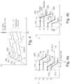
- the Figure 4 - 4b show the pressure curve with different real pressure levels and variants of the front and rear wheels HI, H2, VI and V2 in the control concept according to the invention.
- Figure 4 shows the temporal pressure curve VI to H2 in different phases.
- phase 0-X a pressure curve is shown in which due to different pressure levels in the wheel brakes no simultaneous pressure build-up Piller and pressure reduction pab can take place, which is the case most often.
- full multiplex operation is also effective here, ie precise ⁇ p control via volume control for both the pressure build-up piller and the pressure reduction pab -
- the pressure builds up pauf sometimes e.g. at 20 with a simultaneous pressure build-up demand
- a time-delayed pressure build-up pauf at H1 and H2 will take place.
- a partially simultaneous pressure build-up Piller can also take place.
- a partially simultaneous pressure reduction is also possible, as is the case in Figure 4b shown is possible.
- the Figure 4a shows variant A again starting from the starting point X with Pab at VI and V2 as in Figure 3a described.
- the pressure reduction pab takes place by means of volume control via the pressure generator unit DE.
- This pressure reduction takes place when there is sufficient differential pressure ⁇ p between H2-V1.
- the pressure levels of all wheels are known in the inventive control concept or MUX method, so that a relatively precise pressure reduction pab in the rear wheel H2 is also achieved via time control, i.e. the opening of the switching valve SVH2.
- the necessary opening time t can also be flexibly adjusted based on the change in the pressure level of M1 (MUX).
- the pressure reduction pab of the rear wheel H1 also takes place via volume control, starting from the preparation at 13 and then by opening the associated switching valve at 22.
- Figure 4b shows variant B for partially simultaneous pressure reduction at the rear wheels H1 and H2, starting from a relatively small pressure difference between the rear wheels H1 and H2.
- the pressure reduction pab takes place at 23 with MUX, i.e. volume control using the pressure generator unit.
- the rear wheel H2 is switched into the pressure reduction pab by opening the switching valve SVH2 belonging to the rear wheel H2.
- the controlled pressure reduction pab for H2 is achieved, which is why the switching valve SVH2 is closed.
- the ⁇ p for the rear wheel H1 is then achieved via the volume control, which is why the switching valve SVH I is closed at 26.
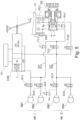
- the Figure 5 describes a further embodiment of the pressure supply unit DE according to the invention with pressure control with master brake cylinder, master brake cylinder valves HZV, pressure supply with double-acting piston switching and outlet valve(s).
- the pressure in the pre-stroke chamber of the pressure supply unit DE cannot be determined precisely because pressure is being reduced via ZAV in wheel brake RB4 at the same time and TV2 is closed, the pressure in the pre-stroke chamber can be used via pressure estimation p/i from the torque of the electric motor.
- the switching valve SV2 is then opened when the pressure of the pressure generator unit DE is almost reached. Further pressure reduction then takes place simultaneously in both wheel brake cylinders by controlling piston 3 with SV1, SV2 and TV1 open. If the target pressure of a particular wheel is reached, the corresponding valve SV1 or SV2 is closed. If further pressure reduction is desired in a wheel, further pressure reduction can then only take place in one wheel brake.
- the pressure in BK II can be reduced using the time control of AV3.
- the timing of this can be freely determined because closing SV3 does not affect the other wheel brake cylinders.
- the timing of the pressure reduction in wheel brake RB4 can also be freely selected when the pressure in BK I is reduced in MUX mode.
- a locking element SE can be arranged in the BK1 or BK2, which acts directly on the SK as a mechanical block.
- the locking element can also be part of the HZV.
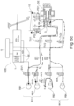
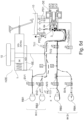
- the Figure 6 describes a system with double-stroke pistons in an advantageous two-circuit design.
- the structure of THZ, DE and valve circuit for pressure control ABS with MUX and AV is identical to Figure 5c .
- This valve circuit results in the floating piston position being such that the return spring 1 moves the floating piston SK to the right stop or remains in the middle position.
- the pressure sensor 9 measures the pressure in the BK II and can evaluate the pressure in both brake circuits for the regulation and control functions in the case of a "single-circuit" circuit.
- This system also includes the additional potential to reduce the pressure in BK II via the DHK piston 3 and separately from BK I via the valves TV2b and PD1.
Landscapes
- Engineering & Computer Science (AREA)
- Transportation (AREA)
- Mechanical Engineering (AREA)
- Physics & Mathematics (AREA)
- Fluid Mechanics (AREA)
- Electromagnetism (AREA)
- Regulating Braking Force (AREA)
- Braking Systems And Boosters (AREA)
- Transmission Of Braking Force In Braking Systems (AREA)
- Valves And Accessory Devices For Braking Systems (AREA)
Applications Claiming Priority (6)
| Application Number | Priority Date | Filing Date | Title |
|---|---|---|---|
| DE202015107075 | 2015-03-16 | ||
| DE202015107079.9U DE202015107079U1 (de) | 2015-03-16 | 2015-03-16 | Bremssystem mit gemeinsamem Auslassventil für beide Bremskreise |
| DE202015107072 | 2015-03-16 | ||
| PCT/EP2015/081402 WO2016146223A2 (fr) | 2015-03-16 | 2015-12-30 | Système de freinage à régulation mux innovante (mux 2.0) équipé d'une soupape de sortie/ou équipé d'une soupape de sortie par circuit de freinage et procédé servant à la régulation de pression |
| EP23207002.9A EP4292893B1 (fr) | 2015-03-16 | 2015-12-30 | Procédé de régulation de pression |
| EP15823175.3A EP3271221B1 (fr) | 2015-03-16 | 2015-12-30 | Système de freinage à régulation mux innovante (mux 2.0) équipé d'une soupape de sortie/ou équipé d'une soupape de sortie par circuit de freinage et procédé servant à la régulation de pression |
Related Parent Applications (3)
| Application Number | Title | Priority Date | Filing Date |
|---|---|---|---|
| EP23207002.9A Division EP4292893B1 (fr) | 2015-03-16 | 2015-12-30 | Procédé de régulation de pression |
| EP23207002.9A Division-Into EP4292893B1 (fr) | 2015-03-16 | 2015-12-30 | Procédé de régulation de pression |
| EP15823175.3A Division EP3271221B1 (fr) | 2015-03-16 | 2015-12-30 | Système de freinage à régulation mux innovante (mux 2.0) équipé d'une soupape de sortie/ou équipé d'une soupape de sortie par circuit de freinage et procédé servant à la régulation de pression |
Publications (4)
| Publication Number | Publication Date |
|---|---|
| EP4446182A2 true EP4446182A2 (fr) | 2024-10-16 |
| EP4446182A3 EP4446182A3 (fr) | 2025-01-22 |
| EP4446182B1 EP4446182B1 (fr) | 2026-02-04 |
| EP4446182C0 EP4446182C0 (fr) | 2026-02-04 |
Family
ID=55066639
Family Applications (4)
| Application Number | Title | Priority Date | Filing Date |
|---|---|---|---|
| EP24194897.5A Active EP4446182B1 (fr) | 2015-03-16 | 2015-12-30 | Système de freinage à décompression partiellement simultanée en système ouvert et fermé |
| EP23207002.9A Active EP4292893B1 (fr) | 2015-03-16 | 2015-12-30 | Procédé de régulation de pression |
| EP15823175.3A Active EP3271221B1 (fr) | 2015-03-16 | 2015-12-30 | Système de freinage à régulation mux innovante (mux 2.0) équipé d'une soupape de sortie/ou équipé d'une soupape de sortie par circuit de freinage et procédé servant à la régulation de pression |
| EP15817915.0A Active EP3271220B1 (fr) | 2015-03-16 | 2015-12-30 | Système de freinage à régulation de montée en pression avec câblage spécial, vannes d'entrée à circuit de freinage/freins et procédé de régulation de pression |
Family Applications After (3)
| Application Number | Title | Priority Date | Filing Date |
|---|---|---|---|
| EP23207002.9A Active EP4292893B1 (fr) | 2015-03-16 | 2015-12-30 | Procédé de régulation de pression |
| EP15823175.3A Active EP3271221B1 (fr) | 2015-03-16 | 2015-12-30 | Système de freinage à régulation mux innovante (mux 2.0) équipé d'une soupape de sortie/ou équipé d'une soupape de sortie par circuit de freinage et procédé servant à la régulation de pression |
| EP15817915.0A Active EP3271220B1 (fr) | 2015-03-16 | 2015-12-30 | Système de freinage à régulation de montée en pression avec câblage spécial, vannes d'entrée à circuit de freinage/freins et procédé de régulation de pression |
Country Status (7)
| Country | Link |
|---|---|
| US (4) | US11760329B2 (fr) |
| EP (4) | EP4446182B1 (fr) |
| JP (3) | JP6941056B2 (fr) |
| KR (2) | KR20170128544A (fr) |
| CN (4) | CN107428317A (fr) |
| DE (1) | DE202015008976U1 (fr) |
| WO (2) | WO2016146224A1 (fr) |
Families Citing this family (35)
| Publication number | Priority date | Publication date | Assignee | Title |
|---|---|---|---|---|
| CN107428317A (zh) | 2015-03-16 | 2017-12-01 | 爱皮加特股份公司 | 具有借助入口阀的特殊布线进行压力形成调节的具有制动回路/车轮制动器的制动装置和用于压力调节的方法 |
| WO2016146222A2 (fr) | 2015-03-16 | 2016-09-22 | Ipgate Ag | Système de freinage équipé d'une unité à maître-cylindre de frein à régulation mux innovante (mux 2.0) comprenant au moins une soupape de sortie, et procédé servant à la régulation de pression |
| US10328913B2 (en) * | 2016-11-18 | 2019-06-25 | International Business Machines Corporation | Facilitation of automatic adjustment of a braking system |
| DE102017111077A1 (de) | 2017-05-22 | 2018-11-22 | Lsp Innovative Automotive Systems Gmbh | Bremsvorrichtung, insbesondere für elektrisch angetriebene Kraftfahrzeuge |
| DE102017114556A1 (de) | 2017-06-29 | 2019-01-03 | Ipgate Ag | Vorrichtung für ein hydraulisches Betätigungssystem |
| CN111511617B (zh) | 2017-12-27 | 2023-01-06 | 罗伯特·博世有限公司 | 用于液压系统的实时压力-体积曲线生成 |
| DE102018206566A1 (de) * | 2018-04-27 | 2019-10-31 | Robert Bosch Gmbh | Fahrzeugbremssystem und Verfahren zur Bremsdrucksteigerung in einem ersten Radbremszylinder und Bremsdruckbegrenzung in einem zweiten Radbremszylinder eines Fahrzeugbremssystems |
| DE102018111126A1 (de) | 2018-05-09 | 2019-11-14 | Ipgate Ag | Bremssystem, insbesondere für automatisiertes Fahren |
| DE102018115365A1 (de) * | 2018-06-26 | 2020-01-02 | Lsp Innovative Automotive Systems Gmbh | Vorrichtung zur Ansteuerung von mehreren Stellgliedern mit einem gemeinsamen getakteten Auslassventil zum Druckabbau |
| DE102018211051A1 (de) | 2018-07-04 | 2020-01-09 | Volkswagen Aktiengesellschaft | Verfahren zur Steuerung der Bremskraft in einer elektrohydraulischen Bremsanlage eines Kraftfahrzeugs |
| DE102018220557A1 (de) * | 2018-11-29 | 2020-06-04 | Robert Bosch Gmbh | Verfahren zur Ermittlung eines zukünftigen Radbremsdrucks einer hydraulischen Fahrzeugbremsanlage |
| DE102018221079A1 (de) * | 2018-12-06 | 2020-06-10 | Robert Bosch Gmbh | Verfahren zur Prüfung einer elektronisch schlupfregelbaren Bremsanlage für ein Kraftfahrzeug auf vorliegende Störungen |
| DE102018133189A1 (de) | 2018-12-20 | 2020-06-25 | Ipgate Ag | Redundantes Bremssystem mit 2 Druckversorgungen für Elektrofahrzeuge und Fahrzeuge mit autonomem Fahren der Stufe 3 (HAD) bis Stufe 5 (AD) |
| DE102018133218A1 (de) | 2018-12-20 | 2020-06-25 | Ipgate Ag | Redundantes Bremssystem mit einer Druckversorgung für E-Fahrzeuge und Fahrzeuge mit autonomem Fahren der Stufe 3 (HAD) bis Stufe 4 (FAD) |
| DE102018133223A1 (de) * | 2018-12-20 | 2020-06-25 | Ipgate Ag | Fahrzeugachse mit elektrischen Antriebsmotoren und elektrohydraulischer Bremse und weiterer Module wie Getriebe, Torque Vektoring und Parkbremse |
| EP4653272A2 (fr) | 2018-12-20 | 2025-11-26 | Ipgate Ag | Système de freinage redondant avec alimentation en pression pour véhicules électriques et véhicules avec conduite autonome du niveau 3 (had) jusqu'à 4 (fad) |
| EP4501721A3 (fr) | 2018-12-20 | 2025-02-19 | Ipgate Ag | Système de freinage redondante avec deux alimentations de pression pour véhicule électrique et véhicule autonome de niveau 3 (had) à 5 (ad) |
| CN109683521B (zh) * | 2018-12-21 | 2020-11-10 | 合肥欣奕华智能机器有限公司 | 一种电控系统及制动控制方法 |
| DE202019101586U1 (de) | 2019-02-12 | 2020-05-13 | Ipgate Ag | Packaging für ein Bremssystem |
| DE102019103464A1 (de) * | 2019-02-12 | 2020-08-13 | Ipgate Ag | Hydrauliksystem mit mindestens zwei hydraulischen Kreisen und mindestens zwei Druckversorgungseinrichtungen |
| US12071118B2 (en) | 2019-02-12 | 2024-08-27 | Ipgate Ag | Pressure supply device with double stroke piston for a brake system |
| CN113631443B (zh) | 2019-02-12 | 2024-02-23 | 爱皮加特股份公司 | 具有压力供给装置和用于制动回路的安全门的制动系统 |
| DE202019101596U1 (de) | 2019-02-12 | 2020-05-13 | Ipgate Ag | Hydrauliksystem mit mindestens zwei hydraulischen Kreisen und mindestens zwei Druckversorgungseinrichtungen |
| JP2022520243A (ja) | 2019-02-12 | 2022-03-29 | アイピーゲート・アクチェンゲゼルシャフト | フェールセーフブレーキシステム |
| JP7424165B2 (ja) * | 2020-03-30 | 2024-01-30 | 株式会社アドヴィックス | 車両用制動装置 |
| DE102020212413A1 (de) * | 2020-09-30 | 2022-03-31 | Robert Bosch Gesellschaft mit beschränkter Haftung | Betriebsbremsung mit einer hydraulischen Mehrkreis-Fremdkraft-Fahrzeugbremsanlage |
| CN112339734A (zh) * | 2020-11-19 | 2021-02-09 | 宁波拓普集团股份有限公司 | 一种模块化集成的线控制动系统 |
| KR102881002B1 (ko) * | 2020-11-30 | 2025-11-03 | 현대모비스 주식회사 | 차량의 제동장치 및 그 제동방법 |
| DE102021200697A1 (de) * | 2021-01-27 | 2022-07-28 | Robert Bosch Gesellschaft mit beschränkter Haftung | Verfahren zur Steuerung einer elektronisch schlupfregelbaren Fremdkraftbremsanlage mit redundanter Bremsdruckerzeugung |
| US11801817B2 (en) * | 2021-03-04 | 2023-10-31 | ZF Active Safety US Inc. | Vehicle braking system |
| WO2022214521A1 (fr) * | 2021-04-07 | 2022-10-13 | Heinz Leiber | Système de freinage à sécurité intégrée |
| CN113460009B (zh) * | 2021-07-28 | 2022-09-23 | 中国第一汽车股份有限公司 | 一种集成式制动系统补液控制方法及车辆 |
| KR20230065817A (ko) * | 2021-11-05 | 2023-05-12 | 현대모비스 주식회사 | 차량용 전동식 브레이크 및 그 제어방법 |
| US12240427B2 (en) | 2022-03-30 | 2025-03-04 | ZF Active Safety US Inc. | Fast replenishing brake system |
| DE102022123532A1 (de) * | 2022-09-14 | 2024-03-14 | Heinz Leiber | Bremssystem sowie Ventil mit zuschaltbarer Haltekraft |
Citations (9)
| Publication number | Priority date | Publication date | Assignee | Title |
|---|---|---|---|---|
| WO2006111393A1 (fr) | 2005-04-21 | 2006-10-26 | Gerber, Wolfram | Commande de modulateur de pression |
| WO2006111392A1 (fr) | 2005-04-21 | 2006-10-26 | Wolfram Gerber | Systeme de freinage pourvu d'un systeme piston-cylindre a entrainement par moteur electrique |
| WO2010091883A1 (fr) | 2009-02-13 | 2010-08-19 | Ipgate Ag | Système de freinage à établissement ou réduction de pression simultané ou partiellement simultané dans les freins sur roues à partir de divers niveaux de pression de cylindres de freins sur roues |
| DE102011102270A1 (de) | 2011-05-23 | 2012-11-29 | Universität Stuttgart | Verfahren und Vorrichtung zur Ablation von Schichten von Halbleitersubstraten, sowie zur Nachbehandlung |
| DE102012002791A1 (de) | 2012-02-15 | 2013-08-22 | Ipgate Ag | Bremsbetätigungsvorrichtung |
| DE102013224313A1 (de) | 2013-03-05 | 2014-09-11 | Continental Teves Ag & Co. Ohg | Verfahren zum Betreiben eines Bremssystems |
| DE102013216477A1 (de) | 2013-08-20 | 2015-02-26 | Continental Teves Ag & Co. Ohg | Bremsanlage für Kraftfahrzeuge |
| DE102014117727A1 (de) | 2014-12-02 | 2016-06-02 | Ipgate Ag | Betätigungsanlage für zumindest eine hydraulisch betätigbare Einrichtung, insbesondere Fahrzeugbremse |
| DE102015103859A1 (de) | 2015-03-16 | 2016-09-22 | Ipgate Ag | Hydraulische Einrichtung, insbesondere Bremseinrichtung für Kraftfahrzeuge |
Family Cites Families (75)
| Publication number | Priority date | Publication date | Assignee | Title |
|---|---|---|---|---|
| US3515439A (en) | 1968-05-01 | 1970-06-02 | Ford Motor Co | Automatic control circuit for an antiskid braking system in an automotive vehicle driveline |
| US3870377A (en) | 1972-07-15 | 1975-03-11 | Itt | Brake pressure modulator |
| DE3423029A1 (de) | 1984-06-22 | 1986-02-20 | Alfred Teves Gmbh, 6000 Frankfurt | Hydraulische servofahrzeugbremse |
| DE3705311C2 (de) | 1987-02-19 | 1998-08-20 | Teves Gmbh Alfred | Mehrkreisige hydraulische Bremsanlage für Kraftfahrzeuge |
| DE19537962A1 (de) | 1995-10-12 | 1997-04-17 | Teves Gmbh Alfred | Elektronisch regelbares Bremsbetätigungssystem |
| DE19600603B4 (de) * | 1996-01-10 | 2005-01-27 | Continental Teves Ag & Co. Ohg | Hydraulische Bremsanlage für ein Kraftfahrzeug |
| DE19601268A1 (de) | 1996-01-16 | 1997-07-17 | Teves Gmbh Alfred | Hydraulische Bremsanlage mit Antriebsschlupfregelung |
| DE19601417A1 (de) * | 1996-01-17 | 1997-07-24 | Teves Gmbh Alfred | Blockiergeschützte hydraulische Bremsanlage mit einer Einrichtung zur Aktivbremsung |
| AU8279598A (en) * | 1997-06-30 | 1999-01-19 | Kelsey-Hayes Company | Braking system with remote boost valve |
| JP3752853B2 (ja) | 1998-07-14 | 2006-03-08 | 日産自動車株式会社 | 制動力制御装置 |
| JP3793366B2 (ja) | 1999-05-28 | 2006-07-05 | 日信工業株式会社 | ブレーキ用油圧倍力装置 |
| WO2000074987A1 (fr) | 1999-06-08 | 2000-12-14 | Continental Teves Ag & Co. Ohg | Systeme de freinage a reglage electronique |
| DE19963763B4 (de) * | 1999-12-30 | 2010-06-17 | Robert Bosch Gmbh | Verfahren und System zum Betreiben einer schlupfgeregelten Bremsanlage eines Fahrzeugs |
| ATE261348T1 (de) | 2000-08-08 | 2004-03-15 | Bosch Rexroth Ag | Antriebsvorrichtung, insbesondere für die schliesseinheit, die einspritzeinheit oder die auswerfer einer kunststoffspritzgiessmaschine |
| JP4288854B2 (ja) | 2000-08-16 | 2009-07-01 | トヨタ自動車株式会社 | ブレーキ装置 |
| JP3941388B2 (ja) | 2000-12-21 | 2007-07-04 | トヨタ自動車株式会社 | 車輌の制動制御装置 |
| WO2003038246A2 (fr) | 2001-10-19 | 2003-05-08 | Robert Bosch Gmbh | Actionneur hydraulique pour soupape a deux voies a gaz |
| DE10348831A1 (de) | 2003-01-30 | 2004-09-23 | Continental Teves Ag & Co. Ohg | Bremsanlage |
| US6896338B2 (en) * | 2003-04-18 | 2005-05-24 | Continental Teves Inc. | Hydraulic braking system featuring selectable increased pump flow |
| JP4281525B2 (ja) | 2003-11-20 | 2009-06-17 | 日産自動車株式会社 | 車両のブレーキ装置 |
| DE102004014171A1 (de) * | 2004-02-10 | 2006-03-23 | Continental Teves Ag & Co. Ohg | Fahrzeugbremssystem und Verfahren zum Betreiben des Fahrzeugbremssystems |
| CN101039830A (zh) | 2004-10-15 | 2007-09-19 | 大陆-特韦斯贸易合伙股份公司及两合公司 | 用于机动车辆的制动设备 |
| JP4742716B2 (ja) | 2005-07-19 | 2011-08-10 | 株式会社アドヴィックス | アンチスキッド制御装置 |
| DE102006030791A1 (de) | 2006-06-30 | 2008-01-03 | Zf Friedrichshafen Ag | Hydrodynamischer Retarder |
| US20080179944A1 (en) * | 2007-01-29 | 2008-07-31 | Continental Teves, Inc. | Hydraulic anti-lock brake system |
| US20080216643A1 (en) * | 2007-03-07 | 2008-09-11 | Cano Jose R | Biased actuator systems |
| JP4874172B2 (ja) | 2007-06-15 | 2012-02-15 | 日立オートモティブシステムズ株式会社 | 二輪車用ブレーキ制御装置 |
| JP2009067262A (ja) | 2007-09-14 | 2009-04-02 | Hitachi Ltd | ブレーキ制御装置およびその制御方法 |
| EP2225132B1 (fr) * | 2007-12-21 | 2011-09-14 | Ipgate Ag | Système de freinage comprenant au moins un dispositif de refoulement pour le post-refoulement de liquide de frein vers les chambres de travail du servofrein |
| DE102008003664B4 (de) | 2008-01-09 | 2023-03-23 | Robert Bosch Gmbh | Bremssystem und Verfahren zum Betreiben eines Bremssystems |
| JP5005555B2 (ja) | 2008-01-10 | 2012-08-22 | 本田技研工業株式会社 | ブレーキ装置 |
| JP5304446B2 (ja) * | 2008-08-28 | 2013-10-02 | 株式会社アドヴィックス | 調圧リザーバ |
| DE102009001745A1 (de) | 2009-03-23 | 2010-09-30 | Robert Bosch Gmbh | Klauenpol mit Zentrierpunkt |
| DE102010038327A1 (de) | 2009-08-14 | 2011-02-17 | Continental Teves Ag & Co. Ohg | Bremsanlage für Kraftfahrzeuge |
| JP5240123B2 (ja) | 2009-08-24 | 2013-07-17 | トヨタ自動車株式会社 | 液圧制御装置 |
| DE102009043484B4 (de) | 2009-09-30 | 2018-05-03 | Ipgate Ag | Bremssystem für ein Hybridfahrzeug und Verfahren zu seinem Betrieb |
| DE102010008033A1 (de) * | 2010-02-13 | 2011-08-18 | Ipgate Ag | Bremssystem mit Druckmodell und Priorisierungseinrichtung |
| DE102010002406B4 (de) | 2010-02-26 | 2012-01-26 | Robert Bosch Gmbh | Hydraulisches Bremssystem und Verfahren sowie Steuergerät zu dessen Betrieb |
| DE102010020002B4 (de) | 2010-05-10 | 2024-03-28 | Zf Active Safety Gmbh | Hydraulikbaugruppe für eine Fahrzeug-Bremsanlage |
| DE102011076675A1 (de) * | 2010-06-10 | 2011-12-15 | Continental Teves Ag & Co. Ohg | Verfahren und Vorrichtung zur Regelung eines elektrohydraulischen Bremssystems für Kraftfahrzeuge |
| DE102011077329A1 (de) | 2010-07-23 | 2012-01-26 | Continental Teves Ag & Co. Ohg | Verfahren zur Regelung eines elektrohydraulischen Bremssystems sowie elektrohydraulisches Bremssystem |
| US8875054B2 (en) | 2010-07-30 | 2014-10-28 | Apple Inc. | Hybrid knob/slider control |
| DE102011080312B4 (de) | 2010-08-05 | 2024-11-21 | Continental Automotive Technologies GmbH | Bremsanlage für Kraftfahrzeuge |
| US9067577B2 (en) | 2010-08-06 | 2015-06-30 | Honda Motor Co., Ltd. | Vehicle braking system |
| DE102010040577B4 (de) | 2010-09-10 | 2024-02-22 | Robert Bosch Gmbh | Bremssystem für ein Fahrzeug |
| DE102010050132A1 (de) | 2010-11-03 | 2012-05-03 | Ipgate Ag | Betätigungsvorrichtung mit Wegsimulator |
| DE102010051744A1 (de) | 2010-11-19 | 2012-05-24 | Ipgate Ag | Hydraulisches System, insbesondere Bremssyystem |
| DE102011002966A1 (de) | 2011-01-21 | 2012-07-26 | Robert Bosch Gmbh | Bremssystem für ein Fahrzeug und Verfahren zum Betreiben eines Bremssystems für ein Fahrzeug |
| DE102012205860A1 (de) | 2011-04-19 | 2012-10-25 | Continental Teves Ag & Co. Ohg | Bremsanlage für Kraftfahrzeuge |
| DE102011118365A1 (de) | 2011-11-14 | 2013-05-16 | Ipgate Ag | Elektronisch regelbares Bremsbestätigungssystem |
| DE102012201515A1 (de) | 2012-02-02 | 2013-08-08 | Continental Teves Ag & Co. Ohg | Verfahren zum Betrieb einer Bremsanlage für Kraftfahrzeuge sowie Bremsanlage |
| DE102012222897A1 (de) * | 2012-02-28 | 2013-08-29 | Continental Teves Ag & Co. Ohg | Verfahren zum Betrieb einer Bremsanlage |
| DE102013203594A1 (de) * | 2012-03-06 | 2013-09-12 | Continental Teves Ag & Co. Ohg | Verfahren zum Betreiben einer Bremsanlage für Kraftfahrzeuge sowie Bremsanlage |
| DE102013203589A1 (de) * | 2012-03-06 | 2013-09-12 | Continental Teves Ag & Co. Ohg | Verfahren zum Betreiben einer Bremsanlage sowie Bremsanlage |
| DE102013204778B4 (de) | 2012-03-22 | 2026-03-26 | Aumovio Germany Gmbh | Verfahren zur haptischen Information des Fahrers eines Kraftfahrzeugs |
| DE102012009360A1 (de) | 2012-05-10 | 2013-11-14 | Lucas Automotive Gmbh | Verfahren zum Betreiben eines elektronisch steuerbaren Bremssystems |
| JP5768935B2 (ja) | 2012-05-25 | 2015-08-26 | トヨタ自動車株式会社 | 調圧器、および、それを備えた液圧ブレーキシステム |
| DE102012025247B4 (de) * | 2012-12-21 | 2025-04-17 | Zf Active Safety Gmbh | Elektrohydraulische Fahrzeug-Bremsanlage und Verfahren zum Betreiben derselben |
| DE102013222061A1 (de) * | 2013-03-25 | 2014-09-25 | Continental Teves Ag & Co. Ohg | Verfahren zum Betrieb einer Bremsanlage für Kraftfahrzeuge |
| KR20140134016A (ko) | 2013-05-13 | 2014-11-21 | 현대모비스 주식회사 | 통합형 제동시스템 |
| KR102033892B1 (ko) | 2013-05-14 | 2019-10-18 | 현대모비스 주식회사 | 전자식 유압 브레이크장치 |
| DE102013210563A1 (de) * | 2013-06-06 | 2014-12-11 | Continental Teves Ag & Co. Ohg | Verfahren zur Steuerung und Regelung eines elektrohydraulischen Bremssystems und Bremssystem |
| DE102013014188A1 (de) * | 2013-08-26 | 2015-02-26 | Lucas Automotive Gmbh | Elektrohydraulische Fahrzeug-Bremsanlage mit elektromechanischem Aktuator und Verfahren zum Betreiben der Bremsanlage |
| DE102013014173A1 (de) | 2013-08-26 | 2015-02-26 | Lucas Automotive Gmbh | Elektrohydraulische Fahrzeug-Bremsanlage mit elektromechanischem Aktuator und Verfahren zum Betreiben der Bremsanlage |
| DE102013218121A1 (de) * | 2013-09-11 | 2015-03-12 | Continental Teves Ag & Co. Ohg | Elektromagnetventil, insbesondere für schlupfgeregelte Kraftfahrzeug-Bremsanlagen |
| DE102013110188A1 (de) | 2013-09-16 | 2015-03-19 | Ipgate Ag | Betätigungsvorrichtung für eine Kraftfahrzeug-Bremsanlage |
| CN110576840B (zh) | 2013-09-16 | 2022-02-01 | 爱皮加特股份公司 | 制动设备和用于制动设备的运行的方法 |
| WO2015036623A2 (fr) | 2013-09-16 | 2015-03-19 | Ipgate Ag | Unité de refoulement à débit volumique et régulation de pression, à commande électrique |
| DE102014107112A1 (de) | 2014-05-20 | 2015-11-26 | Ipgate Ag | Betätigungssystem für eine Fahrzeugbremse und Verfahren zum Betrieb des Betätigungssystems |
| KR101622152B1 (ko) * | 2014-12-09 | 2016-06-01 | 주식회사 만도 | 전자식 브레이크 시스템 |
| WO2016146222A2 (fr) | 2015-03-16 | 2016-09-22 | Ipgate Ag | Système de freinage équipé d'une unité à maître-cylindre de frein à régulation mux innovante (mux 2.0) comprenant au moins une soupape de sortie, et procédé servant à la régulation de pression |
| CN107428317A (zh) | 2015-03-16 | 2017-12-01 | 爱皮加特股份公司 | 具有借助入口阀的特殊布线进行压力形成调节的具有制动回路/车轮制动器的制动装置和用于压力调节的方法 |
| KR102473927B1 (ko) * | 2015-10-19 | 2022-12-06 | 에이치엘만도 주식회사 | 전자식 브레이크 시스템의 진단방법 |
| DE102016203563A1 (de) | 2016-03-04 | 2017-09-07 | Continental Teves Ag & Co. Ohg | Bremsanlage mit zwei Druckbereitstellungseinrichtungen sowie Verfahren zum Betreiben einer Bremsanlage |
| DE102018205089A1 (de) | 2018-04-05 | 2019-10-10 | Continental Teves Ag & Co. Ohg | Elektromagnetventil, insbesondere für ein hydraulisches Kraftfahrzeugbremssystem |
-
2015
- 2015-12-30 CN CN201580077959.8A patent/CN107428317A/zh active Pending
- 2015-12-30 CN CN202110785648.4A patent/CN113696868B/zh active Active
- 2015-12-30 DE DE202015008976.3U patent/DE202015008976U1/de not_active Expired - Lifetime
- 2015-12-30 KR KR1020177029782A patent/KR20170128544A/ko not_active Withdrawn
- 2015-12-30 CN CN202410767729.5A patent/CN118560434A/zh active Pending
- 2015-12-30 EP EP24194897.5A patent/EP4446182B1/fr active Active
- 2015-12-30 KR KR1020177029735A patent/KR20170128531A/ko not_active Withdrawn
- 2015-12-30 WO PCT/EP2015/081403 patent/WO2016146224A1/fr not_active Ceased
- 2015-12-30 US US15/558,419 patent/US11760329B2/en active Active
- 2015-12-30 US US15/558,438 patent/US11584348B2/en active Active
- 2015-12-30 WO PCT/EP2015/081402 patent/WO2016146223A2/fr not_active Ceased
- 2015-12-30 JP JP2017548871A patent/JP6941056B2/ja active Active
- 2015-12-30 EP EP23207002.9A patent/EP4292893B1/fr active Active
- 2015-12-30 CN CN201580077962.XA patent/CN107531216B/zh active Active
- 2015-12-30 EP EP15823175.3A patent/EP3271221B1/fr active Active
- 2015-12-30 JP JP2017548870A patent/JP6827946B2/ja active Active
- 2015-12-30 EP EP15817915.0A patent/EP3271220B1/fr active Active
-
2021
- 2021-09-03 JP JP2021144039A patent/JP7239657B2/ja active Active
-
2023
- 2023-08-18 US US18/235,567 patent/US12384348B2/en active Active
-
2024
- 2024-01-12 US US18/411,652 patent/US20240149853A1/en active Pending
Patent Citations (9)
| Publication number | Priority date | Publication date | Assignee | Title |
|---|---|---|---|---|
| WO2006111393A1 (fr) | 2005-04-21 | 2006-10-26 | Gerber, Wolfram | Commande de modulateur de pression |
| WO2006111392A1 (fr) | 2005-04-21 | 2006-10-26 | Wolfram Gerber | Systeme de freinage pourvu d'un systeme piston-cylindre a entrainement par moteur electrique |
| WO2010091883A1 (fr) | 2009-02-13 | 2010-08-19 | Ipgate Ag | Système de freinage à établissement ou réduction de pression simultané ou partiellement simultané dans les freins sur roues à partir de divers niveaux de pression de cylindres de freins sur roues |
| DE102011102270A1 (de) | 2011-05-23 | 2012-11-29 | Universität Stuttgart | Verfahren und Vorrichtung zur Ablation von Schichten von Halbleitersubstraten, sowie zur Nachbehandlung |
| DE102012002791A1 (de) | 2012-02-15 | 2013-08-22 | Ipgate Ag | Bremsbetätigungsvorrichtung |
| DE102013224313A1 (de) | 2013-03-05 | 2014-09-11 | Continental Teves Ag & Co. Ohg | Verfahren zum Betreiben eines Bremssystems |
| DE102013216477A1 (de) | 2013-08-20 | 2015-02-26 | Continental Teves Ag & Co. Ohg | Bremsanlage für Kraftfahrzeuge |
| DE102014117727A1 (de) | 2014-12-02 | 2016-06-02 | Ipgate Ag | Betätigungsanlage für zumindest eine hydraulisch betätigbare Einrichtung, insbesondere Fahrzeugbremse |
| DE102015103859A1 (de) | 2015-03-16 | 2016-09-22 | Ipgate Ag | Hydraulische Einrichtung, insbesondere Bremseinrichtung für Kraftfahrzeuge |
Also Published As
Similar Documents
| Publication | Publication Date | Title |
|---|---|---|
| EP3271221B1 (fr) | Système de freinage à régulation mux innovante (mux 2.0) équipé d'une soupape de sortie/ou équipé d'une soupape de sortie par circuit de freinage et procédé servant à la régulation de pression | |
| EP3271227B1 (fr) | Système de freinage équipé d'une unité à maître-cylindre de frein à régulation mux innovante (mux 2.0) comprenant au moins une soupape de sortie, et procédé servant à la régulation de pression | |
| EP2925574B1 (fr) | Système de freinage pour véhicule terrestre et procédé de commande du système de freinage | |
| DE112015003240B4 (de) | Betätigungssystem, insbesondere für eine Fahrzeugbremse und Verfahren zum Betrieb des Betätigungssystems | |
| EP2822824B1 (fr) | Procede de fonctionnement d'un systeme de freinage de vehicules automobiles, et systeme de freinage | |
| EP2822825B1 (fr) | Procédé de fonctionnement d'un système de freinage et appareil de freinage correspondant | |
| WO2020165266A1 (fr) | Système de freinage comprenant au moins deux circuits de freinage | |
| DE102014205645A1 (de) | Verfahren zum Betreiben eines Bremssystems für ein Fahrzeug und Steuervorrichtung für ein Bremssystem eines Fahrzeugs | |
| DE102009055721A1 (de) | Bremssystem mit Speichereinrichtung mit Mehrfachfunktion | |
| EP2867076A1 (fr) | Procédé pour faire fonctionner un système de freinage à récupération d'un véhicule, dispositif de commande pour un système de freinage à récupération d'un véhicule et système de freinage à récupération | |
| DE102015103858A1 (de) | Verfahren und Vorrichtung zur Druckregelung von elektrohydraulischen Systemen, insbesondere Druckregelverfahren für eine elektrohydraulische Bremsanlage | |
| DE102013208703A1 (de) | Steuervorrichtung für ein rekuperatives Bremssystem eines Fahrzeugs und Verfahren zum Abbremsen eines Fahrzeugs | |
| WO2014095285A1 (fr) | Système de freinage électrohydraulique pour véhicule et procédé de fonctionnement | |
| DE102011088942A1 (de) | Verfahren zum Betreiben eines rekuperativen Bremssystems eines Fahrzeugs und Steuervorrichtung für ein rekuperatives Bremssystem | |
| DE102019113759A1 (de) | Verfahren zur Steuerung eines hydraulischen Bremssystems bei einem regenerativen Bremsvorgang, hydraulisches Bremssystem, Computerprogrammprodukt, Steuereinheit und Kraftfahrzeug | |
| WO2010118901A1 (fr) | Procédé de fonctionnement d'un système de freinage avec amplificateur de freinage d'un véhicule et dispositif de commande pour un système de freinage avec amplificateur de freinage d'un véhicule | |
| EP2964498B1 (fr) | Dispositif de commande pour système de freinage d'un véhicule et procédé permettant de faire fonctionner un système de freinage d'un véhicule | |
| DE102005060321A1 (de) | Verfahren und Vorrichtung zur reduzierbaren Erzeugung eines vorgebbaren Enddrucks in einer Bremsanlage | |
| EP2399792A2 (fr) | Unité d'actionnement pour un système de freinage hydraulique et dispositif de commande et procédé pour son fonctionnement | |
| EP4620754A2 (fr) | Système de dynamique de conduite pour un véhicule à roues et procédé de réglage d'une pression de freinage | |
| DE102012203779A1 (de) | Verfahren zum Betreiben eines Bremssystems eines Fahrzeugs und Steuervorrichtung für ein Bremssystem eines Fahrzeugs | |
| DE102005063658B3 (de) | Druckmodulatorsteuerung | |
| DE102008013353A1 (de) | Verfahren zur Erzeugung eines Staudrucks in einer hydraulischen Bremse |
Legal Events
| Date | Code | Title | Description |
|---|---|---|---|
| PUAI | Public reference made under article 153(3) epc to a published international application that has entered the european phase |
Free format text: ORIGINAL CODE: 0009012 |
|
| STAA | Information on the status of an ep patent application or granted ep patent |
Free format text: STATUS: THE APPLICATION HAS BEEN PUBLISHED |
|
| AC | Divisional application: reference to earlier application |
Ref document number: 3271221 Country of ref document: EP Kind code of ref document: P Ref document number: 4292893 Country of ref document: EP Kind code of ref document: P |
|
| AK | Designated contracting states |
Kind code of ref document: A2 Designated state(s): AL AT BE BG CH CY CZ DE DK EE ES FI FR GB GR HR HU IE IS IT LI LT LU LV MC MK MT NL NO PL PT RO RS SE SI SK SM TR |
|
| PUAL | Search report despatched |
Free format text: ORIGINAL CODE: 0009013 |
|
| AK | Designated contracting states |
Kind code of ref document: A3 Designated state(s): AL AT BE BG CH CY CZ DE DK EE ES FI FR GB GR HR HU IE IS IT LI LT LU LV MC MK MT NL NO PL PT RO RS SE SI SK SM TR |
|
| RIC1 | Information provided on ipc code assigned before grant |
Ipc: B60T 13/74 20060101AFI20241213BHEP |
|
| STAA | Information on the status of an ep patent application or granted ep patent |
Free format text: STATUS: REQUEST FOR EXAMINATION WAS MADE |
|
| 17P | Request for examination filed |
Effective date: 20250317 |
|
| GRAP | Despatch of communication of intention to grant a patent |
Free format text: ORIGINAL CODE: EPIDOSNIGR1 |
|
| STAA | Information on the status of an ep patent application or granted ep patent |
Free format text: STATUS: GRANT OF PATENT IS INTENDED |
|
| INTG | Intention to grant announced |
Effective date: 20250822 |
|
| GRAS | Grant fee paid |
Free format text: ORIGINAL CODE: EPIDOSNIGR3 |
|
| GRAA | (expected) grant |
Free format text: ORIGINAL CODE: 0009210 |
|
| STAA | Information on the status of an ep patent application or granted ep patent |
Free format text: STATUS: THE PATENT HAS BEEN GRANTED |
|
| AC | Divisional application: reference to earlier application |
Ref document number: 4292893 Country of ref document: EP Kind code of ref document: P Ref document number: 3271221 Country of ref document: EP Kind code of ref document: P |
|
| AK | Designated contracting states |
Kind code of ref document: B1 Designated state(s): AL AT BE BG CH CY CZ DE DK EE ES FI FR GB GR HR HU IE IS IT LI LT LU LV MC MK MT NL NO PL PT RO RS SE SI SK SM TR |
|
| REG | Reference to a national code |
Ref country code: CH Ref legal event code: F10 Free format text: ST27 STATUS EVENT CODE: U-0-0-F10-F00 (AS PROVIDED BY THE NATIONAL OFFICE) Effective date: 20260204 Ref country code: GB Ref legal event code: FG4D Free format text: NOT ENGLISH |
|
| REG | Reference to a national code |
Ref country code: IE Ref legal event code: FG4D Free format text: LANGUAGE OF EP DOCUMENT: GERMAN |
|
| REG | Reference to a national code |
Ref country code: DE Ref legal event code: R096 Ref document number: 502015017161 Country of ref document: DE |
|
| U01 | Request for unitary effect filed |
Effective date: 20260303 |
|
| U07 | Unitary effect registered |
Designated state(s): AT BE BG DE DK EE FI FR IT LT LU LV MT NL PT RO SE SI Effective date: 20260310 |