EP4446246A1 - Zuschnitt zum falten in eine schutzstruktur, aus solch einem zuschnitt geformte schutzstruktur und verpackung mit solch einer schutzstruktur - Google Patents
Zuschnitt zum falten in eine schutzstruktur, aus solch einem zuschnitt geformte schutzstruktur und verpackung mit solch einer schutzstruktur Download PDFInfo
- Publication number
- EP4446246A1 EP4446246A1 EP23461558.1A EP23461558A EP4446246A1 EP 4446246 A1 EP4446246 A1 EP 4446246A1 EP 23461558 A EP23461558 A EP 23461558A EP 4446246 A1 EP4446246 A1 EP 4446246A1
- Authority
- EP
- European Patent Office
- Prior art keywords
- blank
- protection structure
- landing
- folded
- main panel
- Prior art date
- Legal status (The legal status is an assumption and is not a legal conclusion. Google has not performed a legal analysis and makes no representation as to the accuracy of the status listed.)
- Withdrawn
Links
Images

Classifications
-
- B—PERFORMING OPERATIONS; TRANSPORTING
- B65—CONVEYING; PACKING; STORING; HANDLING THIN OR FILAMENTARY MATERIAL
- B65D—CONTAINERS FOR STORAGE OR TRANSPORT OF ARTICLES OR MATERIALS, e.g. BAGS, BARRELS, BOTTLES, BOXES, CANS, CARTONS, CRATES, DRUMS, JARS, TANKS, HOPPERS, FORWARDING CONTAINERS; ACCESSORIES, CLOSURES, OR FITTINGS THEREFOR; PACKAGING ELEMENTS; PACKAGES
- B65D81/00—Containers, packaging elements, or packages, for contents presenting particular transport or storage problems, or adapted to be used for non-packaging purposes after removal of contents
- B65D81/02—Containers, packaging elements, or packages, for contents presenting particular transport or storage problems, or adapted to be used for non-packaging purposes after removal of contents specially adapted to protect contents from mechanical damage
- B65D81/05—Containers, packaging elements, or packages, for contents presenting particular transport or storage problems, or adapted to be used for non-packaging purposes after removal of contents specially adapted to protect contents from mechanical damage maintaining contents at spaced relation from package walls, or from other contents
- B65D81/053—Corner, edge or end protectors
- B65D81/057—Protectors contacting four surfaces of the packaged article, e.g. four-sided corner protectors
-
- B—PERFORMING OPERATIONS; TRANSPORTING
- B65—CONVEYING; PACKING; STORING; HANDLING THIN OR FILAMENTARY MATERIAL
- B65D—CONTAINERS FOR STORAGE OR TRANSPORT OF ARTICLES OR MATERIALS, e.g. BAGS, BARRELS, BOTTLES, BOXES, CANS, CARTONS, CRATES, DRUMS, JARS, TANKS, HOPPERS, FORWARDING CONTAINERS; ACCESSORIES, CLOSURES, OR FITTINGS THEREFOR; PACKAGING ELEMENTS; PACKAGES
- B65D2581/00—Containers, packaging elements, or packages, for contents presenting particular transport or storage problems, or adapted to be used for non-packaging purposes after removal of contents
- B65D2581/02—Containers, packaging elements, or packages, for contents presenting particular transport or storage problems, or adapted to be used for non-packaging purposes after removal of contents specially adapted to protect contents from mechanical damage
- B65D2581/05—Containers, packaging elements, or packages, for contents presenting particular transport or storage problems, or adapted to be used for non-packaging purposes after removal of contents specially adapted to protect contents from mechanical damage maintaining contents at spaced relation from package walls, or from other contents
- B65D2581/051—Details of packaging elements for maintaining contents at spaced relation from package walls, or from other contents
- B65D2581/052—Materials
- B65D2581/053—Paper in general, e.g. paperboard, carton, molded paper
Definitions
- the invention relates to a blank configured to be folded into a protection structure.
- the invention also relates to a protection structure being folded from a blank.
- the invention also relates to a package comprising a protection structure.
- the protection structure should e.g., often be designed such that it makes efficient use of the material, is easy to prepare for use with a minimum use of adhesive, is logistically convenient, and provides a strong structure and good protection. It is often desirable that the protection structure is convenient to handle at the point of use, and that it can be made of an environmentally sustainable material. Moreover, it is often desirable that the protection structure is able to retain its shape over time, and that it is able to accommodate goods having different dimensions.
- packages are filled with buffer material in order to protect stored goods.
- the buffer material may be e.g., bubble wrap or Kraft paper that is inserted into the spare space between the package and the stored goods.
- Such buffer material has the advantage of being accessible, affordable and able to accommodate goods with different dimensions.
- FR2987824A1 discloses a cardboard box.
- the cardboard box is designed to allow its volume to be modified in order to accommodate different goods.
- the prior art document does not adequately address the set of design criteria that the protection structure should make efficient use of the material, be easy to prepare for use with minimum use of adhesive, be logistically convenient, and provide a strong structure and good protection.
- the protection structure should also be convenient to handle at the point of use and be made of an environmentally sustainable material.
- the prior art document does not adequately address the set of design criteria that the protection structure should be able to retain its shape over time, and be able to accommodate goods having different dimensions while simultaneously providing a controlled crush zone.
- a blank configured to be folded into a protection structure, the blank having a first main panel comprising:
- the front portion, top portion, the first landing portion and second landing portion may form a compartment in which at least a part of a good may be positioned.
- the front and top portions are preferably configured to be folded relative each other by the top portion being folded relative to the front portion along the first fold line in a first folding direction.
- the front and top portions preferably form a front surface and a top surface, respectively, of the protection structure.
- the front and top surfaces are preferably perpendicular to each other.
- the first and second landing portions are preferably configured to be folded relative each other by the second landing portion being folded relative to the first landing portion along the second fold line in a second direction being opposite the first folding direction.
- the first and second landing portions preferably form a first and a second landing surface, respectively, of the protection structure.
- the first and second landing surfaces are preferably perpendicular to each other. The formation of a compartment in this manner is convenient and requires no adhesive.
- portion is to be considered as being inverted depends on the orientation of the blank, and of the orientation of the protection structure.
- the front portion will in the following consistently be referred to as U-shaped and the top portion will in the following consistently be referred to as inverted U-shape in accordance with the orientation as shown in Fig. 2 .
- the first folding direction is consistently used when one entity is folded relative to another entity in the same direction as the first landing portion is folded relative to the front portion.
- the first folding direction will be a counter-clockwise direction as indicated by the curved arrow when viewed from the left hand side of the protection structure as indicated by the straight arrow to the left in Fig. 2 .
- the second folding direction is consistently used when one entity is folded relative to another entity in the same direction as the second landing portion is folded relative to the top portion.
- the second folding direction will be a clockwise direction as indicated by the curved arrow when viewed from the left hand side of the protection structure as indicated by the straight arrow to the left in Fig. 2 .
- first and second landing portions being folded relative each other by the second landing portion being folded relative to the first landing portion in the second folding direction, the first and second landing portions will collapse into a position defining an open compartment in which at least a part of a good may be positioned.
- the first landing portion may be folded about the inner edge of the bottom of the U-shaped front portion, in the first direction.
- the second landing portion may simultaneously be folded around the inner edge of the bottom of the inverted U-shaped top portion, in the second direction.
- the first and second landing portions are foldably connected to each other along a longitudinally extending second fold line. Thus, by folding either of the first and second landing portions, the other landing portion will also be folded to form said compartment.
- the compartment may be configured to form a collapsed structure of the protection structure, at least parts or portions of a goods, e.g., a corner of the goods, may be positioned in that compartment and may even preferably be configured to be essentially immovable within that compartment.
- the compartment is advantageous in that the goods is, at least partly, prevented from being damaged from displacements of the package in which the protection structure and the goods may be positioned.
- first and second landing surfaces need not necessarily form perpendicular surfaces.
- the first and second landing portions are foldably connected to each other along the second fold line.
- one or both of the first and second landing portions may each be provided with at least one additional fold line.
- An advantage with one or both of the landing portions having at least one additional fold line is that this may be used to provide a compartment that may be adapted to better fit goods of varying dimensions.
- the first and second landing portions need not necessarily be provided with a plurality of fold lines.
- the first and second landing portions may alternatively or complementary thereto be deformed into a particular shape so as to be able to accommodate goods of different shapes.
- the provision of a plurality of fold lines facilitates forming of such a compartment.
- the provision of a plurality of fold lines reduces the need to deform the landing portions in order to form the compartment hence reducing damage made to the landing portions. This design provides the ability to reuse the protection structure multiple times with remained function over time.
- the front and top portions being configured to form a front surface and a top surface, respectively, of the protection structure
- the front and top surfaces may form frame members of the protection structure.
- the protection structure may be placed, for instance, in a corner or along an edge of a package, and hence form distinct sections inside the package while simultaneously providing a controlled crush zone.
- the adjustment portions allow the protection structure to accommodate goods of different dimensions.
- the first and second portions When the adjustment portions are folded into a second position from a first position, the first and second portions may be configured to form part of the compartment.
- the first and second portions When the adjustment portions are folded into the first position from the second position, the first and second portions may be configured to form part of the shanks of the front and top portions.
- the first and second portions are preferably configured to be folded relative each other about the third fold line.
- the adjustment portions are preferably folded into a shape that matches that of the compartment formed by the folded landing portions.
- the adjustment portions are also folded such that portions thereof are perpendicular to each other.
- a protection structure that is able to be adjusted in a simple and efficient way in order to better accommodate goods of varying dimensions.
- One single unit of such a disclosed blank may hence be folded into a protection structure which may, by adjusting the adjustment portions thereof, accommodate goods of different dimensions.
- protection structure may be adjusted after the blank has been erected into a protection structure.
- the adjustment portions are accessible, hence making an adjustment of the protection structure simple and efficient.
- a blank capable of being folded into a protection structure which may provide a controlled crush zone.
- a spare space between a package and a goods which is to be positioned inside said package.
- the spare space may in accordance with prior art be filled with a buffer material such as bubble wrap or Kraft paper.
- buffer material is not suitable for every type of goods. For instance, heavier goods are not adequately protected by such buffer material since said buffer material deforms excessively upon displacement of the goods rendering the advantages of said buffer material moot.
- the use of such buffer materials does not confer a controlled crush zone for a variety of goods of varying dimensions and weight.
- the protection structure may, at least partly, fill the spare space between the package and the goods which is to be positioned inside the package.
- the protection structure and goods may be rendered essentially immovable within the package hence resulting in a controlled crush zone.
- the first and second portions of the adjustment portions are foldably connected to each other along a longitudinally extending third fold line.
- Another advantage with the design according to the first aspect is that all parts/portions of the blank may be, and preferably are, integrally formed. By this design, it is possible to make efficient use of material. Furthermore, this is design is convenient to manufacture, transport, and use.
- a front portion being U-shaped is herein meant that the front portion comprises a longitudinally extending bottom, which bottom comprises a respective opposing end portion from which a shank extends transversally.
- each of the respective shank extends perpendicularly to the bottom to which the respective shank is connected to.
- a top portion being inverted U-shaped is herein meant a top portion being shaped akin to the front portion. That is, the top portion also comprises a longitudinally extending bottom, which bottom comprises a respective opposing end portion from which a shank extends transversally. Preferably, each of the respective shank extends perpendicularly to the bottom to which the respective shank is connected to.
- inverted U-shaped is herein meant that the shape of the top portion is more or less a mirror image, as seen in a flat-laid state of the blank, of the shape of the front portion with respect to a longitudinally extending axis.
- the term "open compartment” is herein meant a collapsed portion of the protection structure.
- the collapsed portion may form a structure being defined by at least the first landing surface, the second landing surface and any adjustment portions. It may in this context be noted that the compartment is intentionally collapsed by the above disclosed folding operations.
- flat-laid state is herein meant a state of the blank in which the blank is laid out along a single plane.
- crush zone is herein meant a part or portion of a package that may be deformed or damaged upon handling of the package.
- a controlled crush zone it is meant providing means, in this case at least one protection structure as disclosed herein, for intentionally controlling the deformation or damage of parts or portions of the package. It may be noted that if the goods is comparably light-weight, the protection structure may be so strong that the zone referred to as a crush zone not necessarily will be deformed to such an extent, or even at all, that it would be crushed.
- the third fold line may coincide with the first fold as seen in a flat-laid state of the blank.
- a transversal extension as measured from an inner edge of the bottom of the U-shaped front portion to the coinciding first and third fold lines may correspond to a transversal extension of the shanks of the front portions.
- a transversal extension as measured from an inner edge of the bottom of the inverted U-shaped top portion to the coinciding first and third fold lines may correspond to a transversal extension of the shanks of the top portions.
- the second fold line may be transversally offset relative the first fold line as seen in a flat-laid state of the blank.
- the second fold line may facilitate the folding of the first and second landing portions relative each other in order to form the open compartment.
- This design may result in a reduction in need of deforming the first and second landing portions in order to form the open compartment.
- the provision of a second fold line being transversally offset relative the first fold line provides a pronounced folding of the first and second landing portions.
- the facilitation of the folding of the first and second landing portions into an open compartment also provides the capability to reuse the protection structure multiple times with remained function over time since there is provided a reduction in need of deforming the landing portions in order to form the compartment.
- the second fold line is preferably transversally offset relative the first fold line towards the inner edge of the bottom of the inverted U-shaped top portion. It is further preferred that a distance, as seen along a transversal direction in a flat laid-state of the blank, between the transversally offset second fold line and the inner edge of the bottom of the inverted U-shaped top portion corresponds to a distance between the first fold line and the inner edge of the bottom of the U-shaped front portion.
- This configuration facilitates the formation of an open compartment having a cross-sectional profile being rectangularly shaped. By the open compartment being rectangularly shaped a variety of goods may be accommodated.
- the distance, as seen along a transversal direction in a flat laid-state of the blank, between the transversally offset second fold line and the inner edge of the bottom of the inverted U-shaped top portion need not necessarily correspond to a distance between the first fold line and the inner edge of the bottom of the U-shaped front portion.
- the transversal offset of the second fold line towards the inner edge of the bottom of the inverted U-shaped top portion may vary depending on, for instance, the dimensions of the goods, or parts of the goods, that is to be positioned in the open compartment.
- the respective adjustment portion may be provided with at least one additional fold line.
- the at least one additional fold may facilitate the folding of the different portions of the adjustment portions relative each other in order to be folded into either of the first position or the second position.
- the adjustment portions need not be deformed in order to be folded into either of the first position or the second position.
- distinct portions of the adjustment portions may be formed, which distinct portions may be folded relative each other hence facilitating folding the adjustment portions into either of the first and second position.
- the distinct portions themselves need not be deformed, but need merely be folded relative each other in order for the adjustment portions to be folded into either the first portion or the second portion.
- Another advantage with this design is that the omission of the need of deforming portions of the adjustment portions in order to be folded into either of the first or second position provides the capability to reuse the protection structure with maintained function over time.
- the at least one additional fold line may coincide with the second fold line as seen in a flat-laid state of the blank.
- An advantage with this design is a facilitation of the folding of the adjustment portions into the second position such that they better match the shape of the open compartment without needing to deform the portions of the adjustment portion.
- portions of the adjustment portions may easily be folded to be arranged essentially coplanar with the landing surfaces of the compartment, when the adjustment portions are kept in their second position.
- this design facilitate folding of the adjustment portions as mentioned above, but a higher degree of coplanarity as described above reduces the number of protruding edges in the compartment, hence reducing the risk of the protection structure being damaged.
- This design also results in an improvement of the accommodation of goods or portions or parts thereof that are to be positioned within the compartment.
- the blank may further comprise a second main panel foldably connected to a longitudinally extending edge of the first main panel, and a third main panel foldably connected to a longitudinally extending edge of the first main panel, wherein the second main panel is configured to form a first rear surface of the protection structure and the third main panel is configured to form a bottom surface of the protection structure.
- the first main panel comprises a front portion and a top portion that are foldable relative to each other, and which front portion is configured to form a front surface, and which top portion is configured to form a top surface of the protection structure.
- a protection structure that may have a cross-sectional profile, as seen along a longitudinal axis extending through the protection structure, being angularly, preferably rectangularly, shaped.
- Such a protection structure may be placed, for instance, in a corner edge of such a package such that e.g., the second and third main panels of the protection structure abut and lie flat against side walls of the package.
- Such a cross-sectional profile of the protection structure has the advantage of being mechanically stable since the main panels of the blank may be configured to form supporting walls of the protection structure.
- such a design provides the possibility to stack a plurality of protection structures on top of each other in a number of different ways without the protection structures collapsing.
- the advantages as mentioned above is not necessarily limited to a design that may be configured to form a rectangularly shaped cross-section.
- the above design comprises four major surfaces, i.e., the front portion configured to form a front surface, the top portion configured to form a top surface, the second main panel configured to form a first rear surface, and the third main panel configured to form a bottom surface, it may be conceivable that other types of cross-sectional profiles may be formed with remained function.
- the second and third main panels may be configured to be folded onto each other and hence be configured to form a double-walled construction of the protection structure.
- the cross-sectional profile could, for instance, be triangularly shaped.
- cross-sectional profile being triangularly shaped, or for that matter any angularly shaped cross-sectional profile. It may be noted that even a cross-sectional profile may be defined for the open compartment. That cross-sectional profile may vary depending on the design the blank.
- protection structure may be positioned inside any type of packages and not necessarily packages comprising side walls being angularly arranged in relation to each other.
- stack a plurality of protection structures is herein not limited to mean e.g., stacking a protection structure such that a major surface thereof abuts another major surface of an adjacent protection structure in that stack.
- the term can also be interpreted as free outer edges of an end portion of the protection structure abutting the free outer edges of an adjacent end portion of another protection structure.
- the skilled person realizes that a plurality of protection structures can be stacked on each other in a number of different ways.
- the blank may further comprise a fourth main panel foldably connected to the third main panel at an outer, longitudinally extending edge and being configured to form a second rear surface of the protection structure, wherein the fourth main panel is configured to be folded onto the second main panel and be attached to the second main panel such that the main panels of the blank form an interconnected loop of main panels.
- An advantage with this design is the provision of a strong and stable protection structure being convenient to handle at point of use.
- a protection structure whose main panels form an interconnected loop of panels.
- Such a design provides a protection structure that can handle impacts without collapsing by the protection structure being kept in a folded position.
- a closed loop of interconnected panels enhances the structural integrity of the protection structure since the panels thereof may be configured to form supporting walls.
- the protection structure is configured to e.g., be positioned inside a package which may be used to transport goods, external forces directed towards the protection structure is inevitable. However, the impact of the external forces is at least reduced since the fourth main panel is attached to an additional main panel hence forming a resilient structure being able to absorb a portion of said impact of the external forces.
- goods residing inside the package may be provided with efficient goods protection.
- a plurality of blanks may be folded into a respective resilient protection structure which may be stored and stacked in a secure way. At point of use, these may be inserted into the package in an efficient manner. This also facilitates transportation of the protection structures. It may in this context be noted that the protection structures are preferably transported longer distances in a flat-laid state of the blank, but that the design allows already folded protection structures to be transported without being damaged.
- the second main panel may be provided with at least one internal through-going opening and wherein the fourth main panel is provided with at least one internal attachment tab being foldable relative to the fourth main panel,
- the fourth main panel may be provided with the capability of being attached to the second main panel by use of internally formed structures, in this case at least one internal through-going opening and at least one internal attachment tab, as opposed to providing the blank externally formed components.
- This design allows for the blank to be more compactly formed and is thus more convenient to transport.
- the respective attachment tab When the fourth main panel is folded relative to the third main panel about a longitudinally extending edge and onto the second main panel, the respective attachment tab may be configured to be folded relative to the fourth main panel towards the second main panel at least partly through the respective through-going opening and thereby keep the second and fourth main panels in the folded position.
- the respective attachment tab is not necessarily folded such that the respective attachment tab has completely passed the respective through-going opening.
- the respective attachment tab may be folded such that the respective attachment tab may be configured to be positioned inside the respective through-going opening.
- another advantage with this design is that at least a portion of a free outer edge of the respective attachment tab may abut a perimeter of the respective through-going opening and may be kept in the folded position by e.g., friction.
- the fourth panel may be attached to second main panel without use of any adhesive and allows for folding the blank into a protection structure quickly and conveniently. This is also advantageous when it comes to recycling since it is easy to restore the protection structure to a flat-laid state and since there is no glue mixed with the paper of the blank.
- the second landing portion may be provided with at least one supporting tab being formed by a cut which has end portions connecting with the second fold line, and which has a longitudinally extending central portion being transversally offset relative the second fold line towards the first landing portion as seen in a flat-laid state of the blank, wherein each supporting tab is configured to abut the third main panel when the blank has been folded into a protection structure.
- each supporting tab may form a supporting structure.
- the supporting tabs may hence, at least partly, prevent the compartment and therefore the protection structure from collapsing.
- This design is useful in, for instance, cases where a goods that is to be protected is comparably heavy.
- the landing portions may support a heavy weight without collapsing.
- This design is also useful when a package comprising such a protection structure is under transport. The risk that any displacement of the package would damage the protection structure may be reduced since the supporting tabs would absorb a portion of the impacts arising from the displacement of the package.
- the supporting tabs may distribute any external forces directed towards the landing portions into surrounding portions of the protection structure which extends in other directions than the respective landing portion.
- each supporting tab may abut the third main panel and be held in their respective intended position by friction.
- friction may be advantageous since no adhesive is necessary.
- the third main panel may be provided with at least one slit configured to receive a respective supporting tab.
- each supporting tab may be, at least partly, locked in place. This facilitates in preventing a displacement of the supporting tabs. Consequently, this also facilitates in preventing a collapse of the protection structure.
- the top portion may be provided with at least one securing tab being foldably connected to an outer transversally extending edge of the top portion, wherein each securing tab is configured to abut the third main panel when the blank has been folded into a protection structure.
- each securing tab may form a supporting structure.
- the securing tabs may hence, at least partly, prevent the compartment and therefore the protection structure from collapsing.
- This design is useful in, for instance, cases where a goods that is to be protected is heavy.
- the protection structure may support a heavy weight without collapsing.
- This design is also useful when a package comprising such a protection structure is under transport. The risk that any displacement of the package would damage the protection structure may be reduced since the securing tabs would absorb a portion of the impacts arising from the displacement of the package.
- the securing tabs may distribute any external forces directed towards the protection structure and the securing tabs.
- each securing tab may abut the third main panel and be held in their respective intended position by friction.
- each securing tab may abut the third main panel and be held in their respective intended position by friction.
- the protection structure may comprise a respective through-going end portion.
- the protection structure may formed as a through-going structure.
- the securing tabs may facilitate in, at least partly, closing the protection structure.
- the risk of any objects, at least partly, entering the protection structure through a respective end portion thereof may be reduced, which objects may otherwise damage the protection structure or impair the function of the protection structure.
- Each securing tab may be provided with at least one securing tongue having a transversal extension and extending longitudinally outwardly from the respective securing tab as seen in a flat-laid state of the blank, and wherein each securing tongue is configured to be inserted into a respective additional slit provided on the third main panel when the blank has been folded into a protection structure.
- the blank may be formed of a paper-based material.
- the paper-based material may comprise a corrugated layer with flutes.
- the flutes of the corrugated layer may extend along the longitudinal direction.
- the flutes of the corrugated layer may alternatively, and preferably, extend along the transversal direction.
- the blank is not necessarily limited to being made of a paper-based material.
- the blank may alternatively be made of any material normally used in the art for packaging.
- the blank may be made of plastic or any wood-based materials.
- the blank may be made of a paper-based material coated one or both sides thereof with a coating, such as a polymer based coating, to provide additional properties, such as moisture resistance or the like.
- a protection structure being folded from a blank, the protection structure comprising:
- the protection structure is folded from a blank as disclosed in various levels of details in the summary above and as disclosed in further various levels of details in the following.
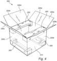
- a package comprising at least one protection structure.
- the package comprises a protection structure folded from a blank as disclosed in various levels of details in the summary above and as disclosed in further various levels of details in the following.
- the package comprises a bottom formed of one or more bottom panels, a plurality of side walls, and a top formed of one or more top panels.
- the at least one protection structure is positioned along an interior corner edge formed of inside surfaces of the bottom and a side wall, the top and a side wall, or two adjacent side walls, wherein the protection structure preferably is oriented such that the landing portions face inwardly towards an interior of the package.
- first, second, third, fourth, etc. are mainly to be seen as labels facilitating reading and that it does not necessarily mean that there need to be all the intervening numbers of portions or panels present. It may also be noted that the labels first, second, third, and fourth does not necessarily mean that the portions or panels are arranged in a specific order based on the labels from first to fourth. The labels first, second, third, and fourth are introduced in an order facilitating reading of the disclosure. It may e.g., be noted that in the preferred embodiment, the main panels are arranged as seen along the transversal direction in the order, the second main panel, the first main panel, the third main panel, and the fourth main panel.
- names such as front, top, rear, or bottom, respectively, are intended to be read as labels, not necessarily defining the orientation of a surface of the protection structure.
- the protection structure does not need to be oriented such that the front surface actually forms the front of the protection structure.
- the protection structure may be oriented such that the portion labelled front portion actually forms a top surface or even forms a bottom surface of the protection structure.
- the invention may also in short be said to relate to a blank, a protection structure formed by such a blank, and a package comprising such a protection structure, the blank comprising a front portion, a top portion, a first landing portion, a second landing, at least one adjustment portion, wherein each adjustment portion comprises a first portion and a second portion, wherein the front portion and the top portion are foldably connected to each other, wherein the first landing portion and the second landing portion are foldably connected to each other, wherein the first and second portions of the respective adjustment portion are foldably connected to each other, wherein the front portion and the top portion are configured to be folded relative to each other, wherein the first and second landing portions are configured to be folded relative to the front portion and the top portion, and wherein the first and second portions of the respective adjustment portion are configured to optionally be folded into a first position, or into a second position.
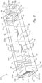
- the blank 100 comprises a first main panel 10.
- the first main panel 10 comprises a front portion 10a.
- the front portion 10a is U-shaped with a longitudinally extending bottom 11a and two shanks 12a extending transversally therefrom.
- the two shanks 12a extend transversally from a respective opposing end portion of the bottom 11a.
- the shanks 12a may extend, relative the bottom 11a, with an angle being obtuse.
- the two shanks 12a extend perpendicularly to the bottom 11a. It is conceivable that each of the shanks 12a may extend with a different angle relative the bottom 11a.
- a length of each of the shanks 12a as seen along a longitudinal direction L is the same.
- a height of each of the shanks 12a as seen along a transversal direction T is the same.
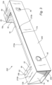
- the front portion 10a is configured to form a front surface 210a of the protection structure 200.
- the front portion 10a alternatively comprises more than two shanks 12a.
- the front portion 10a may comprise three shanks 12a.
- the third shank 12a may extend transversally from a central portion of the bottom 11a and hence form a first section between the shank 12a extending from an end portion of the bottom 11a and the centrally positioned shank 12a, and a second section between the shank 12a extending from an opposing end portion of bottom 11a and the centrally positioned shank 12a.
- the number of sections may hence vary depending on the number of shanks 12a that the front portion 10a is provided with.
- the first main panel 10 also comprises a top portion 10b.
- the top portion 10b is U-shaped with a longitudinally extending bottom 11b and two shanks 12b extending transversally therefrom. It may be noted that the top portion 10b is an inverted U-shape relative to the shape of the front portion 10a.
- the term "inverted U-shaped" is herein meant that the shape of the top portion 10b is more or less a mirror image, as seen in a flat-laid state of the blank 100, of the shape of the front portion 10a with respect to a longitudinally extending axis.
- the two shanks 12b extend transversally from a respective opposing end portion of the bottom 11b.
- the shanks 12b may extend, relative the bottom 11b, with an angle being obtuse.
- the two shanks 12b extend perpendicularly to the bottom 11b. It is conceivable that each of the shanks 12b may extend with a different angle relative the bottom 11b.
- a length of each of the shanks 12b as seen along a longitudinal direction L is the same.
- a height of each of the shanks 12b as seen along a transversal direction T is the same.
- the top portion 10b is configured to form a top surface 210b of the protection structure 200. It may be noted that a height of each of a shank 12a of the front portion 10a may differ from a height of each of a shank 12b of the top portion 10b.
- the top portion 10b alternatively comprises more than two shanks 12b.
- the top portion 10b may comprise three shanks 12b.
- the third shank 12b may extend transversally from a central portion of the bottom 11b and hence form a first section between the shank 12b extending from an end portion of the bottom 11b and the centrally positioned shank 12b, and a second section between the shank 12b extending from an opposing end portion of bottom 11b and the centrally positioned shank 12b.
- the number of sections may hence vary depending on the number of shanks 12b that the top portion 10b is provided with.
- a first landing portion 15a is positioned between the shanks 12a, 12b of the front portion 10a and the top portion 10b.
- the first landing portion 15a is located between and may extend part of or the whole longitudinal distance between the shanks 12a, 12b of the front portion 10a and the top portion 10b along a longitudinal direction L except for the provision of adjustment portions 18 on one or both sides of the first landing portion 15a.
- a length of the first landing portion 15a may correspond to a distance as seen along a longitudinal direction L between a respective inner transversally extending edge of two opposing shanks 12a, 12b.
- a length of the first landing portion 15a may correspond to a distance as seen along a longitudinal direction L between a respective inner transversally extending edge of two opposing adjustment portions 18.
- a height of the first landing portion 15a may correspond to a distance as seen along a transversal direction T corresponding to a height of a shank 12a, b.
- the first landing portion 15a is foldably connected to an inner edge of the bottom 11a of the U-shaped front portion 10a.
- a respective end portion of the first landing portion 15a may be separated from a shank 12a, 12b, or from an adjustment portion 18, by a cut.
- a second landing portion 15b is positioned between the shanks 12a, 12b of the front portion 10a and the top portion 10b.
- the second landing portion 15a is located between and may extend part of or the whole longitudinal distance between the shanks 12a, 12b of the front portion 10a and the top portion 10b along a longitudinal direction L except for the provision of adjustment portions 18 on one or both sides of the second landing portion 15b.
- a length of the second landing portion 15b may correspond to a distance between a respective inner transversally extending edge of two opposing shanks 12a, 12b.
- a length of the second landing portion 15b may correspond to a distance as seen along a longitudinal direction L between a respective inner transversally extending edge of two opposing adjustment portions 18.
- a height of the second landing portion 15b may correspond to a distance as seen along a transversal direction T corresponding to a height of a shank 12a, b.
- the second landing portion 15b is foldably connected to an inner edge of the bottom 11b of the inverted U-shaped top portion 10b.
- a respective end portion of the second landing portion 15b may be separated from a shank 12a, 12b, or from an adjustment portion 18, by a cut.
- the front portion 10a and the top portion 10b are foldably connected to each other along a longitudinally extending first fold line fl1.
- the front portion 10a and the top portion 10b are foldably connected to each other by the shanks 12a of the front portion 10a being foldably connected to the shanks 12b of the top portion 10b along the first fold line fl1.
- the first landing portion 15a and the second landing portion 15b are foldably connected to each other along a longitudinally extending second fold line fl2.
- the front portion 10a and the top portion 10b may also be said to be foldably connected to each other by the first and second landing portions 15a, 15b being foldably connected to each other along the second fold line fl1.
- At least one adjustment portion 18 is positioned, as seen along a longitudinal direction L, between the landing portions 15a, 15b and the shanks 12a, 12b of the front and top portions 10a, 10b.
- Each adjustment portion 18 comprises a first portion 18a being foldably connected to an inner edge of the bottom 11a of the U-shaped front portion 10a.
- Each adjustment portion 18 also comprises a second portion 18b being foldably connected to an inner edge of the bottom 11b of the inverted U-shaped top portion 10b.
- the first and second portions 18a, 18b of the respective adjustment portion 18 are foldably connected to each other along a longitudinally extending third fold line fl3.
- the front portion 10a and the top portion 10b may also be said to be foldably connected to each other by the first and second portions 18a, 18b of the adjustment portions 18 being foldably connected to each other along the third fold line fl3.
- the third fold line fl3 of an adjustment portion 18 may be said to divide the adjustment portion 18 into a first portion 18a and a second portion 18b.
- a plurality of adjustment portions 18 may be positioned adjacently each other one after the other as seen along the longitudinal direction L. Each adjustment portion 18 may be aligned with each other. Each adjustment portion 18 may extend in parallel with each other. Each adjustment portion 18 may be separated from each other at a respective transversally extending edge by a respective transversally extending cut. An adjustment portion 18 being positioned adjacent a shank 12a, 12b may be separated from that shank 12a, 12b at a transversally extending edge by a transversally extending cut. An adjustment portion 18 being positioned adjacent a landing portion 15a, 15b may be separated from that landing portion 15a, 15b at a transversally extending edge by a transversally extending cut. It may be noted that different designs are conceivable.
- the number and the dimension along the longitudinal direction L of the different adjustment portions 18 may vary, e.g., by having different number and/or dimensions on respective side of the landing portions 15a, 15b
- the front portion 10a and the top portion 10b are configured to be folded relative to each other in a first folding direction FD1.
- the front portion 10a and the top portion 10b may be configured to be folded relative each other such that they extend perpendicularly in relation to each other.
- the front portion 10a and the top portion 10b form a front surface 210a and a top portion 210b, respectively, of the protection structure 200, which front surface 210a and top portion 210 extend perpendicularly in relation to each other.
- the front surface 210a and the top surface 210b are folded relative each other such that they extend with any other angle.
- the front surface 210a and the top portion 210b may form an obtuse angle therebetween.
- the first landing portion 15a is configured to be folded relative to the front portion 10a in the first folding direction.
- the second landing portion 15b is configured to be folded relative to the top portion 10b in a second folding direction being opposite the first folding direction.
- the first and second landing portions 15a, 15b are configured to be folded relative to each other by the second landing portion 15b being folded relative to the first landing portion 15a in the second folding direction.
- the first and landing portions 15a, 15b may be configured to be folded relative each other such that they extend perpendicularly in relation to each other.
- the first landing portion 15a is configured to form a first landing surface 215a of the protection structure 200.
- the second landing portion 15b is configured to form a second landing surface 215b of the protection structure 200.
- the first and second landing portions 15a, 15b extend in parallel with the front and top portions 210a, 210b, respectively.
- the first and second landing portions 15a, 15b When the blank 100 is to be folded into a protection structure 200, the first and second landing portions 15a, 15b extend in parallel with the front and top portions 210a, 210b, respectively.
- the first and second landing portions 15a, 15b When the first and second landing portions 15a, 15b are folded in the second folding direction, they may be said to collapse into a state where they form the first and second landing surface 215a, b, respectively, of the protection structure 200.
- This collapsed state may also be said to define an open compartment in which at least a part of at least a good is to be positioned.
- the open compartment may, as previously discussed, be defined as a collapsed portion of the protection structure 200.
- the collapsed portion forms a structure being defined by the first landing surface 215a, the second landing surface 215b, and optionally also by any adjustment portions 18 folded into
- the first landing portion 15a and the second landing portion 15b form a first landing surface 215a and a second landing surface 215b, respectively, of the protection structure 200, which first landing surface 215a and second landing surface 215b preferably extend perpendicularly in relation to each other.
- the open compartment may have a rectangular cross-sectional profile. It is conceivable that the first landing surface 215a and the second landing surface 215b are folded relative each other such that they extend with any other angle. For instance, the first landing surface 215a and the second landing surface 215b may form an obtuse angle therebetween.
- the cross-sectional profile of the open compartment may vary depending on how the first landing surface 215a and the second landing surface 215b extend in relation to each other.
- the first and second portions 18a, 18b of respective adjustment portion 18 are configured to optionally be folded into a first position or into a second portion.
- first and second portions 18a, 18b of the respective adjustment portion 18 are folded relative to each other by the second portion 18b of the respective adjustment portion 18 being folded relative to the respective first portion 18a in the first folding direction.
- first and second portions 18a, 18b of the respective adjustment portion 18 are folded relative to the front portion 10a and the top portion 10b, respectively, and are folded relative to each other by the second portion 18b of the respective adjustment portion 18 being folded relative to the respective first portion 18a in the second folding direction.
- the first and second portions 18a, 18b of the respective adjustment portion 18 may initially be folded in the same manner as the front and top portions 10a, 10b into a state where the first and second portions 18a, 18b of the respective adjustment portion 18 extend in parallel with the front and top portions 210a, 210b, respectively.
- This state may define the first position of the first and second portions 18a, 18b of the respective adjustment portion 18. It is conceivable that the first position is not necessarily defined by the first and second portions 18a, 18b extending completely in parallel with the front and top portions 210a, 210b, respectively.
- the shape of the adjustment portions 18 matches the shape of the shanks 12a, 12b of the front and top surfaces 210a, 210b when the blank 100 has been folded into a protection structure 200 and when the adjustment portions are kept in the first position.
- the first and second portions 18a, 18b may be said to form part of the shanks 12a, 12b when the first and second portions 18a, b are kept in the first position.
- first and second portions 18a, 18b When the first and second portions 18a, 18b are folded relative each other in the other folding direction, they may collapse into a state where they form part of the first and second landing surfaces 215a, 215b.
- the first and second portions 18a, 18b may be said to form part of the open compartment.
- the first and second portions 18a, 18b of the respective adjustment portion 18 may extend in parallel with the first and second landing surfaces 215a, 215b.
- the first and second portions 18a, 18b may in this context be said to be coplanar with the first and second landing surfaces 215a, 215b.
- This state defines the second position of the first and second portions 18a, 18b of the respective adjustment portion 18.
- the second position is not necessarily defined by the first and second portions 18a, 18b extending completely in parallel with the front and top portions 210a, 210b. It is however preferred that the shape of the adjustment portions 18 matches the shape of the first and second landing surfaces 215a, 215b when the blank 100 has been folded into a protection structure 200 and when the adjustment portions are kept in the second position. Alternatively expressed, the second position is not necessarily defined by the first and second portions 18a, 18b being coplanar with the first and second landing surfaces 215a, 215b.
- the third fold line fl3 may, and preferably does, coincide with the first fold line fl1 as seen in a flat-laid state of the blank 100.
- the third fold line fl3 may, and preferably does, align with the first fold fl1 as seen in a flat-laid state of the blank 100.
- the third fold line fl3 may, and preferably does, extend in parallel with the first fold line fl1 as seen in a flat-laid state of the blank 100.
- the blank 100 may be provided with a plurality of adjustment portions 18.
- a plurality of adjustment portions 18 may be positioned adjacently each other.
- Each third fold line fl3 may coincide with an adjacent third fold line fl3 as seen in a flat-laid state of the blank 100.
- Each third fold line fl3 may be aligned with an adjacent third fold line fl3 as seen in a flat-laid state of the blank 100.
- Each third fold line fl3 may extend in parallel with an adjacent third fold line fl3 as seen in a flat-laid state of the blank 100.
- each third fold line fl3 may be aligned with an adjacent spaced apart third fold line fl3 as seen in a flat-laid state of the blank 100.
- Each third fold line fl3 may extend in parallel with an adjacent spaced apart third fold line fl3 as seen in a flat-laid state of the blank 100.
- Each of the first fold lines fl1, second fold lines fl2, and third fold lines fl3 may coincide as seen in a flat-laid state of the blank 100.
- Each of the first fold lines fl1, second fold lines fl2, and third fold lines fl3 may be aligned as seen in a flat-laid state of the blank 100.
- Each of the first fold lines fl1, second fold lines fl2, and third fold lines fl3 may extend in parallel with each other as seen in a flat-laid state of the blank 100.
- first fold lines fl1, second fold lines fl2, and third fold lines fl3 coincide as seen in a flat-laid state of the blank 100, it may require deformation of each of the landing portions 15a, 15b in order to form the open compartment.
- Each first fold line fl1 may extend in parallel with a bottom 11a, 11b of any of the front and top portions 10a, 10b.
- Each second fold line fl2 may extend in parallel with a bottom 11a, 11b of any of the front and top portions 10a, 10b.
- Each third fold line fl3 may extend in parallel with a bottom 11a, 11b of any of the front and top portions 10a, 10b
- the second fold line fl2 may be, and preferably is, transversally offset relative the first fold line fl1 as seen in a flat-laid state of the blank 100.
- the second fold line fl2 may be transversally offset towards the inner edge of the bottom of the inverted U-shaped top portion 210b as seen in a flat-laid state of the blank 100.
- a distance, as seen along a transversal direction in a flat laid-state of the blank 100, between the transversally offset second fold line fl2 and the inner edge of the bottom 11b of the inverted U-shaped top portion 10b corresponds to a distance, as seen along a transversal direction in a flat laid-state of the blank 100, between the first fold line fl1 and the inner edge of the bottom 11a of the U-shaped front portion 10a.
- the first landing surface 215a extends in parallel with the top surface 210b.
- the second landing surface 215b extends in parallel with the front surface 210a.
- the first main panel 10 may be, along at least a part of its longitudinal extension, designed without a fold line between the first and second landing portions 15a, 15b.
- said part of the longitudinal extension of the first main panel 10 not being provided with a fold line may need to be deformed or alternatively form part of cut-out portions as discussed below with reference to the supporting tabs 16.
- the first main panel is provided with either a fold line or cut-outs along basically the whole extension between the adjustment portions 18.
- the respective adjustment portion 18 may be provided with at least one additional fold line fl4.
- the first portion 18a of the adjustment portion 18 may be provided with at least one additional fold line fl4.
- the second portion 18b of an adjustment portion may be provided with the at least one additional fold line fl4.
- the blank 100 may be provided with a plurality of adjustment portions 18.
- a plurality of adjustment portions 18 may be positioned adjacently each other.
- Each additional fold line fl4 may coincide with an adjacent additional fold line fl4 as seen in a flat-laid state of the blank 100.
- Each additional fold line fl4 may be aligned with an adjacent additional fold line fl4 as seen in a flat-laid state of the blank 100.
- Each additional fold line fl4 may extend in parallel with an adjacent additional fold line fl4 as seen in a flat-laid state of the blank 100.
- each additional fold line fl4 may be aligned with an adjacent spaced apart additional fold line fl4 as seen in a flat-laid state of the blank 100.
- Each additional fold line fl4 may extend in parallel with an adjacent spaced apart additional fold line fl4 as seen in a flat-laid state of the blank 100.
- the at least one additional fold line fl4 of respective adjustment portion 18 may, and preferably does, coincide with the second fold line fl2 as seen in a flat-laid state of the blank 100.
- the additional fold line fl4 may be, and preferably is, aligned with the second fold line fl2 as seen in a flat-laid state of the blank 100.
- the additional fold line fl4 may, and preferably does, extend in parallel with the second fold line fl2 as seen in a flat-laid state of the blank 100.
- the fold lines discussed herein may be designed in a variety of ways to facilitate folding and still allow the different portions or panels to remain interconnected.
- the fold lines may be designed as creases, as intermittently arranged cuts or perforations, or combinations thereof.
- the relative position of the respective fold lines of the blank 100 may vary depending on a chosen thickness and material grade of the blank 100.
- the blank 100 may comprise a plurality of main panels arranged one after another along a transversal direction T as seen in a flat-laid state of the blank 100.
- the blank 100 may comprise a plurality of main panels arranged one after another along a longitudinal direction L as seen in a flat-laid state of the blank 100.
- the blank 100 may comprise a second main panel 20 foldably connected to a longitudinally extending edge of the first main panel 10.
- the blank 100 may further comprise a third main panel 30 foldably connected to a longitudinally extending edge of the first main panel 10.
- the second main panel 20 may be configured to form a first rear surface 220 of the protection structure 200.
- the third main panel 30 may be configured to form a bottom surface 230 of the protection structure 200.
- the blank 100 may further comprise a fourth main panel 40 foldably connected to the third main panel 30 at an outer, longitudinally extending edge and being configured to form a second rear surface 240 of the protection structure 200.
- the fourth main panel 40 may be configured to be folded onto the second main panel 20 and be attached to the second main panel 20 such that the main panels of the blank 200 form an interconnected loop of main panels.
- the second main panel 20 may be provided with at least one internal through-going opening 26.
- the fourth main panel 40 may be provided with at least one internal attachment tab 46 being foldable relative to the fourth main panel 40.
- a respective internal through-going opening 26 may be longitudinally positioned such that there, along a longitudinal direction L, is an overlap between a respective internal through-going opening 26 and a respective internal attachment tab 46.
- the fourth main panel 40 may be folded relative to the third main panel 30 and onto the second main panel 20.
- the respective internal attachment tab 46 may be configured to be folded towards the second main panel 20 at least partly through the respective internal through-going opening 26 and thereby keep the second and fourth main panels 20, 40 in the folded position.
- the second landing portion 15b may be provided with at least one supporting tab 16 being formed by a cut which has end portions connecting with the second fold line fl2 and which extends into the geometrical perimeter of the first landing portion 15a.
- each supporting tab 16 may further have a longitudinally and transversally extending central portion extending from the second fold line fl2 into the geometrical perimeter of the first landing portion 15a as seen in a flat-laid state of the blank 100.
- Each supporting tab 16 may form an integral part of the second landing portion 15b.
- each supporting tab 16 may be configured to abut the third main panel 30 when the blank 100 has been folded into a protection structure 200.
- Each supporting tab 16 may be configured to extend in parallel with the second landing surface 215b.
- Each supporting tab 16 may be configured to extend in parallel with the front surface 210a.
- Each supporting tab 16 may be configured to extend perpendicularly to the first landing surface 215a.
- the first landing portion 15a may be provided with at least one supporting tab being formed by a cut. Any such supporting tab 16 may be formed internally in the first landing portion 15a. Said each supporting tab 16 may form part of the first landing portion 15a. Said each supporting tab 16 may be configured to be folded relative to the first landing portion 15 and abut the third main panel 30 when the blank 100 has been folded into a protection structure 200.
- the third main panel 30 may be provided with at least one through-going opening configured to receive a respective supporting tab 16.
- the third main panel 30 may be provided with at least one slit 36 configured to receive a respective supporting tab 16.
- Each slit 36 may be configured to receive a central portion of the respective supporting tab 16.
- material in the slit 36 may still be present, but may be easily pushed inwardly or outwardly relative the third main panel 30 by a portion of the slit 36 being defined by a perforation or a cut forming a loop around said slit 36.
- Each slit 36 may be transversally positioned at a distance from that longitudinally extending edge foldably connecting the third and fourth main panels 30, 40 a distance corresponding to a height of the bottom 11b of the inverted U-shaped top portion 10b. As seen in a flat-laid state of the blank 100, each slit 36 may be longitudinally positioned such that there is an overlap between each slit 36 and each supporting tab 16.
- the top portion 10b may be provided with at least one securing tab 19 being foldably connected to an outer transversally extending edge of the top portion 10b.
- Each securing tab 19 may be configured to abut the third main panel 30 when the blank 100 has been folded into a protection structure 200
- the at least one securing tab 19 is not necessarily limited to being foldably connected to the top portion 10b. On the contrary, each securing tab 19 may be foldably connected to any of the main panels or parts or portions of the blank 100. In any case, it is preferred that the securing tab 19 is configured to abut an opposing main panel or part or portion of the blank 100.
- the protection structure 200 as such may form a through-going opening at a respective opposing end portion of the protection structure 200. Each through-going opening may be defined by a transversally extending free edge of a respective main panel or part of portion of the blank 100.
- Each securing tab 19 may be foldably connected in the vicinity of such a through-going opening of the protection structure 200.
- Each securing tab 19 may be dimensioned to at least partly cover the through-going opening when each securing tab 19 is kept in a folded position.
- the securing tab 19 may also be referred to as an end wall 19.
- Each securing tab 19 may be dimensioned to be slightly bigger than a through-going opening of the protection structure.
- free edges of the securing tab 19 may be configured to abut inner surfaces of the protection structure 200 and thus be kept in their folded position by friction.
- Each securing tab 19 may be configured to extend perpendicularly to any main panel or part or portion of the protection structure 200. Alternatively, each securing tab 19 may be configured to be angled inwardly of the protection structure 200.
- Each securing tab 19 may be provided with at least one securing tongue 19a having a transversal extension and extending longitudinally outwardly from the respective securing tab 19 as seen in a flat-laid state of the blank 100.
- each securing tongue 19a is arranged at a transversally extending free outer edge. It may be conceivable that a securing tongue 19a may be arranged at any free outer edge of a respective securing tab 19.
- a respective at least one securing tab 19a is arranged at a longitudinally extending free outer edge of a respective securing tab 19, said securing tab 19a would have had a longitudinal extension and extending transversally outwardly from the respective securing tab 19 as seen in a flat-laid state of the blank 100. It is also conceivably that a securing tongue 19a may be arranged at a corner of a respective securing tab 19. Each securing tongue 19 may be configured to be inserted into a respective additional slit 39 provided on the third main panel 30 when the blank 100 has been folded into a protection structure 200. It may be noted that the slit 39 may alternatively be any type of opening being capable of receiving the securing tongue 19.
- the opening may be formed in accordance with the embodiments as previously discussed herein. That is, it is for instance conceivable that material in the slit 39 may still be present, but may be easily pushed inwardly or outwardly relative to the third main panel 30 by a portion of the slit 39 being defined by a perforation or a cut forming a loop around said slit 39. This is also applicable to the slit or slits 36 discussed above.
- a securing tongue 19a may be arranged at any free outer edge of a respective securing tab 19.
- the third main panel 30 is not necessarily limited to being that main panel of the blank 100 being provided with the respective additional slit 39 being configured to receive a securing tongue 19a. It is preferred that the main panel or part or portion of the blank 100 which the securing tongue 19a may be configured to be inserted into, is provided with an additional slit 39 being configured to receive said securing tongue 19a.
- the at least one internal through-going opening 26 may alternatively be arranged on the fourth panel 40 and the at least one internal attachment tab 45 may alternatively be arranged on the second panel 20.
- the skilled person realizes that the slits 36, 39 and the securing tabs 19 and associated securing tongues 19a may be designed and arranged on the blank 100 in a variety of ways with remained function.
- the blank 100 is preferably formed of a paper-based material.
- a paper-based material is suitable since it is light-weight, is easy to recycle, is easy to cut into the desired shape, is capable of being transported in a flat-laid state.
Landscapes
- Engineering & Computer Science (AREA)
- Mechanical Engineering (AREA)
- Cartons (AREA)
Priority Applications (1)
| Application Number | Priority Date | Filing Date | Title |
|---|---|---|---|
| EP23461558.1A EP4446246A1 (de) | 2023-04-13 | 2023-04-13 | Zuschnitt zum falten in eine schutzstruktur, aus solch einem zuschnitt geformte schutzstruktur und verpackung mit solch einer schutzstruktur |
Applications Claiming Priority (1)
| Application Number | Priority Date | Filing Date | Title |
|---|---|---|---|
| EP23461558.1A EP4446246A1 (de) | 2023-04-13 | 2023-04-13 | Zuschnitt zum falten in eine schutzstruktur, aus solch einem zuschnitt geformte schutzstruktur und verpackung mit solch einer schutzstruktur |
Publications (1)
| Publication Number | Publication Date |
|---|---|
| EP4446246A1 true EP4446246A1 (de) | 2024-10-16 |
Family
ID=86052073
Family Applications (1)
| Application Number | Title | Priority Date | Filing Date |
|---|---|---|---|
| EP23461558.1A Withdrawn EP4446246A1 (de) | 2023-04-13 | 2023-04-13 | Zuschnitt zum falten in eine schutzstruktur, aus solch einem zuschnitt geformte schutzstruktur und verpackung mit solch einer schutzstruktur |
Country Status (1)
| Country | Link |
|---|---|
| EP (1) | EP4446246A1 (de) |
Citations (6)
| Publication number | Priority date | Publication date | Assignee | Title |
|---|---|---|---|---|
| US2209593A (en) * | 1938-01-19 | 1940-07-30 | Joseph S Butman | Box |
| GB2041868A (en) * | 1979-02-20 | 1980-09-17 | Baker B G | Edge Protection Pieces |
| US6138901A (en) * | 1997-11-14 | 2000-10-31 | Kim; Bobby | Multipurpose adjustable single sheet container |
| DE20112346U1 (de) * | 2001-07-28 | 2001-10-25 | THIMM Consulting GmbH & Co. KG, 37154 Northeim | Kantenschutzpolster |
| DE202007006587U1 (de) * | 2007-05-04 | 2007-08-30 | Lewell Kartonagen Gmbh | Faltzuschnitt für eine Stabilisierungsecke |
| FR2987824A1 (fr) | 2012-03-08 | 2013-09-13 | Gerard Guy Martorella | Boite en carton a volume variable |
-
2023
- 2023-04-13 EP EP23461558.1A patent/EP4446246A1/de not_active Withdrawn
Patent Citations (6)
| Publication number | Priority date | Publication date | Assignee | Title |
|---|---|---|---|---|
| US2209593A (en) * | 1938-01-19 | 1940-07-30 | Joseph S Butman | Box |
| GB2041868A (en) * | 1979-02-20 | 1980-09-17 | Baker B G | Edge Protection Pieces |
| US6138901A (en) * | 1997-11-14 | 2000-10-31 | Kim; Bobby | Multipurpose adjustable single sheet container |
| DE20112346U1 (de) * | 2001-07-28 | 2001-10-25 | THIMM Consulting GmbH & Co. KG, 37154 Northeim | Kantenschutzpolster |
| DE202007006587U1 (de) * | 2007-05-04 | 2007-08-30 | Lewell Kartonagen Gmbh | Faltzuschnitt für eine Stabilisierungsecke |
| FR2987824A1 (fr) | 2012-03-08 | 2013-09-13 | Gerard Guy Martorella | Boite en carton a volume variable |
Similar Documents
| Publication | Publication Date | Title |
|---|---|---|
| US20090072015A1 (en) | Blanks for Containers | |
| US10472122B2 (en) | Container with a reinforcement structure and method of forming the same | |
| EP3301035B1 (de) | Behälterzuschnitt für einen behälter und verfahren zum herstellen eines behälters | |
| US5016814A (en) | Collapsible box with improved corner locks | |
| US20090301928A1 (en) | Packaging For Lipped Containers | |
| CA2702784C (en) | Carton bottom closure | |
| EP4041645A1 (de) | Zuschnitt zur herstellung eines einsatzes | |
| WO2009109732A1 (en) | Blanks and boxes with tongue- pocket bottom combination formable from said blanks | |
| CA2990604A1 (en) | Container with a reinforcement structure and method of forming the same | |
| EP1490269B1 (de) | Verbesserungen in und in beziehung zu trägern aus pappenzuschnitten | |
| CA2417323C (en) | Paperboard container having in-fold panel engaged between expanding walls during erection | |
| JP2010111421A (ja) | 紙製収容箱 | |
| EP4446246A1 (de) | Zuschnitt zum falten in eine schutzstruktur, aus solch einem zuschnitt geformte schutzstruktur und verpackung mit solch einer schutzstruktur | |
| GB2427399A (en) | Blank for container with curved walls | |
| US4416412A (en) | Collapsible carton with interior partitions | |
| US20100260444A1 (en) | Reinforced bag | |
| US5040683A (en) | Shipping wedge, and blank for forming such a wedge | |
| SE2151366A1 (en) | A blank and a package having integrated buffer and being erected from a blank | |
| US20260048894A1 (en) | Blank configured to be erected into a package and a package formed by such a blank | |
| EP4269263A1 (de) | Zuschnitt | |
| EP4157735B1 (de) | Zuschnitt zur herstellung einer verpackung und aus einem solchen zuschnitt hergestellte verpackung | |
| US6209783B1 (en) | Reinforced cardboard box for storage and shipping of elongated items and rolled documents | |
| WO2000068103A1 (en) | One piece folded and glued container having corner support spacers | |
| GB2421019A (en) | Blank for a pillow-shaped container with tamper-evident features | |
| EP4393840A1 (de) | Zuschnitt, der zum falten in eine schutzstruktur konfiguriert ist, und eine aus solch einem zuschnitt geformte schutzstruktur |
Legal Events
| Date | Code | Title | Description |
|---|---|---|---|
| PUAI | Public reference made under article 153(3) epc to a published international application that has entered the european phase |
Free format text: ORIGINAL CODE: 0009012 |
|
| STAA | Information on the status of an ep patent application or granted ep patent |
Free format text: STATUS: THE APPLICATION HAS BEEN PUBLISHED |
|
| AK | Designated contracting states |
Kind code of ref document: A1 Designated state(s): AL AT BE BG CH CY CZ DE DK EE ES FI FR GB GR HR HU IE IS IT LI LT LU LV MC ME MK MT NL NO PL PT RO RS SE SI SK SM TR |
|
| RAP3 | Party data changed (applicant data changed or rights of an application transferred) |
Owner name: STORA ENSO OYJ |
|
| STAA | Information on the status of an ep patent application or granted ep patent |
Free format text: STATUS: THE APPLICATION IS DEEMED TO BE WITHDRAWN |
|
| 18D | Application deemed to be withdrawn |
Effective date: 20250417 |