EP4393840A1 - Zuschnitt, der zum falten in eine schutzstruktur konfiguriert ist, und eine aus solch einem zuschnitt geformte schutzstruktur - Google Patents
Zuschnitt, der zum falten in eine schutzstruktur konfiguriert ist, und eine aus solch einem zuschnitt geformte schutzstruktur Download PDFInfo
- Publication number
- EP4393840A1 EP4393840A1 EP22461657.3A EP22461657A EP4393840A1 EP 4393840 A1 EP4393840 A1 EP 4393840A1 EP 22461657 A EP22461657 A EP 22461657A EP 4393840 A1 EP4393840 A1 EP 4393840A1
- Authority
- EP
- European Patent Office
- Prior art keywords
- panel
- side panel
- central main
- longitudinally extending
- main panel
- Prior art date
- Legal status (The legal status is an assumption and is not a legal conclusion. Google has not performed a legal analysis and makes no representation as to the accuracy of the status listed.)
- Pending
Links
- 230000002787 reinforcement Effects 0.000 claims abstract description 81
- 239000000463 material Substances 0.000 claims description 73
- 238000009413 insulation Methods 0.000 claims description 4
- 230000002730 additional effect Effects 0.000 claims description 3
- 239000000123 paper Substances 0.000 description 25
- 239000010410 layer Substances 0.000 description 14
- 210000002105 tongue Anatomy 0.000 description 14
- 239000000853 adhesive Substances 0.000 description 13
- 230000001070 adhesive effect Effects 0.000 description 13
- 239000011111 cardboard Substances 0.000 description 6
- 238000004519 manufacturing process Methods 0.000 description 6
- 239000004033 plastic Substances 0.000 description 4
- 239000000047 product Substances 0.000 description 4
- 239000002356 single layer Substances 0.000 description 3
- 239000002023 wood Substances 0.000 description 3
- 239000006227 byproduct Substances 0.000 description 2
- 238000006073 displacement reaction Methods 0.000 description 2
- 238000004806 packaging method and process Methods 0.000 description 2
- 238000000926 separation method Methods 0.000 description 2
- 239000002699 waste material Substances 0.000 description 2
- 230000001419 dependent effect Effects 0.000 description 1
- 230000007613 environmental effect Effects 0.000 description 1
- 239000004744 fabric Substances 0.000 description 1
- 239000006262 metallic foam Substances 0.000 description 1
- 238000000034 method Methods 0.000 description 1
- 238000012986 modification Methods 0.000 description 1
- 230000004048 modification Effects 0.000 description 1
- 239000011087 paperboard Substances 0.000 description 1
- 239000002984 plastic foam Substances 0.000 description 1
- 230000001012 protector Effects 0.000 description 1
- 239000007787 solid Substances 0.000 description 1
Images


Classifications
-
- B—PERFORMING OPERATIONS; TRANSPORTING
- B65—CONVEYING; PACKING; STORING; HANDLING THIN OR FILAMENTARY MATERIAL
- B65D—CONTAINERS FOR STORAGE OR TRANSPORT OF ARTICLES OR MATERIALS, e.g. BAGS, BARRELS, BOTTLES, BOXES, CANS, CARTONS, CRATES, DRUMS, JARS, TANKS, HOPPERS, FORWARDING CONTAINERS; ACCESSORIES, CLOSURES, OR FITTINGS THEREFOR; PACKAGING ELEMENTS; PACKAGES
- B65D81/00—Containers, packaging elements, or packages, for contents presenting particular transport or storage problems, or adapted to be used for non-packaging purposes after removal of contents
- B65D81/02—Containers, packaging elements, or packages, for contents presenting particular transport or storage problems, or adapted to be used for non-packaging purposes after removal of contents specially adapted to protect contents from mechanical damage
- B65D81/05—Containers, packaging elements, or packages, for contents presenting particular transport or storage problems, or adapted to be used for non-packaging purposes after removal of contents specially adapted to protect contents from mechanical damage maintaining contents at spaced relation from package walls, or from other contents
- B65D81/053—Corner, edge or end protectors
-
- B—PERFORMING OPERATIONS; TRANSPORTING
- B65—CONVEYING; PACKING; STORING; HANDLING THIN OR FILAMENTARY MATERIAL
- B65D—CONTAINERS FOR STORAGE OR TRANSPORT OF ARTICLES OR MATERIALS, e.g. BAGS, BARRELS, BOTTLES, BOXES, CANS, CARTONS, CRATES, DRUMS, JARS, TANKS, HOPPERS, FORWARDING CONTAINERS; ACCESSORIES, CLOSURES, OR FITTINGS THEREFOR; PACKAGING ELEMENTS; PACKAGES
- B65D2581/00—Containers, packaging elements, or packages, for contents presenting particular transport or storage problems, or adapted to be used for non-packaging purposes after removal of contents
- B65D2581/02—Containers, packaging elements, or packages, for contents presenting particular transport or storage problems, or adapted to be used for non-packaging purposes after removal of contents specially adapted to protect contents from mechanical damage
- B65D2581/05—Containers, packaging elements, or packages, for contents presenting particular transport or storage problems, or adapted to be used for non-packaging purposes after removal of contents specially adapted to protect contents from mechanical damage maintaining contents at spaced relation from package walls, or from other contents
- B65D2581/051—Details of packaging elements for maintaining contents at spaced relation from package walls, or from other contents
- B65D2581/052—Materials
- B65D2581/053—Paper in general, e.g. paperboard, carton, molded paper
Definitions
- the prior art document does not adequately address the set of design criteria that the protection structure should make efficient use of the material, is easy to transport to the point of use, is easy to prepare for use with a minimum use of adhesive, and provides a strong structure and good protection. Moreover, the prior art document does not adequately address the set of design criteria that the protection structure should be convenient to handle at point of use, and be able to retain its shape.
- a blank capable of making efficient use of material is easy to prepare for use and is convenient to fold and handle.
- a blank whereupon folding the blank into a protection structure the configuration of the blank allows for parts of the blank itself to form part of the buffer sections.
- parts of the blank forming part of the buffer sections there is provided a blank having, at least partly, integrally formed buffer sections.
- this makes the blank easy to transport to the point of use, considering that it is often easier to transport lesser separate components configured to be assembled to form a single unit.
- first cut-lines, along the first main fold line and/or transversally offset thereof there is provided longitudinally extending sections or gaps between the buffer sections along which the first side panel may be distinctly flat-laid onto the central main panel.
- the first side panel is provided with at least one locking tab being formed by a cut which has end portions connecting with the third internal fold line, and which has a longitudinally extending central portion being transversally offset relative the third internal fold line in a direction towards the base portion of the first side panel, wherein the locking tab is longitudinally positioned such that there, along a longitudinal direction, is an overlap between the locking tab, the first, second, and third internal fold lines, and those parts where the first longitudinally extending side is foldably connected to the central main panel, and wherein the locking tabs are configured to interact with the central main panel and thereby keep the intermediate panels folded around the reinforcement beams in the folded position.
- An advantage with this design is that by the locking tabs providing the intermediate panels the capability of being kept in the folded position there is provided a protection structure capable of being mechanically strong over a sufficient time period and retaining its shape during handling.
- the locking tabs may interact with the central main panel or any other panel being configured to be arranged on the central main panel. Furthermore, the locking tabs may be integrally formed with the first side panel.
- the locking tabs being a part of a single blank forming the protection structure, it is possible to make efficient use of material.
- the protection structure having locking tabs that may be formed from a single blank the blank is also easy to prepare for use, as opposed to attaching external locking tabs to the first side panel or the protection structure. Furthermore, this makes the blank easy to transport to the point of use, considering that it is most often easier to transport a single unit rather than to transport several separate components configured to be assembled to form a single unit.
- the central main panel may be provided with at least one longitudinally extending opening being transversally positioned at a distance from the first longitudinally extending main fold line corresponding to a transversal distance between the first and second internal fold lines, and being longitudinally positioned such that, along the longitudinal direction, the respective opening at least overlaps with the respective locking tab such that the respective opening is configured to receive the respective locking tab and thereby keep those parts of the first side panel being folded around the reinforcement beams in the folded position.
- the locking tabs may be connected to central main panel without use of any adhesive and allows for the buffer sections to be quickly formed upon folding the blank into a protection structure.
- adhesive to connect the locking tabs with the central main panel or for that matter using adhesive to connect any parts of the protection structure together, the locking tabs and the central main panel may run the risk of being tarnished.
- Any adhesive used on the locking tabs or the central main panel may damage the surface of the locking tabs and the central main panel during disassembling of the protection structure in that the surface of the locking tabs and the central main panel might be ripped off during disassembling of the protection structure, and consequently might even lead to deformation of the blank if the adhesive is adhered to the any surface too strongly.
- the use of adhesive may also make the protection structure difficult to disassemble and recycle at time of disposal.
- the locking tabs are attached to the central main panel without use of adhesive hence the risk of damaging the locking tabs and the central main panel during disassembling of the protection structure is reduced and allows for multiple uses of the blank, thereby making efficient use of material and providing a protection structure capable of being reusable.
- the intermediate portions may form buffer section side walls being substantially perpendicular to the underlying panel.
- This design facilitates forming of the buffer sections and keeping the reinforcement beams in their intended position, which buffer sections would otherwise wobble had the buffer section side walls formed e.g., an obtuse angle relative the underlying panel.
- the second side panel may be provided with at least one securing tab having a longitudinal extension and extending transversely outwardly from a side of the second side panel being opposite the central main panel as seen in a flat-laid state of the blank, the securing tab being longitudinally positioned such that there along a longitudinal direction, is an overlap between the securing tab and those parts where the first longitudinally extending side is separated from the central main panel thereby allowing the securing tab to extend into a longitudinal gap between neighbouring buffer sections.
- the securing tab may further be configured to engage with the underlying panel and/or neighbouring buffer sections.
- the respective securing tab may be dimensioned to have a substantially equal longitudinal extension to that of the respective longitudinal gap between neighbouring buffer sections.
- the respective securing tab may be dimensioned to have a slightly longer longitudinal extension, hence requiring a slight force to allow the respective securing tab to extend into a respective longitudinal gap between neighbouring buffer sections.
- Said at least one securing tab may be provided with at least one securing tongue being foldably connected to the securing tab about a transversally extending fold line, the securing tab and securing tongue being longitudinally positioned such that there along a longitudinal direction, is an overlap between the securing tongue and a buffer section adjoining with the longitudinal gap between neighbouring buffer sections into which the securing tab extends whereby the securing tongue is configured to engage with the respective buffer section and thereby keep the second side panel in the position folded onto the first side panel.
- An advantage with this design is that by the securing tab keeping the second side panel in the folded position where the second side panel is folded onto the central main panel, it is facilitated to keep the protection structure in its triple-walled folded position.
- the protection structure is e.g., being handled by a user or being transported, any external impacts, disturbances and displacements of the protection structure or the product to which the protection structure is attached will not compromise the folded position of the second side panel by the second side panel accidently unfolding from its folded position.
- the protection structure is able to retain its shape.
- the securing tab may be configured to engage with the buffer sections without use of any adhesive and allows for the secuing tab to assume an intended position quickly and conveniently.
- the central main panel and the first side panel, respectively, may be provided with at least one internal through-going opening being longitudinally positioned such that there, along a longitudinal direction, is an overlap between the openings of the central main panel and the first side panel, respectively, such that a respective through-going opening is formed when the first side panel is folded relative the central main panel and onto the central main panel,
- An advantage with this design is that the second side panel is provided with the capability of being connected to the central main panel by use of internally formed structures, in this case at least one internal through-going opening and at least one internal attachment tab, as opposed to providing the protection structure externally formed structures.
- This design allows for the blank to be more compactly formed and is thus more convenient to transport.
- the respective attachment tab When the second side panel is folded relative to the central main panel about the second main fold line and onto the first side panel, the respective attachment tab may be configured to be folded relative to the second side panel towards the central main panel at least partly through the respective through-going opening and thereby keep the second side panel in the folded position.
- the respective attachment tab is not necessarily folded such that the respective attachment tab has completely passed the respective through-going opening.
- the respective attachment tab may be folded such that the respective attachment tab may be configured to be positioned inside the respective through-going opening.
- another advantage with this design is that at least a portion of a free outer edge of the respective attachment tab may abut a perimeter of the respective through-going opening and may be kept in the folded position by e.g., friction.
- the second side panel may be connected to central main panel without use of any adhesive and allows for the second side panel to be quickly and conveniently connected to the central main panel by use of the at least one internal through-going opening and at least one internal attachment tab upon folding the blank into a protection structure.
- the protection structure is able to retain its shape during use.
- the respective opening of the central main panel may comprise a first portion being transversally and longitudinally positioned such that there, is an overlap between the first portions, the openings of the first side panel, and the attachment tabs of the second side panel, wherein the respective opening of the central main panel further comprises a second portion being longitudinally offset said first portion, and wherein the respective attachment tab is configured to be folded through the first portion of the respective opening of the central main panel around an edge of the respective opening of the first side panel and back into the respective second portion.
- the respective attachment tab may assume a position where it is essentially co-planar with the central main panel. Since the attachment tab is positioned within the material thickness of the central main panel, there is minimal risk that the attachment tab is unintentionally moved from this locked position.
- the shape of the attachment tabs may match the shape of the second portions of the openings of the central main panel.
- the attachment tabs may be slightly bigger than the second portions of the openings of the central main panel.
- the attachment tabs may slightly deform in order to fit into the second portions. The friction therebetween facilitates in keeping the attachment tabs in their intended position inside the second portions.
- the second side panel is kept in its folded position, thereby facilitating to keep the protection structure in its triple-walled folded position.
- the blank excluding the reinforcement beams, may have a material thickness and wherein the reinforcement beams have a thickness being at least two times the material thickness.
- the reinforcement beams should ideally have a certain minimum thickness.
- the material thickness and material grade of the material of the blank is chosen to provide a sufficient strength and still an easy folding. This design is advantageous in that by ensuring that the thickness of the reinforcement beams is at least two times the material thickness, the buffer sections provide sufficient product protection in combination with a sufficiently strong and easily foldable blank.
- the reinforcement beams having a thickness refers to the height or thickness in the same direction as the material thickness of the central main panel.
- the reinforcement beam may in turn be formed by folding a material similar to, or even the same as, the blank. In such a case the respective reinforcement beam is folded such that the height is the specified one.
- the reinforcement beams are configured to provide additional properties, such as thermal insulation, to the protection structure, and being compressible, preferably resiliently compressible, allowing the reinforcement beams to be locally compressed.
- the forming of the buffer sections is such that those parts folded around the reinforcement beams locally compress the reinforcement beams. Hence, the folded parts abut the locally compressed reinforcement beams. It is preferable that the reinforcement beams at least partly regain their shape even after being locally compressed during the folding of said parts.
- An advantage with this design is that the reinforcement beams will, due to the act of at least partly regaining their shape, exert an outwardly directed force towards the abutting folded parts. The friction therebetween facilitates in keeping the reinforcement beams in their intended position. Thus, the risk of a at least one reinforcement beam of a buffer section being accidently removed from its intended position is reduced. Further, the reinforcement beams are, at least partly, prevented from being displaced e.g., during transportation or when the protection structure is being handled, thereby preventing the buffer sections from being jeopardized.
- Another advantage with this design is that by the reinforcement beams being able to at least partly return to its unaffected state, the ability to optimally provide other properties such as thermal insulation to the protection structure is at least partly regained.
- the reinforcement beams being resiliently compressible they may be used multiple times with the reinforcement beams having an at least partly maintained unaffected state. This is cost-efficient and the environmental impact may be reduced. It is preferable that the reinforcement beams regain a material thickness of at least 50% of its original material thickness after it has been locally compressed by the folded parts.
- the reinforcement beams may be formed of a paper-based material, the paper-based material preferably being folded into a shape including a stack of a plurality of layers, the stack preferably being arranged such that the layers are oriented in the same plane as the central main panel.
- the reinforcement beams being paper-based is that paper-based materials are recyclable hence making efficient use of the material. Paper-based materials are also renewable and sustainable.
- the reinforcement beams may be formed of the same material as the blank. This is advantageous in that e.g., by-products of manufacturing processes pertinent to the production of the blank may be utilized and not go to waste. This is cost-efficient and facilitates the production of the reinforcement beams. Further, it is provided efficient use of material.
- the blank may be formed of a paper-based material.
- the blank is preferably made of a paper-based material.
- An advantage with the blank being paper-based is that paper-based materials are recyclable hence making efficient use of the material. Paper-based materials are also renewable and sustainable. It is also comparably easy to cut a sheet of paper-based material into the desired shape of the blank. It is also comparably easy to fold a paper-based blank into the desired protection structure.
- the paper-based material may comprise a corrugated layer with flutes. The flutes of the corrugated layer may extend along the longitudinal direction. However, the flutes of the corrugated layer may alternatively extend along the transversal direction.
- the blank may be made of any material normally used in the art for packaging. By way of example, the blank may be made of plastic or wood-based.
- the second longitudinally extending side panel may be along parts of its longitudinal extension foldably connected to the second longitudinal side of the central main panel along the second longitudinally extending main fold line, and is along parts of its longitudinal extension separated from the central main panel by one or more longitudinally extending second cut-lines.
- An advantage with this design is the provision of a pronounced folding of the protection structure hence facilitating handling of the protection structure.
- Those parts of the second side panel being along parts of its longitudinal extension foldably connected to the second longitudinal side of the central main panel along the second main fold line may be slightly compressed when folding the second side panel onto the underlying panel.
- those parts of the second side panel overlapping with the buffer sections exert a slight restoring force towards a direction being opposite to a folding direction of the second side panel.
- an advantage with this design is that there is provided a protection structure having buffer sections adjoining with a planar bridge extending into the longitudinal gap between said buffer sections.
- the protection structure is made compact and easy to handle.
- bridge those parts of the second side panel extending into a respective longitudinal gap between neighbouring buffer sections.
- planar it is meant that the bridge lies flat against the underlying panel.
- a protection structure having buffer sections comprising:
- first, second, etc. are mainly to be seen as labels facilitating reading and that it does not necessarily mean that there need to be all the intervening numbers of portions present.
- the labels first and second does not necessarily mean that the portions or panels are arranged in a specific order based on the labels from first to second.
- the labels first, and second are introduced in an order facilitating reading of the disclosure. It may e.g., be noted that in the preferred embodiment, the main panels are arranged as seen in a flat-laid state of the blank along the transversal direction in the order, the second side panel, the central main panel, and the first side panel.
- the invention may also in short be said to relate to a blank, and a protection structure formed by such a blank, wherein the blank is configured to be folded into a protection structure having buffer sections, the blank comprising a longitudinally extending central main panel, a first longitudinally extending side panel being foldably connected to a first longitudinal side of the central main panel along a first longitudinally extending main fold line, a second longitudinally extending side panel, wherein the first side panel is provided with a first, a second, and a third internal transversally separated and longitudinally extending fold line, wherein the internal fold lines together with the first longitudinally extending main fold line form a first, a second, and a third intermediate portion whereby the first, second, and third intermediate portions are configured to be wrapped around at least one longitudinally extending separately formed reinforcement beam, wherein the second side panel is configured to be folded relative to the central main panel onto the first side panel.
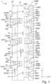
- the blank 1 comprises a longitudinally extending central main panel 10, a first longitudinally extending side panel 20 and a second longitudinally extending side panel 30.
- the first longitudinally extending side panel 20 is along parts of its longitudinal extension, foldably connected to a first longitudinal side of the central main panel 10 along a first longitudinally extending main fold line 10mfl1, and being along parts of its longitudinal extension separated from the central main panel 10 by one or more longitudinally extending first cut-lines 10c11. It may be noted that this separation may be formed by cuts extending along the first main fold line 10mfl1 or may be formed by cuts being transversely offset from the first main fold line 10mfl1. It may further be noted that the respective one or more longitudinally extending first cut-lines 10cl1 may each be positioned at different transversal positions on the central main panel 10. In the preferred embodiment shown in Fig.
- first cut-lines 10cl1 there are double first cut-lines 10cl1 and there is a piece of material cut-out between the first cut-lines 10cl1 extending along the first main fold line 10mfl1 and the first cut-lines 10cl1 being transversally positioned between the first and second internal fold lines 20ifl1, 20ifl2.
- the second longitudinally side panel 30 is foldably connected to a second longitudinal side of the central main panel 10 along a second longitudinally extending main fold line 10mfl2.
- the first side panel 20 is provided with a first, a second, and a third internal transversally separated and longitudinally extending fold line 20ifl1-3.
- the first side panel 20 may be provided with a plurality of first, second, and third internal fold line 20ifl1-3.
- the respective first, second, and third internal fold line 20ifl1-3 may overlap with each other along a longitudinal direction L.
- the second side panel 30 may be provided with at least one securing tab 32.
- the securing tab 32 may be formed by a cut.
- the securing tab 32 may have a longitudinal extension.
- the securing tab 32 may extend transversely outwardly from a side of the second side panel 30 being opposite the central main panel 10 as seen in a flat-laid state of the blank 1.
- the securing tab 32 may form part of the second side panel 30.
- the securing tab 32 may be foldably connected to the second side panel 30 along a longitudinally extending edge of the second side panel 30.
- the second side panel 30 may be provided with at least one internal attachment tab 35 being foldable relative to the second side panel 30.
- the attachment tab 35 may be foldably connected to the second side panel 30 along a transversally extending fold line.
- the respective attachment tab 35 may be configured to be folded relative to the second side panel 30 towards the central main panel 10 at least partly through the respective through-going opening 36 and thereby keep the second side panel 30 in the folded position.
- the respective attachment tab 35 is not necessarily folded such that the respective attachment tab 35 has completely passed the respective through-going opening 36.
- the respective attachment tab 35 may be folded such that the respective attachment tab 35 may be configured to be positioned inside the respective through-going opening 36. At least a portion of a free outer edge of the respective attachment tab 35 may abut a perimeter of the respective through-going opening 36 and may be kept in the folded position by e.g., friction.
- the blank 1 may be formed of a paper-based material.
- An advantage with the blank being paper-based is that paper-based materials are recyclable hence making efficient use of the material. Paper-based materials are also renewable and sustainable. It is also comparably easy to cut a sheet of paper-based material into the desired shape of the blank. It is also comparably easy to fold a paper-based blank into the desired protection structure.
- the paper-based material may comprise a corrugated layer with flutes. The flutes of the corrugated layer may extend along the longitudinal direction. However, the flutes of the corrugated layer may alternatively extend along the transversal direction.
- the blank may be made of any material normally used in the art for packaging. By way of example, the blank may be made of plastic or wood-based.
- the second main fold line 10mfl2 may be formed of a double fold line between the central main panel 10 and the second side panel 30.
- the double fold line may define at least one intermediate panel.
- the intermediate panel may have a transversal extension which is, as seen in a flat-laid state of the blank 1, being substantially equal to an accumulated material thickness of the central main panel 10, first side panel 20 and the second side panel 30. This is advantageous since it allows for the second side panel 30 to be easily folded onto the first side panel 20 after the first side panel 20 has been folded onto the central main panel 10.
- the double fold line may provide a pronounced folding of the protection structure 200 since the intermediate panel may form a pronounced planar edge of the protection structure 200.
Landscapes
- Engineering & Computer Science (AREA)
- Mechanical Engineering (AREA)
- Buffer Packaging (AREA)
Priority Applications (2)
| Application Number | Priority Date | Filing Date | Title |
|---|---|---|---|
| EP22461657.3A EP4393840A1 (de) | 2022-12-28 | 2022-12-28 | Zuschnitt, der zum falten in eine schutzstruktur konfiguriert ist, und eine aus solch einem zuschnitt geformte schutzstruktur |
| PCT/IB2023/063036 WO2024141875A1 (en) | 2022-12-28 | 2023-12-20 | Blank configured to be folded into a protection structure, and a protection structure formed by such a blank |
Applications Claiming Priority (1)
| Application Number | Priority Date | Filing Date | Title |
|---|---|---|---|
| EP22461657.3A EP4393840A1 (de) | 2022-12-28 | 2022-12-28 | Zuschnitt, der zum falten in eine schutzstruktur konfiguriert ist, und eine aus solch einem zuschnitt geformte schutzstruktur |
Publications (1)
| Publication Number | Publication Date |
|---|---|
| EP4393840A1 true EP4393840A1 (de) | 2024-07-03 |
Family
ID=84689222
Family Applications (1)
| Application Number | Title | Priority Date | Filing Date |
|---|---|---|---|
| EP22461657.3A Pending EP4393840A1 (de) | 2022-12-28 | 2022-12-28 | Zuschnitt, der zum falten in eine schutzstruktur konfiguriert ist, und eine aus solch einem zuschnitt geformte schutzstruktur |
Country Status (2)
| Country | Link |
|---|---|
| EP (1) | EP4393840A1 (de) |
| WO (1) | WO2024141875A1 (de) |
Citations (6)
| Publication number | Priority date | Publication date | Assignee | Title |
|---|---|---|---|---|
| US20030111383A1 (en) * | 2001-12-18 | 2003-06-19 | Yanping Qiu | Reinforced packaging support post assembly |
| JP4452250B2 (ja) | 2006-04-13 | 2010-04-21 | 大▲国▼段ボール工業株式会社 | 緩衝材 |
| JP2013071755A (ja) * | 2011-09-28 | 2013-04-22 | Daikin Industries Ltd | 包装用緩衝パッド |
| DE202013105112U1 (de) * | 2012-11-22 | 2013-12-19 | Whirlpool Corporation | Verpackungssystem für Elektrohaushaltsgeräte |
| JP2015077989A (ja) * | 2013-10-16 | 2015-04-23 | パナソニックIpマネジメント株式会社 | ランプ保持体及び集合包装体 |
| DE202022103459U1 (de) * | 2022-06-22 | 2022-06-30 | Schumacher Packaging Gmbh | Gepolsterte Verpackung |
Family Cites Families (6)
| Publication number | Priority date | Publication date | Assignee | Title |
|---|---|---|---|---|
| US3202335A (en) * | 1962-10-03 | 1965-08-24 | Pallet Devices Inc | Cushioned packing insert |
| US3613985A (en) * | 1969-06-03 | 1971-10-19 | Westvaco Corp | Corner post |
| US3982682A (en) * | 1976-03-04 | 1976-09-28 | Westvaco Corporation | Corner post |
| JPS5412996A (en) * | 1977-06-27 | 1979-01-31 | Fuji Photo Film Co Ltd | Corrugated cardboard sheath body |
| JP2005047517A (ja) * | 2003-07-30 | 2005-02-24 | Kyocera Mita Corp | 段ボール緩衝材 |
| DE102019117566B3 (de) * | 2019-06-28 | 2020-12-17 | Harald Busch | Faltverpackung |
-
2022
- 2022-12-28 EP EP22461657.3A patent/EP4393840A1/de active Pending
-
2023
- 2023-12-20 WO PCT/IB2023/063036 patent/WO2024141875A1/en not_active Ceased
Patent Citations (6)
| Publication number | Priority date | Publication date | Assignee | Title |
|---|---|---|---|---|
| US20030111383A1 (en) * | 2001-12-18 | 2003-06-19 | Yanping Qiu | Reinforced packaging support post assembly |
| JP4452250B2 (ja) | 2006-04-13 | 2010-04-21 | 大▲国▼段ボール工業株式会社 | 緩衝材 |
| JP2013071755A (ja) * | 2011-09-28 | 2013-04-22 | Daikin Industries Ltd | 包装用緩衝パッド |
| DE202013105112U1 (de) * | 2012-11-22 | 2013-12-19 | Whirlpool Corporation | Verpackungssystem für Elektrohaushaltsgeräte |
| JP2015077989A (ja) * | 2013-10-16 | 2015-04-23 | パナソニックIpマネジメント株式会社 | ランプ保持体及び集合包装体 |
| DE202022103459U1 (de) * | 2022-06-22 | 2022-06-30 | Schumacher Packaging Gmbh | Gepolsterte Verpackung |
Also Published As
| Publication number | Publication date |
|---|---|
| WO2024141875A1 (en) | 2024-07-04 |
Similar Documents
| Publication | Publication Date | Title |
|---|---|---|
| US5660119A (en) | Lightweight structural beam | |
| US4529091A (en) | Corner protector | |
| US7913896B2 (en) | Board blank for producing a packaging corner, and packaging corner | |
| US6332537B1 (en) | Packaging box and method of packaging | |
| HUE031338T2 (en) | Load support device made of cardboard material that can withstand pressure forces exerted thereon | |
| WO1994018082A1 (en) | Pallet/spacer assembly | |
| JP5026176B2 (ja) | コーナー用緩衝体 | |
| EP4393840A1 (de) | Zuschnitt, der zum falten in eine schutzstruktur konfiguriert ist, und eine aus solch einem zuschnitt geformte schutzstruktur | |
| US5524760A (en) | Interlocking apparatus for stacked cartons and method for using the same | |
| JP2005153917A (ja) | 輸送用包装体 | |
| JP2004106872A (ja) | 折畳式段ボール製緩衝部材 | |
| WO2023079501A1 (en) | A blank and a package having integrated buffer and being erected from a blank | |
| JP2566921Y2 (ja) | 段ボール紙製コーナ部材 | |
| JP6535144B1 (ja) | 箱体用シートセット | |
| EP4446246A1 (de) | Zuschnitt zum falten in eine schutzstruktur, aus solch einem zuschnitt geformte schutzstruktur und verpackung mit solch einer schutzstruktur | |
| JP3142797U (ja) | 衝撃緩和運搬容器 | |
| US20260048894A1 (en) | Blank configured to be erected into a package and a package formed by such a blank | |
| JP4719548B2 (ja) | 梱包部材 | |
| JP5579977B2 (ja) | 梱包箱、梱包箱の梱包構造、及び、梱包箱の段積み構造 | |
| JP3247038U (ja) | コーナーアングル補強枠 | |
| US20230192385A1 (en) | Dunnage assembly | |
| CN223972931U (zh) | 纸卡、包装内衬和包装组件 | |
| JP2006069593A (ja) | 梱包箱 | |
| KR200437904Y1 (ko) | 포장용 박스 | |
| JP6078454B2 (ja) | フィルムロールの端面保護具及びフィルムロール包装体 |
Legal Events
| Date | Code | Title | Description |
|---|---|---|---|
| PUAI | Public reference made under article 153(3) epc to a published international application that has entered the european phase |
Free format text: ORIGINAL CODE: 0009012 |
|
| STAA | Information on the status of an ep patent application or granted ep patent |
Free format text: STATUS: THE APPLICATION HAS BEEN PUBLISHED |
|
| AK | Designated contracting states |
Kind code of ref document: A1 Designated state(s): AL AT BE BG CH CY CZ DE DK EE ES FI FR GB GR HR HU IE IS IT LI LT LU LV MC ME MK MT NL NO PL PT RO RS SE SI SK SM TR |
|
| STAA | Information on the status of an ep patent application or granted ep patent |
Free format text: STATUS: REQUEST FOR EXAMINATION WAS MADE |
|
| 17P | Request for examination filed |
Effective date: 20250103 |
|
| RAV | Requested validation state of the european patent: fee paid |
Extension state: TN Effective date: 20250103 Extension state: MD Effective date: 20250103 Extension state: MA Effective date: 20250103 Extension state: KH Effective date: 20250103 |
|
| RAX | Requested extension states of the european patent have changed |
Extension state: BA Payment date: 20250103 |