EP4448236B1 - Drehung eines externen schneidelements einer rasiereinheit - Google Patents
Drehung eines externen schneidelements einer rasiereinheit Download PDFInfo
- Publication number
- EP4448236B1 EP4448236B1 EP22830175.0A EP22830175A EP4448236B1 EP 4448236 B1 EP4448236 B1 EP 4448236B1 EP 22830175 A EP22830175 A EP 22830175A EP 4448236 B1 EP4448236 B1 EP 4448236B1
- Authority
- EP
- European Patent Office
- Prior art keywords
- unit
- cutting
- hair
- cutting member
- transmission
- Prior art date
- Legal status (The legal status is an assumption and is not a legal conclusion. Google has not performed a legal analysis and makes no representation as to the accuracy of the status listed.)
- Active
Links
Images

Classifications
-
- B—PERFORMING OPERATIONS; TRANSPORTING
- B26—HAND CUTTING TOOLS; CUTTING; SEVERING
- B26B—HAND-HELD CUTTING TOOLS NOT OTHERWISE PROVIDED FOR
- B26B19/00—Clippers or shavers operating with a plurality of cutting edges, e.g. hair clippers, dry shavers
- B26B19/14—Clippers or shavers operating with a plurality of cutting edges, e.g. hair clippers, dry shavers of the rotary-cutter type; Cutting heads therefor; Cutters therefor
-
- B—PERFORMING OPERATIONS; TRANSPORTING
- B26—HAND CUTTING TOOLS; CUTTING; SEVERING
- B26B—HAND-HELD CUTTING TOOLS NOT OTHERWISE PROVIDED FOR
- B26B19/00—Clippers or shavers operating with a plurality of cutting edges, e.g. hair clippers, dry shavers
- B26B19/14—Clippers or shavers operating with a plurality of cutting edges, e.g. hair clippers, dry shavers of the rotary-cutter type; Cutting heads therefor; Cutters therefor
- B26B19/145—Cutters being movable in the cutting head
-
- B—PERFORMING OPERATIONS; TRANSPORTING
- B26—HAND CUTTING TOOLS; CUTTING; SEVERING
- B26B—HAND-HELD CUTTING TOOLS NOT OTHERWISE PROVIDED FOR
- B26B19/00—Clippers or shavers operating with a plurality of cutting edges, e.g. hair clippers, dry shavers
- B26B19/28—Drive layout for hair clippers or dry shavers, e.g. providing for electromotive drive
-
- B—PERFORMING OPERATIONS; TRANSPORTING
- B26—HAND CUTTING TOOLS; CUTTING; SEVERING
- B26B—HAND-HELD CUTTING TOOLS NOT OTHERWISE PROVIDED FOR
- B26B19/00—Clippers or shavers operating with a plurality of cutting edges, e.g. hair clippers, dry shavers
- B26B19/38—Details of, or accessories for, hair clippers, or dry shavers, e.g. housings, casings, grips, guards
- B26B19/3853—Housing or handle
- B26B19/386—Means for attaching the head thereto
Definitions
- the invention which is defined by the subject-matter of claim 1, relates to a shaving unit for an electric shaver, comprising a supporting member and at least two hair-cutting units supported by the supporting member, wherein each hair-cutting unit comprises:
- an electric shaver comprising:
- a shaving unit comprises an assembly of a supporting member and at least two hair-cutting units supported by the supporting member.
- the hair-cutting units each comprise a combination of an external cutting member having a shaving area provided with hair-entry openings as a non-driven component and an internal cutting member as a driven component, wherein at least the internal cutting member has one or more cutting edges.
- use of the shaving unit as incorporated in an electric shaver involves putting the shaving unit to an operation mode in which the internal cutting members of the hair-cutting units are actually moved, and moving the shaving unit over the skin in such a way that the shaving areas of the external cutting members of the hair-cutting units face and contact the skin.
- the transmission mechanism comprises a first gear wheel mounted to the drive shaft, a second gear wheel mounted in a stationary position to an inner surface of the main housing, a third gear wheel mounted in a stationary position to an inner surface of the external cutting member, and a pair of diametrically oppositely arranged intermediate gear wheels that each engage with both the first, second and third gear wheels.
- the shaving unit comprises at least two hair-cutting units, as without it a user would only be capable to move the at least two hair-cutting units in a certain predetermined structural relation over the skin.
- each of the at least two hair-cutting units of the shaving unit is pivotable relative to the supporting member about at least one pivot axis
- the coupling member of the internal cutting member of each hair-cutting unit by means of which the internal cutting member is releasably coupled to the individual drive shaft associated with the hair-cutting unit, is configured to maintain rotational coupling with the individual drive shaft during pivoting of the hair-cutting unit about the at least one pivot axis.
- the speed reduction rate of the transmission unit is such that the external cutting member is made to run at a rotational speed in a range of about 40 rpm to 120 rpm during normal operation of the shaving unit, while the rotational speed of the internal cutting member may be as high as a speed in a range of about 2,000 rpm to 2,500 rpm.
- the transmission unit comprises an arrangement of meshing gear wheels.
- it may particularly be so that in the transmission unit:
- Arranging the second gear wheel on an inner side of an annular flange portion of the external cutting member offers many possibilities of realizing a compact design of the transmission unit.
- the annular flange portion is part of the usual cup-shaped design of the external cutting member, and the dimensions and other properties of said flange portion may be easily adapted to better fit to the second gear wheel.
- transmission unit comprises at least two intermediate gear wheels, including the rotational bearings of the respective intermediate gear wheels in an integral housing part, and 2) designing the at least one intermediate transmission member so as to comprise a pair of intermediate gear wheels in stacked configuration.
- the gear wheels is a belt drive.
- the first and second transmission members may be designed as wheels for engaging the belt of the belt drive, the belt constituting the intermediate transmission member of the transmission unit.
- transmission unit comprises friction wheels, in which case damage as a result of high loads on the hair-cutting unit may be prevented on the basis of slip of the friction wheels.
- each hair-cutting unit it is noted that a well-known practical option is applicable in the context of the invention as well, namely the option of the housing comprising a skin-contacting surface which surrounds the external cutting member of the hair-cutting unit.
- the invention also relates to an electric shaver comprising:
- the supporting member of the shaving unit comprises a connecting member by means of which the shaving unit is releasably connected to the main body.
- said connecting member it is possible for said connecting member to accommodate a main drive shaft which is coupled to the motor in a connected condition of the shaving unit to the main body, and for the shaving unit to comprise a transmission system to convert rotation of the main drive shaft into rotation of the individual drive shaft of each hair-cutting unit of the shaving unit.
- the main drive shaft may be arranged so as to extend at a position at which the longitudinal axis thereof coincides with the central axis of the housing of the shaving unit, but this is not necessary in the context of the invention.
- each hair-cutting unit comprises a housing, an external cutting member which is rotatable relative to the housing, a rotatable internal cutting member which is also rotatable relative to the housing, and a transmission unit for transmitting rotating motion from the internal cutting member to the external cutting member.
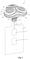
- the invention relates to a shaving unit 10 configured to be used in an electric shaver 1.
- the shaving unit 10 comprises a supporting member 20 and three hair-cutting units 30 supported by the supporting member 20.
- the number of hair-cutting units 30 can be chosen freely and does not necessarily need to be three, the number being at least two.
- Fig. 1 illustrates how the shaving unit 10 is combined with a main body 2 in an electric shaver 1, the supporting member 20 of the shaving unit 10 being coupled to the main body 2.
- the main body 2 can be of any suitable design and is only diagrammatically shown by means of dashed lines.
- the electric shaver 1 is a handheld device, and for the purpose of performing a shaving action on skin by means of the shaver 1, a user of the shaver 1 is supposed to take hold of the main body 2, to place the shaving unit 10 on the skin and to move the shaving unit 10 over the skin.
- the electric shaver 1 is shown in a normal orientation, which is an orientation in which the shaving unit 10 is positioned on top of the main body 2, and it is this orientation that is at the basis of terms as used in the present text for indicating positioning of components. Still, it is to be noted that the definitions of the shaving unit 10 and the electric shaver 1 in the attached claims are not restricted to this orientation, that is to say, the definitions are applicable to the shaving unit 10 and the shaver 1 in any possible orientation.
- the shaving unit 10 constitutes the part of the electric shaver 1 by means of which the action of cutting off hairs from the skin can actually be performed, while the main housing 2 may have a function in accommodating a motor 3 for driving the components of the shaving unit 10 involved in such action.
- the main housing 2 may further include means such as a rechargeable battery 4 for powering the motor 3.
- the shaving unit 10 and the main housing 2 are releasably connectable to each other, as known per se in the field of electric shavers, and if the supporting member 20 of the shaving unit 10 comprises a connecting member 21 accommodating a main drive shaft 22 which is coupled to the motor 3 in a connected condition of the shaving unit 10 to the main body 2.
- Fig. 1 This option is illustrated in Fig. 1 , wherein both the main drive shaft 22 and an output shaft 5 of the motor 3 are indicated through dashed lines.
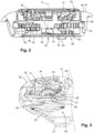
- the shaving unit 10 comprises an individual drive shaft 34 for each hair-cutting unit 30, and that in each of the hair-cutting units 30, the individual drive shaft 34 is releasably coupled to the internal cutting member 32 by means of a coupling member 35 of the internal cutting member 32.
- a notable aspect of the shaving unit 10 resides in the fact that the external cutting member 31 is rotatable about the central axis A c relative to the housing 40, and that the hair-cutting unit 30 comprises a transmission unit 60 by means of which this feature of the external cutting member 31 is actually realized.
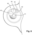
- the transmission unit 60 is accommodated in the housing 40 of the hair-cutting unit 30 and comprises:
- the number of intermediate transmission members 63, 64, 65 can be chosen freely and does not necessarily need to be three, the number being at least one.
- the intermediate transmission members 63, 64, 65 are positioned below the internal cutting member 32.
- the first transmission member 61 comprises a first gear wheel arranged on the coupling member 35 of the internal cutting member 32 co-axially relative to the central axis A c
- the second transmission member 62 comprises a second gear wheel arranged on an inner side of an annular flange portion 36 of the external cutting member 31 and co-axially relative to the central axis A c
- the intermediate transmission members 63, 64, 65 comprise intermediate gear wheels via which the first gear wheel is coupled to the second gear wheel.
- each intermediate transmission member 63, 64, 65 comprises a pair of gear wheels in stacked configuration.
- rotational bearings 42, 43, 44 of the respective intermediate transmission members 63, 64, 65 are included in an integral housing part 45, and the transmission members 63, 64, 65 are mounted to the housing part 45 by being rotatably arranged on the rotational bearings 42, 43, 44, while the position of the transmission members 63, 64, 65 in the direction of the central axis A c is fixed.
- a hair-cutting unit 30 of the shaving unit 10 comprises a housing 40 having a central axis A c , an external cutting member 31 supported by the housing 40, and an internal cutting member 32 covered by the external cutting member 31.
- the external cutting member 31 is rotatable about the central axis A c relative to the housing 40
- the internal cutting member 32 is rotatable about the central axis A c relative to the external cutting member 31.
- the hair-cutting unit 30 further comprises a transmission unit 60 which is accommodated in the housing 40 and which comprises a first transmission member 61 mounted to the internal cutting member 32, a second transmission member 62 mounted to the external cutting member 31, and at least one intermediate transmission member 63, 64, 65 via which the first transmission member 61 is coupled to the second transmission member 62 to convert a rotation of the internal cutting member 32 about the central axis A c into a rotation of the external cutting member 31 about the central axis A c .
- a transmission unit 60 which is accommodated in the housing 40 and which comprises a first transmission member 61 mounted to the internal cutting member 32, a second transmission member 62 mounted to the external cutting member 31, and at least one intermediate transmission member 63, 64, 65 via which the first transmission member 61 is coupled to the second transmission member 62 to convert a rotation of the internal cutting member 32 about the central axis A c into a rotation of the external cutting member 31 about the central axis A c .
Landscapes
- Life Sciences & Earth Sciences (AREA)
- Forests & Forestry (AREA)
- Engineering & Computer Science (AREA)
- Mechanical Engineering (AREA)
- Dry Shavers And Clippers (AREA)
Claims (12)
- Rasiereinheit (10) für einen Elektrorasierer (1), die ein Stützelement (20) und mindestens zwei Haarschneideeinheiten (30) umfasst, die von dem Stützelement (20) gestützt werden, wobei jede Haarschneideeinheit (30) umfasst:- ein Gehäuse (40), das eine Mittelachse (Ac) aufweist;- ein äußeres Schneidelement (31), das von dem Gehäuse (40) gestützt wird und einen ringförmigen Rasierbereich (33) umfasst, der eine Vielzahl von Haareintrittsöffnungen aufweist, wobei das äußere Schneidelement (31) in Bezug zum Gehäuse (40) um die Mittelachse (Ac) herum drehbar ist; und- ein inneres Schneidelement (32), das von dem äußeren Schneidelement (31) überdeckt wird und in Bezug zum äußeren Schneidelement (31) um die Mittelachse (Ac) herum drehbar ist und ein Kopplungselement (35) aufweist;wobei die Rasiereinheit (10) für jede Haarschneideeinheit (30) eine einzelne Antriebswelle (34) umfasst, die zum Drehen des inneren Schneidelements (32) in Bezug zum äußeren Schneidelement (31) um die Mittelachse (Ac) herum lösbar mit dem Kopplungselement des inneren Schneidelements (32) gekoppelt ist;wobei jede Haarschneideeinheit (30) eine Getriebeeinheit (60) umfasst, mit der das äußere Schneidelement (31) in Bezug zum Gehäuse (40) um die Mittelachse (Ac) drehbar ist, wobei die Getriebeeinheit (60) in dem Gehäuse (40) der Haarschneideeinheit (30) untergebracht ist und umfasst:- ein erstes Getriebeelement (61), das an dem inneren Schneidelement (32) montiert ist, um zusammen mit dem inneren Schneidelement (32) um die Mittelachse (Ac) herum drehbar zu sein;- ein zweites Getriebeelement (62), das an dem äußeren Schneidelement (31) montiert ist, um zusammen mit dem äußeren Schneidelement (31) um die Mittelachse (Ac) herum drehbar zu sein; und- mindestens ein Zwischengetriebeelement (63, 64, 65), über welches das erste Getriebeelement (61) mit dem zweiten Getriebeelement (62) gekoppelt ist, um eine Drehung des inneren Schneidelements (32) um die Mittelachse (Ac) herum in eine Drehung des äußeren Schneidelements (31) um die Mittelachse (Ac) herum umzuwandeln.
- Rasiereinheit (10) nach Anspruch 1, wobei:- jede Haarschneideeinheit (30) in Bezug zum Stützelement (20) um mindestens eine Schwenkachse herum schwenkbar ist; und- das Kopplungselement (35) des inneren Schneidelements (32) jeder Haarschneideeinheit (30) konfiguriert ist, um beim Schwenken der Haarschneideeinheit (30) um die mindestens eine Schwenkachse herum eine Drehkopplung mit der einzelnen Antriebswelle (34), die mit der Haarschneideeinheit (30) verknüpft ist, aufrechtzuerhalten.
- Rasiereinheit (10) nach Anspruch 2, wobei jede der einzelnen Antriebswellen (34) einen Kopplungskopf (38) umfasst, wobei das Kopplungselement (35) des inneren Schneidelements (32) jeder Haarschneideeinheit (30) einen Hohlraum (37) umfasst, der den Kopplungskopf (38) der einzelnen Antriebswelle (34), die mit der Haarschneideeinheit (30) verknüpft ist, aufnimmt, und wobei Oberflächen des Kopplungskopfes (38) und des Hohlraums (37) konfiguriert sind, um beim Schwenken der Haarschneideeinheit (30) um die mindestens eine Schwenkachse herum übereinander zu gleiten.
- Rasiereinheit (10) nach einem der Ansprüche 1-3, wobei die Getriebeeinheit (60) konfiguriert ist, um eine Drehung des inneren Schneidelements (32) um die Mittelachse (Ac) herum mit einer ersten Drehgeschwindigkeit in eine Drehung des äußeren Schneidelements (31) um die Mittelachse (Ac) herum mit einer zweiten Drehgeschwindigkeit umzuwandeln, wobei die zweite Drehgeschwindigkeit niedriger als die erste Drehgeschwindigkeit ist.
- Rasiereinheit (10) nach Anspruch 4, wobei die Getriebeeinheit (60) konfiguriert ist, um eine Geschwindigkeitsreduktionsrate in einem Bereich von etwa 20 bis 25 zu realisieren.
- Rasiereinheit (10) nach einem der Ansprüche 1-5, wobei die Getriebeeinheit (60) konfiguriert ist, um das externe Schneidelement (31) mit einer Drehgeschwindigkeit in einem Bereich von etwa 40 U/min bis 120 U/min laufen zu lassen.
- Rasiereinheit (10) nach einem der Ansprüche 1-6, wobei in der Getriebeeinheit (60):- das erste Getriebeelement (61) ein erstes Zahnrad umfasst, das koaxial in Bezug zur Mittelachse (Ac) auf dem Kopplungselement (35) des inneren Schneidelements (32) angeordnet ist;- das zweite Getriebeelement (62) ein zweites Zahnrad umfasst, das an einer Innenseite eines ringförmigen Flanschabschnitts (36) des äußeren Schneidelements (31) und koaxial in Bezug zur Mittelachse (Ac) angeordnet ist; und- das mindestens eine Zwischengetriebeelement (63, 64, 64) mindestens ein Zwischenzahnrad umfasst, über welches das erste Zahnrad mit dem zweiten Zahnrad gekoppelt ist, wobei jedes Zwischenzahnrad sein Drehlager (42, 43, 44) auf dem Gehäuse (40) angeordnet aufweist.
- Rasiereinheit (10) nach Anspruch 7, wobei die Getriebeeinheit (60) mindestens zwei Zwischenzahnräder (63, 64, 65) umfasst und wobei die Drehlager (42, 43, 44) der jeweiligen Zwischenzahnräder (63, 64, 65) in einem integralen Gehäuseteil (45) beinhaltet sind.
- Rasiereinheit (10) nach Anspruch 7 oder 8, wobei in der Getriebeeinheit (60) das mindestens eine Zwischengetriebeelement (63, 64, 65) ein Paar Zwischenzahnräder in gestapelter Konfiguration umfasst.
- Rasiereinheit (10) nach einem der Ansprüche 1-9, wobei das Gehäuse (40) jeder Haarschneideeinheit (30) eine Hautkontaktoberfläche (41) umfasst, die das äußere Schneidelement (31) der Haarschneideeinheit (30) umgibt.
- Elektrorasierer (1), umfassend:- einen Hauptkörper (2), der einen Motor (3) aufnimmt; und- eine Rasiereinheit (10) nach einem der Ansprüche 1-10, wobei das Stützelement (20) der Rasiereinheit (10) mit dem Hauptkörper (2) gekoppelt ist.
- Elektrorasierer (1) nach Anspruch 11, wobei:- das Stützelement (20) der Rasiereinheit (10) ein Verbindungselement (21) umfasst, mittels dessen die Rasiereinheit (10) lösbar mit dem Hauptkörper (2) verbunden ist;- das Verbindungselement (21) eine Hauptantriebswelle (22) aufnimmt, die in einem mit dem Hauptkörper (2) verbundenen Zustand der Rasiereinheit (10) mit dem Motor (3) gekoppelt ist; und- die Rasiereinheit (10) ein Getriebesystem (50) umfasst, um Drehung der Hauptantriebswelle (22) in Drehung der einzelnen Antriebswellen (34) jeder Haarschneideeinheit (30) der Rasiereinheit (10) umzuwandeln.
Applications Claiming Priority (2)
| Application Number | Priority Date | Filing Date | Title |
|---|---|---|---|
| EP21214282.2A EP4197721A1 (de) | 2021-12-14 | 2021-12-14 | Drehung eines externen schneidelements einer rasiereinheit |
| PCT/EP2022/084245 WO2023110461A1 (en) | 2021-12-14 | 2022-12-02 | Rotating an external cutting member of a shaving unit |
Publications (2)
| Publication Number | Publication Date |
|---|---|
| EP4448236A1 EP4448236A1 (de) | 2024-10-23 |
| EP4448236B1 true EP4448236B1 (de) | 2025-07-02 |
Family
ID=78851123
Family Applications (2)
| Application Number | Title | Priority Date | Filing Date |
|---|---|---|---|
| EP21214282.2A Withdrawn EP4197721A1 (de) | 2021-12-14 | 2021-12-14 | Drehung eines externen schneidelements einer rasiereinheit |
| EP22830175.0A Active EP4448236B1 (de) | 2021-12-14 | 2022-12-02 | Drehung eines externen schneidelements einer rasiereinheit |
Family Applications Before (1)
| Application Number | Title | Priority Date | Filing Date |
|---|---|---|---|
| EP21214282.2A Withdrawn EP4197721A1 (de) | 2021-12-14 | 2021-12-14 | Drehung eines externen schneidelements einer rasiereinheit |
Country Status (7)
| Country | Link |
|---|---|
| US (1) | US20250135667A1 (de) |
| EP (2) | EP4197721A1 (de) |
| JP (1) | JP7764959B2 (de) |
| KR (1) | KR20240119317A (de) |
| CN (1) | CN118382519A (de) |
| ES (1) | ES3041816T3 (de) |
| WO (1) | WO2023110461A1 (de) |
Families Citing this family (1)
| Publication number | Priority date | Publication date | Assignee | Title |
|---|---|---|---|---|
| USD884972S1 (en) * | 2018-04-12 | 2020-05-19 | Koninklijke Philips N.V. | Shaver |
Family Cites Families (7)
| Publication number | Priority date | Publication date | Assignee | Title |
|---|---|---|---|---|
| NL53921C (de) * | 1938-11-10 | |||
| CH376798A (de) * | 1960-04-28 | 1964-04-15 | Spengler Max | Trockenrasierapparat mit Schersieb |
| US6212776B1 (en) * | 1997-02-25 | 2001-04-10 | Izuma Products Company | Electric shaver |
| US5983501A (en) * | 1997-04-02 | 1999-11-16 | Izumi Products Company | Electric shaver |
| JP4076266B2 (ja) * | 1997-04-02 | 2008-04-16 | 株式会社泉精器製作所 | 電気かみそり |
| US8397388B1 (en) * | 2011-11-03 | 2013-03-19 | Hy Steinberg | Rotary shaver platform rotation system |
| JP6200918B2 (ja) * | 2015-07-09 | 2017-09-20 | 株式会社泉精器製作所 | ロータリー式電気かみそり |
-
2021
- 2021-12-14 EP EP21214282.2A patent/EP4197721A1/de not_active Withdrawn
-
2022
- 2022-12-02 US US18/715,186 patent/US20250135667A1/en active Pending
- 2022-12-02 ES ES22830175T patent/ES3041816T3/es active Active
- 2022-12-02 JP JP2024527491A patent/JP7764959B2/ja active Active
- 2022-12-02 KR KR1020247023407A patent/KR20240119317A/ko active Pending
- 2022-12-02 WO PCT/EP2022/084245 patent/WO2023110461A1/en not_active Ceased
- 2022-12-02 CN CN202280082237.1A patent/CN118382519A/zh active Pending
- 2022-12-02 EP EP22830175.0A patent/EP4448236B1/de active Active
Also Published As
| Publication number | Publication date |
|---|---|
| EP4197721A1 (de) | 2023-06-21 |
| JP2024541332A (ja) | 2024-11-08 |
| EP4448236A1 (de) | 2024-10-23 |
| CN118382519A (zh) | 2024-07-23 |
| US20250135667A1 (en) | 2025-05-01 |
| JP7764959B2 (ja) | 2025-11-06 |
| WO2023110461A1 (en) | 2023-06-22 |
| KR20240119317A (ko) | 2024-08-06 |
| ES3041816T3 (en) | 2025-11-14 |
Similar Documents
| Publication | Publication Date | Title |
|---|---|---|
| EP2180983B1 (de) | Körperpflegevorrichtung | |
| EP2281670B1 (de) | Elektrischer Rotationsrasierapparat | |
| US7426785B2 (en) | Multi type head moving shaver | |
| JP7457482B2 (ja) | ロータリー式電気かみそり | |
| US20100064520A1 (en) | Modular grooming tool with dual motors | |
| CA2227054C (en) | Electric shaver | |
| EP3115160B1 (de) | Elektrischer rotationsrasierapparat | |
| US20080086887A1 (en) | Modular grooming tool | |
| WO1992006825A1 (en) | Oscillating shaver | |
| EP3069832B1 (de) | Elektrischer rasierapparat und dessen kopf | |
| JP2007506473A (ja) | 電気毛切断装置 | |
| US7020965B2 (en) | Shaving device | |
| US20250135667A1 (en) | Rotating an external cutting member of a shaving unit | |
| JPS60212188A (ja) | ひげ剃りユニツト | |
| WO2005107373A2 (en) | Shaving apparatus | |
| JP6424278B2 (ja) | マルチグルーマー | |
| JPH0857169A (ja) | 電気かみそり | |
| EP4363178B1 (de) | Übertragungssystem zur verwendung in einem rasierkopf eines elektrischen rasierers | |
| US20250381688A1 (en) | Electric shaver | |
| US11351685B2 (en) | Hair grooming appliance | |
| KR200333827Y1 (ko) | 수동식 동력전달구조 | |
| JP2731199B2 (ja) | 振動式電気かみそり | |
| JPH10165666A (ja) | 電気剃毛器 | |
| HK1151001A (en) | Rotary electric shaver | |
| JPS6058676B2 (ja) | 往復式電気かみそり |
Legal Events
| Date | Code | Title | Description |
|---|---|---|---|
| STAA | Information on the status of an ep patent application or granted ep patent |
Free format text: STATUS: UNKNOWN |
|
| STAA | Information on the status of an ep patent application or granted ep patent |
Free format text: STATUS: THE INTERNATIONAL PUBLICATION HAS BEEN MADE |
|
| PUAI | Public reference made under article 153(3) epc to a published international application that has entered the european phase |
Free format text: ORIGINAL CODE: 0009012 |
|
| STAA | Information on the status of an ep patent application or granted ep patent |
Free format text: STATUS: REQUEST FOR EXAMINATION WAS MADE |
|
| 17P | Request for examination filed |
Effective date: 20240715 |
|
| AK | Designated contracting states |
Kind code of ref document: A1 Designated state(s): AL AT BE BG CH CY CZ DE DK EE ES FI FR GB GR HR HU IE IS IT LI LT LU LV MC ME MK MT NL NO PL PT RO RS SE SI SK SM TR |
|
| GRAP | Despatch of communication of intention to grant a patent |
Free format text: ORIGINAL CODE: EPIDOSNIGR1 |
|
| STAA | Information on the status of an ep patent application or granted ep patent |
Free format text: STATUS: GRANT OF PATENT IS INTENDED |
|
| INTG | Intention to grant announced |
Effective date: 20250131 |
|
| DAV | Request for validation of the european patent (deleted) | ||
| DAX | Request for extension of the european patent (deleted) | ||
| GRAS | Grant fee paid |
Free format text: ORIGINAL CODE: EPIDOSNIGR3 |
|
| GRAA | (expected) grant |
Free format text: ORIGINAL CODE: 0009210 |
|
| STAA | Information on the status of an ep patent application or granted ep patent |
Free format text: STATUS: THE PATENT HAS BEEN GRANTED |
|
| AK | Designated contracting states |
Kind code of ref document: B1 Designated state(s): AL AT BE BG CH CY CZ DE DK EE ES FI FR GB GR HR HU IE IS IT LI LT LU LV MC ME MK MT NL NO PL PT RO RS SE SI SK SM TR |
|
| REG | Reference to a national code |
Ref country code: GB Ref legal event code: FG4D |
|
| REG | Reference to a national code |
Ref country code: CH Ref legal event code: EP |
|
| REG | Reference to a national code |
Ref country code: DE Ref legal event code: R096 Ref document number: 602022017082 Country of ref document: DE |
|
| REG | Reference to a national code |
Ref country code: IE Ref legal event code: FG4D |
|
| REG | Reference to a national code |
Ref country code: NL Ref legal event code: MP Effective date: 20250702 |
|
| REG | Reference to a national code |
Ref country code: ES Ref legal event code: FG2A Ref document number: 3041816 Country of ref document: ES Kind code of ref document: T3 Effective date: 20251114 |
|
| PG25 | Lapsed in a contracting state [announced via postgrant information from national office to epo] |
Ref country code: PT Free format text: LAPSE BECAUSE OF FAILURE TO SUBMIT A TRANSLATION OF THE DESCRIPTION OR TO PAY THE FEE WITHIN THE PRESCRIBED TIME-LIMIT Effective date: 20251103 |
|
| PG25 | Lapsed in a contracting state [announced via postgrant information from national office to epo] |
Ref country code: NL Free format text: LAPSE BECAUSE OF FAILURE TO SUBMIT A TRANSLATION OF THE DESCRIPTION OR TO PAY THE FEE WITHIN THE PRESCRIBED TIME-LIMIT Effective date: 20250702 |
|
| REG | Reference to a national code |
Ref country code: AT Ref legal event code: MK05 Ref document number: 1808743 Country of ref document: AT Kind code of ref document: T Effective date: 20250702 |
|
| PG25 | Lapsed in a contracting state [announced via postgrant information from national office to epo] |
Ref country code: IS Free format text: LAPSE BECAUSE OF FAILURE TO SUBMIT A TRANSLATION OF THE DESCRIPTION OR TO PAY THE FEE WITHIN THE PRESCRIBED TIME-LIMIT Effective date: 20251102 |
|
| PG25 | Lapsed in a contracting state [announced via postgrant information from national office to epo] |
Ref country code: NO Free format text: LAPSE BECAUSE OF FAILURE TO SUBMIT A TRANSLATION OF THE DESCRIPTION OR TO PAY THE FEE WITHIN THE PRESCRIBED TIME-LIMIT Effective date: 20251002 |
|
| REG | Reference to a national code |
Ref country code: LT Ref legal event code: MG9D |
|
| PG25 | Lapsed in a contracting state [announced via postgrant information from national office to epo] |
Ref country code: AT Free format text: LAPSE BECAUSE OF FAILURE TO SUBMIT A TRANSLATION OF THE DESCRIPTION OR TO PAY THE FEE WITHIN THE PRESCRIBED TIME-LIMIT Effective date: 20250702 |
|
| PG25 | Lapsed in a contracting state [announced via postgrant information from national office to epo] |
Ref country code: FI Free format text: LAPSE BECAUSE OF FAILURE TO SUBMIT A TRANSLATION OF THE DESCRIPTION OR TO PAY THE FEE WITHIN THE PRESCRIBED TIME-LIMIT Effective date: 20250702 |
|
| PG25 | Lapsed in a contracting state [announced via postgrant information from national office to epo] |
Ref country code: HR Free format text: LAPSE BECAUSE OF FAILURE TO SUBMIT A TRANSLATION OF THE DESCRIPTION OR TO PAY THE FEE WITHIN THE PRESCRIBED TIME-LIMIT Effective date: 20250702 |
|
| PGFP | Annual fee paid to national office [announced via postgrant information from national office to epo] |
Ref country code: FR Payment date: 20251222 Year of fee payment: 4 |
|
| PG25 | Lapsed in a contracting state [announced via postgrant information from national office to epo] |
Ref country code: GR Free format text: LAPSE BECAUSE OF FAILURE TO SUBMIT A TRANSLATION OF THE DESCRIPTION OR TO PAY THE FEE WITHIN THE PRESCRIBED TIME-LIMIT Effective date: 20251003 |
|
| PG25 | Lapsed in a contracting state [announced via postgrant information from national office to epo] |
Ref country code: CZ Free format text: LAPSE BECAUSE OF FAILURE TO SUBMIT A TRANSLATION OF THE DESCRIPTION OR TO PAY THE FEE WITHIN THE PRESCRIBED TIME-LIMIT Effective date: 20250702 Ref country code: SE Free format text: LAPSE BECAUSE OF FAILURE TO SUBMIT A TRANSLATION OF THE DESCRIPTION OR TO PAY THE FEE WITHIN THE PRESCRIBED TIME-LIMIT Effective date: 20250702 |
|
| PG25 | Lapsed in a contracting state [announced via postgrant information from national office to epo] |
Ref country code: LV Free format text: LAPSE BECAUSE OF FAILURE TO SUBMIT A TRANSLATION OF THE DESCRIPTION OR TO PAY THE FEE WITHIN THE PRESCRIBED TIME-LIMIT Effective date: 20250702 |
|
| PG25 | Lapsed in a contracting state [announced via postgrant information from national office to epo] |
Ref country code: BG Free format text: LAPSE BECAUSE OF FAILURE TO SUBMIT A TRANSLATION OF THE DESCRIPTION OR TO PAY THE FEE WITHIN THE PRESCRIBED TIME-LIMIT Effective date: 20250702 Ref country code: PL Free format text: LAPSE BECAUSE OF FAILURE TO SUBMIT A TRANSLATION OF THE DESCRIPTION OR TO PAY THE FEE WITHIN THE PRESCRIBED TIME-LIMIT Effective date: 20250702 |
|
| PG25 | Lapsed in a contracting state [announced via postgrant information from national office to epo] |
Ref country code: RS Free format text: LAPSE BECAUSE OF FAILURE TO SUBMIT A TRANSLATION OF THE DESCRIPTION OR TO PAY THE FEE WITHIN THE PRESCRIBED TIME-LIMIT Effective date: 20251002 |
|
| PG25 | Lapsed in a contracting state [announced via postgrant information from national office to epo] |
Ref country code: RO Free format text: LAPSE BECAUSE OF FAILURE TO SUBMIT A TRANSLATION OF THE DESCRIPTION OR TO PAY THE FEE WITHIN THE PRESCRIBED TIME-LIMIT Effective date: 20250702 |
|
| PG25 | Lapsed in a contracting state [announced via postgrant information from national office to epo] |
Ref country code: SM Free format text: LAPSE BECAUSE OF FAILURE TO SUBMIT A TRANSLATION OF THE DESCRIPTION OR TO PAY THE FEE WITHIN THE PRESCRIBED TIME-LIMIT Effective date: 20250702 |
|
| PGFP | Annual fee paid to national office [announced via postgrant information from national office to epo] |
Ref country code: ES Payment date: 20260122 Year of fee payment: 4 |
|
| PG25 | Lapsed in a contracting state [announced via postgrant information from national office to epo] |
Ref country code: DK Free format text: LAPSE BECAUSE OF FAILURE TO SUBMIT A TRANSLATION OF THE DESCRIPTION OR TO PAY THE FEE WITHIN THE PRESCRIBED TIME-LIMIT Effective date: 20250702 |
|
| PGFP | Annual fee paid to national office [announced via postgrant information from national office to epo] |
Ref country code: DE Payment date: 20251229 Year of fee payment: 4 |
|
| PG25 | Lapsed in a contracting state [announced via postgrant information from national office to epo] |
Ref country code: IT Free format text: LAPSE BECAUSE OF FAILURE TO SUBMIT A TRANSLATION OF THE DESCRIPTION OR TO PAY THE FEE WITHIN THE PRESCRIBED TIME-LIMIT Effective date: 20250702 |
|
| REG | Reference to a national code |
Ref country code: CH Ref legal event code: W10 Free format text: ST27 STATUS EVENT CODE: U-0-0-W10-W00 (AS PROVIDED BY THE NATIONAL OFFICE) Effective date: 20260423 |
|
| PG25 | Lapsed in a contracting state [announced via postgrant information from national office to epo] |
Ref country code: SK Free format text: LAPSE BECAUSE OF FAILURE TO SUBMIT A TRANSLATION OF THE DESCRIPTION OR TO PAY THE FEE WITHIN THE PRESCRIBED TIME-LIMIT Effective date: 20250702 Ref country code: EE Free format text: LAPSE BECAUSE OF FAILURE TO SUBMIT A TRANSLATION OF THE DESCRIPTION OR TO PAY THE FEE WITHIN THE PRESCRIBED TIME-LIMIT Effective date: 20250702 |
|
| PLBE | No opposition filed within time limit |
Free format text: ORIGINAL CODE: 0009261 |
|
| STAA | Information on the status of an ep patent application or granted ep patent |
Free format text: STATUS: NO OPPOSITION FILED WITHIN TIME LIMIT |