EP4450177A1 - Verbesserte leistung eines getränkespenders - Google Patents
Verbesserte leistung eines getränkespenders Download PDFInfo
- Publication number
- EP4450177A1 EP4450177A1 EP23168779.9A EP23168779A EP4450177A1 EP 4450177 A1 EP4450177 A1 EP 4450177A1 EP 23168779 A EP23168779 A EP 23168779A EP 4450177 A1 EP4450177 A1 EP 4450177A1
- Authority
- EP
- European Patent Office
- Prior art keywords
- vessel
- swivel element
- cleaning
- cleaned
- swivel
- Prior art date
- Legal status (The legal status is an assumption and is not a legal conclusion. Google has not performed a legal analysis and makes no representation as to the accuracy of the status listed.)
- Withdrawn
Links
Images




Classifications
-
- B—PERFORMING OPERATIONS; TRANSPORTING
- B08—CLEANING
- B08B—CLEANING IN GENERAL; PREVENTION OF FOULING IN GENERAL
- B08B9/00—Cleaning hollow articles by methods or apparatus specially adapted thereto
- B08B9/08—Cleaning containers, e.g. tanks
- B08B9/20—Cleaning containers, e.g. tanks by using apparatus into or on to which containers, e.g. bottles, jars, cans are brought
- B08B9/28—Cleaning containers, e.g. tanks by using apparatus into or on to which containers, e.g. bottles, jars, cans are brought the apparatus cleaning by splash, spray, or jet application, with or without soaking
- B08B9/34—Arrangements of conduits or nozzles
-
- B—PERFORMING OPERATIONS; TRANSPORTING
- B08—CLEANING
- B08B—CLEANING IN GENERAL; PREVENTION OF FOULING IN GENERAL
- B08B9/00—Cleaning hollow articles by methods or apparatus specially adapted thereto
- B08B9/08—Cleaning containers, e.g. tanks
- B08B9/0804—Cleaning containers having tubular shape, e.g. casks, barrels, drums
- B08B9/0813—Cleaning containers having tubular shape, e.g. casks, barrels, drums by the force of jets or sprays
-
- B—PERFORMING OPERATIONS; TRANSPORTING
- B08—CLEANING
- B08B—CLEANING IN GENERAL; PREVENTION OF FOULING IN GENERAL
- B08B9/00—Cleaning hollow articles by methods or apparatus specially adapted thereto
- B08B9/08—Cleaning containers, e.g. tanks
- B08B9/083—Removing scrap from containers, e.g. removing labels
- B08B9/0835—Removing remnants of closures from bottle necks
-
- B—PERFORMING OPERATIONS; TRANSPORTING
- B08—CLEANING
- B08B—CLEANING IN GENERAL; PREVENTION OF FOULING IN GENERAL
- B08B9/00—Cleaning hollow articles by methods or apparatus specially adapted thereto
- B08B9/08—Cleaning containers, e.g. tanks
- B08B9/093—Cleaning containers, e.g. tanks by the force of jets or sprays
- B08B9/0936—Cleaning containers, e.g. tanks by the force of jets or sprays using rotating jets
-
- B—PERFORMING OPERATIONS; TRANSPORTING
- B08—CLEANING
- B08B—CLEANING IN GENERAL; PREVENTION OF FOULING IN GENERAL
- B08B9/00—Cleaning hollow articles by methods or apparatus specially adapted thereto
- B08B9/08—Cleaning containers, e.g. tanks
- B08B9/20—Cleaning containers, e.g. tanks by using apparatus into or on to which containers, e.g. bottles, jars, cans are brought
-
- B—PERFORMING OPERATIONS; TRANSPORTING
- B08—CLEANING
- B08B—CLEANING IN GENERAL; PREVENTION OF FOULING IN GENERAL
- B08B9/00—Cleaning hollow articles by methods or apparatus specially adapted thereto
- B08B9/08—Cleaning containers, e.g. tanks
- B08B9/20—Cleaning containers, e.g. tanks by using apparatus into or on to which containers, e.g. bottles, jars, cans are brought
- B08B9/28—Cleaning containers, e.g. tanks by using apparatus into or on to which containers, e.g. bottles, jars, cans are brought the apparatus cleaning by splash, spray, or jet application, with or without soaking
-
- B—PERFORMING OPERATIONS; TRANSPORTING
- B08—CLEANING
- B08B—CLEANING IN GENERAL; PREVENTION OF FOULING IN GENERAL
- B08B9/00—Cleaning hollow articles by methods or apparatus specially adapted thereto
- B08B9/08—Cleaning containers, e.g. tanks
- B08B9/0821—Handling or manipulating containers, e.g. moving or rotating containers in cleaning devices, conveying to or from cleaning devices
- B08B9/0826—Handling or manipulating containers, e.g. moving or rotating containers in cleaning devices, conveying to or from cleaning devices the containers being brought to the cleaning device
-
- B—PERFORMING OPERATIONS; TRANSPORTING
- B08—CLEANING
- B08B—CLEANING IN GENERAL; PREVENTION OF FOULING IN GENERAL
- B08B9/00—Cleaning hollow articles by methods or apparatus specially adapted thereto
- B08B9/08—Cleaning containers, e.g. tanks
- B08B9/20—Cleaning containers, e.g. tanks by using apparatus into or on to which containers, e.g. bottles, jars, cans are brought
- B08B9/28—Cleaning containers, e.g. tanks by using apparatus into or on to which containers, e.g. bottles, jars, cans are brought the apparatus cleaning by splash, spray, or jet application, with or without soaking
- B08B9/283—Cleaning containers, e.g. tanks by using apparatus into or on to which containers, e.g. bottles, jars, cans are brought the apparatus cleaning by splash, spray, or jet application, with or without soaking by gas jets
-
- B—PERFORMING OPERATIONS; TRANSPORTING
- B08—CLEANING
- B08B—CLEANING IN GENERAL; PREVENTION OF FOULING IN GENERAL
- B08B9/00—Cleaning hollow articles by methods or apparatus specially adapted thereto
- B08B9/08—Cleaning containers, e.g. tanks
- B08B9/20—Cleaning containers, e.g. tanks by using apparatus into or on to which containers, e.g. bottles, jars, cans are brought
- B08B9/42—Cleaning containers, e.g. tanks by using apparatus into or on to which containers, e.g. bottles, jars, cans are brought the apparatus being characterised by means for conveying or carrying containers therethrough
- B08B9/426—Grippers for bottles
-
- B—PERFORMING OPERATIONS; TRANSPORTING
- B67—OPENING, CLOSING OR CLEANING BOTTLES, JARS OR SIMILAR CONTAINERS; LIQUID HANDLING
- B67D—DISPENSING, DELIVERING OR TRANSFERRING LIQUIDS, NOT OTHERWISE PROVIDED FOR
- B67D1/00—Apparatus or devices for dispensing beverages on draught
- B67D1/07—Cleaning beverage-dispensing apparatus
Definitions
- the present invention relates to vessel washer, particularly a washer for a bottle, a carafe, a coffee cup, a tea cup or the like.
- the present invention intends to avoid use of plastic bottles for beverage.
- the present invention also intends to avoid transport of beverage bottles.
- the present invention relates to a vessel cleaning apparatus that is used in combination with a beverage dispenser.
- a user first washes his bottle at the vessel cleaning apparatus before he refills his bottle with the desired beverage.
- the bottles of the users must be cleaned fast and reliably without relying on time-consuming washing of a bottle in a dishwasher.
- the fast washing of the beverage vessel is part of a refill concept.
- DE 42 29 580 A1 discloses that a bottle is rinsed by a nozzle tube introduced into the interior of the bottle.
- EP 0 894 543 A1 discloses a method and machine for rinsing or sterilizing a bottle with a movable nozzle penetrating into the bottle.
- the rinsing machines of the prior art are too bulky to be installed in the next to a beverage dispenser, such as in an office environment, a hotel, a public transport facility, a hospital, a nursing home or the like. Further, the bottle washing apparatus of the prior art are too slow to be accepted by users of a beverage dispenser. A further drawback of prior art washing machines is that the can not reproducibly clean odd shaped beverage vessels.
- the object of the present invention is a chief by a vessel cleaning apparatus according to claim 1, a method of cleaning a vessel according to claim 15 and a method of providing operation instructions for a controller of a vessel cleaning apparatus according to claim 16.
- the vessel cleaning apparatus comprises a first swivel element having a vessel cleaning nozzle and a second swivel element connected to the first swivel element by a first hinge element.
- a first end of a vessel cleaning conduit is connected to the vessel cleaning nozzle.
- An actuation means is configured for pivoting the first swivel element with respect to the second swivel element.
- the second end of the vessel cleaning conduit is in fluid communication with the source of pressurized cleaning liquid in a cleaning status of the vessel cleaning apparatus.
- a first drive may be coupled to the second swivel element and configured to rotate the first swivel element around a longitudinal axis of the vessel to be cleaned.
- a second drive may be coupled to the second swivel element and configured to move the second swivel element along the longitudinal axis of the vessel to be cleaned.
- the vessel cleaning nozzle can be positioned close to the interior walls of a vessel, such as the interior of the side wall, the interior of the bottom wall and the interior of the shoulder wall. Since the vessel cleaning nozzle is positioned close to the interior wall of the vessel, the pressurized cleaning liquid impinges under a higher pressure on the interior wall of the beverage vessel.
- the vessel cleaning apparatus has the advantage that the pressurized cleaning liquid can be ejected on any predetermined position in the interior of the vessel under different angles. This is particularly advantage for cleaning the edge between the interior bottom wall and the interior side wall.
- the vessel cleaning conduit may pass through the first swivel element and the second swivel element to the vessel cleaning nozzle in the first swivel element.
- the second swivel element may be positioned at the end of a rod or be part of the rod that is moved into the interior of the vessel.
- the pressurized cleaning liquid may have a temperature of 75 °C to 95 °C, preferably between 80 °C to 90 °C.
- the pressurized cleaning liquid is demineralized water, such as a reverse osmosis water.
- the reverse osmosis water may be supplied from a reverse osmosis filter of a beverage dispenser positioned in the vicinity of the vessel cleaning apparatus. Unlike cleaning agent demineralized water does not cause formation of foam.
- the first surface of the first swivel element may be convexly rounded or inwardly tapered towards the second swivel element, wherein the first surface of the first swivel element faces the second swivel element.
- the first surface of the second swivel element may be convexly rounded or inwardly tapered towards the first swivel element, wherein the first surface of the second swivel element faces the first swivel element.
- the first swivel element may be extended in its longitudinal direction by an actor. Thereby, a greater degree of freedom and flexibility for cleaning the interior of the vessel is achieved, since the vessel cleaning nozzle can be positioned closer to the interior walls of the vessel.
- the vessel cleaning apparatus may comprise a third swivel element that is connected at its first side pivotably by a second hinge element to the second swivel element, wherein the second side of the third swivel element is coupled with the first drive and the second drive.
- the third swivel element may be positioned at the end of the rod that is moved into the interior of the vessel or the third swivel element may be the end of a rod that is moved into the interior of the vessel.
- This embodiment has the advantage that the vessel cleaning nozzle can be positioned very close to any position in the interior of a vessel to improve cleaning of the interior of the vessel.
- the first surface of the second swivel element may be convexly rounded or inwardly tapered towards the third swivel element, wherein the first surface of the second swivel element faces the third swivel element.
- the first surface of the third swivel element may be convexly rounded or inwardly tapered towards the second swivel element, wherein the first surface of the third swivel element faces the second swivel element.
- a first end of a vessel drying conduit may be in fluid communication with the vessel cleaning nozzle.
- the second and of the vessel drying conduit may be in fluid communication with a source of a pressurized gas in a drying status of the vessel cleaning apparatus.
- the vessel cleaning apparatus performs a washing operation in its cleaning status, and the vessel cleaning apparatus performs a drying operation in its drying status.
- pressurized gas is ejected out of a vessel drying nozzle and presses residual cleaning fluid out of the vessel to try the vessel.
- the pressurized gas may be carbon dioxide.
- Carbon dioxide is available in pressurized bottles and fulfills the legal requirements for food and a beverage.
- the pressurized carbon dioxide is provided by the carbon dioxide bottle of the carbonization device of the beverage dispenser.
- the vessel cleaning apparatus comprises at least one valve that is configured to couple the second end of the vessel cleaning conduit with the source of pressurized cleaning liquid or with the source of the pressurized gas.
- the vessel cleaning conduit and seconds conduit are formed integral and there is only one conduit passing to the vessel drying nozzle.
- the actuation means may be a string passing the first swivel element and second swivel element.
- the string may pass through the first swivel element and the second swivel element, or the string may pass along the first swivel element and second swivel element and pass through a guide positioned at the outer surface of the first swivel element and the second swivel element.
- the string element is adapted to pivot the first swivel element in a first pivoting direction.
- the string may be fixed at the first swivel element.
- a first elastic element is formed between the first swivel element and the second swivel element. The first elastic element biases the first swivel element in a second pivoting direction opposite to the first pivoting direction.
- the advantage of this embodiment is that the actor may be positioned remote from the vessel cleaning nozzle and vessel drying nozzle.
- the first swivel element may be pivoted in a range of +/- 120°, preferably in a range of +/- 150° relative the second swivel element.
- the string may pass the third swivel element, wherein the string is configured to pivot the second swivel element in a first pivoting direction.
- a second elastic element is formed between the second swivel element and the third swivel element. The second elastic element biases the second swivel element in a second pivoting direction opposite to the first pivoting direction relative to the third swivel element.
- the string may pass through the third swivel element, or the string may pass along the third swivel and pass through a guide positioned at the outer surface of the first swivel element and the second swivel element
- the first swivel element may be prevented in a range of +/- 120°, preferably in a range of +/- 150° relative the third swivel element.
- the source of the pressurized cleaning liquid may be a receptacle comprising a first inlet, a second inlet and a first outlet.
- the first inlet is connected to a cleaning liquid supply by a first inlet valve.
- the second inlet is connected to the pressurized gas source by a second inlet valve.
- the first outlet is connected to the second end of the vessel cleaning conduit by a first inlet valve.
- the vessel cleaning apparatus may comprise a controller connected to the first inlet valve, the second inlet valve and the first outlet valve. The controller is configured to open the first outlet valve and the second inlet valve and to close the first inlet valve in a cleaning status of the cleaning apparatus such that the pressurized gas presses the cleaning liquid in the receptacle into the first conduit. Thereby, the cleaning liquid is ejected by the vessel cleaning nozzle.
- This embodiment has the advantage that no pump is required to eject the cleaning liquid through the vessel cleaning nozzle.
- the controller is also configured to open the first inlet valve and to close the second inlet valve and the first outlet valve in a third status of the vessel cleaning apparatus such that cleaning liquid flows from a cleaning liquid supply into the receptacle.
- the cleaning liquid supply may be a reverse osmosis filter, such as the reverse osmosis filter of the beverage dispenser in the vicinity of the vessel cleaning apparatus.
- the reverse osmosis filter may be provided independently of the beverage dispenser. In one embodiment, the reverse osmosis filter may be part of the vessel cleaning apparatus.
- the clamping device comprises an iris diaphragm configured to clamp the vessel in its closed state and to release the vessel in its opened state.
- the vessel In the opened state of the iris diaphragm the vessel can be removed from the clamping device and inserted into the clamping device.
- the iris diaphragm clamps the bottle at its neck or at its side walls.
- the invention also discloses a vessel mouth cleaning device having an opening, wherein at least one mouth cleaning nozzle is arranged in the opening and mouth cleaning conduit having a first end is coupled to the at least one mouth cleaning nozzle. A second end of the mouth cleaning conduit is in fluid communication with a source of the pressurized cleaning liquid in the cleaning status of the vessel cleaning apparatus.
- the mouth of the vessel is positioned in the mouth cleaning device, when clamped by the clamping device.
- At least one mouth cleaningnozzle is directed to the vessel mouth and emits cleaning liquid and/or pressurized gas. It is possible to arrange a plurality of mouth cleaningnozzles in an opening of the vessel cleaning apparatus to clean the vessel mouth from all sides.
- the opening may be an annular opening. In an alternative embodiment it is conceivable to rotate at least one mouth cleaningnozzle around the bottle neck device to clean the vessel mouth from all sides.
- the at least one mouth dryingnozzle may be connected by a mouth drying conduit and a valve to the source of pressurized gas to dry the mouth of the bottle.
- the second end of the mouth cleaning conduit may be in fluid communication with the source of pressurized gas in the drying status of the vessel cleaning apparatus. Thereby, the vessel mouth is dried.
- the mouth cleaning conduit and mouth cleaning conduit are formed integrally and there is only one conduit passing to at least one cleaning and drying nozzle.
- the second swivel element is positioned at a first end of a rod.
- the rod is driven by the first drive and the second drive.
- the first drive, the second drive and the actuation means are coupled to the controller.
- the controller is configured to receive the type of vessel to be cleaned.
- the controller may receive the type of vessel by a user input on a user interface, by a sensor, by an RFID element coupled to the vessel or by a mobile communication device.
- the controller is configured to load data about a path the first swivel element shall pass from a database based on the receive the type of vessel.
- the controller is configured to instruct the first drive, the second drive and the actuation means depending on the data about the shape of the vessel to be cleaned. It is an advantage of the present invention that the vessel cleaning nozzle and/or the vessel drying nozzle can be positioned at any angel and position to reproducible clean a beverage vessel having an arbitrary shape.
- the third swivel element is positioned at the end of the rod.
- the rod may be driven by the first drive and the second drive.
- the first drive, the second drive and the actuation means are coupled to the controller.
- the controller is configured to receive the type of vessel to be cleaned.
- the controller may receive the type of vessel by a user input on a user interface, by a sensor, by an RFID element coupled to the vessel or by a mobile communication device.
- the controller is configured to load data a path the first swivel element shall pass to be cleaned from a database based on the receive the type of vessel.
- the controller is configured to instruct the first drive, the second drive and the actuation means depending on the data about the shape of the vessel to be cleaned.
- the controller instructs the first drive, the second drive and the actuation means, how to move the first swivel element in the interior of the beverage vessel such that the vessel is cleaned in the most efficient way depending on the shape of the vessel.
- the vessel is clamped by the clamping device upside down.
- the controller instructs the second drive to move the first swivel element upwards towards the interior bottom wall of the vessel.
- the controller instructs the source of the pressurized cleaning liquid to output the pressurized cleaning liquid.
- the controller instructs the first drive to rotate the rod and the first swivel element, and the actuation means to increasingly pivot the first swivel element.
- the pressurized cleaning fluid impinges on the bottom wall of the vessel in a generally helically shaped pattern. Thereafter, the edge between the interior bottom wall and the interior side wall is cleaned by ejecting pressurized cleaning fluid from the vessel cleaning nozzle to the edge.
- the controller instructs the actuation means to keep the first swivel element in a pivoted state, the first drive to rotate the rod and the second drive to move the first swivel element away from the bottom wall. Thereby, the interior side walls of the vessel are cleaned.
- the controller may instruct the actuation means to pivot the first swivel element to an angle of more than 80°, preferably more than 90°, most preferred more than 100° with respect to the rod. Thereby, the shoulder of the bottle can be cleaned.
- the angle of the first swivel element with respect to the rod is reduced to a lower value, such that the first swivel element can pass through the bottle neck.
- the controller instructs the source of the pressurized cleaning fluid to stop supplying pressurized cleaning fluid and instructs the source of pressurized gas to supply pressurized gas. Thereafter, the above described instructions are passed to the first drive, second drive and actuation means to dry the vessel.
- the invention also discloses a method of cleaning a vessel comprising the step of receiving a type of vessel to be cleaned by a controller.
- the method loads data about a path the first swivel element shall pass from a database based on the received type of vessel.
- the method clamps the vessel to be cleaned by a clamping device.
- the method instructs an actuation means to pivot a first swivel element with respect to a second swivel element by the controller depending on the data about the shape of vessel to be cleaned.
- the method instructs a first drive coupled to the second swivel element to rotate the first swivel element around a longitudinal axis of the vessel to be cleaned by the controller depending on the data about the shape of vessel to be cleaned.
- the method also instructs a second drive coupled with the second swivel element to move the second swivel element along the longitudinal axis of the vessel to be cleaned by the controller depending on the data about the shape of vessel to be cleaned. Further, the method instructs a source of pressurized cleaning liquid to eject the cleaning liquid through a vessel cleaning nozzle formed in the first swivel element by the controller.
- the database may be any memory in a computer.
- the term "path the first swivel element shall pass” includes position and orientation of the first swivel element during cleaning the vessel.
- the invention also discloses a lid cleaning apparatus, comprising a first swivel element having a vessel cleaning nozzle and a second swivel element connected to the first swivel element by a first hinge element.
- a first end of a vessel cleaning conduit is connected to the vessel cleaning nozzle.
- An actuation means is configured for pivoting the first swivel element with respect to the second swivel element.
- An optional first drive is coupled to the second swivel element and configured to rotate the first swivel element around a longitudinal axis of the lid to be cleaned.
- An optional second drive is coupled to the second swivel element and configured to move the second swivel element along the longitudinal axis of the lid to be cleaned.
- the second end of the vessel cleaning conduit is in fluid communication with the source of pressurized cleaning liquid in a cleaning status of the lid cleaning apparatus.
- the lid cleaning apparatus may be embodied as described above with respect to the vessel cleaning apparatus.
- the invention discloses a vessel drying apparatus, comprising a first swivel element having a drying nozzle and a second swivel element connected to the first swivel element by a first hinge element.
- the vessel drying apparatus comprises a first swivel element having a nozzle and a second swivel element connected to the first swivel element by a first hinge element.
- a first end of a vessel drying conduit is connected to the vessel drying nozzle.
- An actuation means is configured for pivoting the first swivel element with respect to the second swivel element.
- An optional first drive is coupled to the second swivel element and configured to rotate the first swivel element around a longitudinal axis of the vessel to be dried.
- An optional second drive is coupled to the second swivel element and configured to move the third swivel element along the longitudinal axis of the lid to be cleaned.
- the second end of the vessel drying conduit is in fluid communication with the source of pressurized gas in a drying status of the vessel drying apparatus.
- the vessel drying apparatus may be embodied as described above with respect to the vessel cleaning apparatus.
- the vessel drying apparatus may comprise a third swivel element that is connected at its first side pivotably by a second hinge element to the second swivel element, wherein the second side of the third swivel element is coupled with the first drive and the second drive.
- the third swivel element may be positioned at the end of the rod that is moved into the interior of the vessel or the third swivel element may be the end of a rod that is moved into the interior of the vessel.
- a first drive may be coupled to the third swivel element and configured to rotate the first swivel element around a longitudinal axis of the vessel to be dried.
- a second drive may be coupled to the third swivel element and configured to move the third swivel element along the longitudinal axis of the lid to be cleaned.
- the second end of the vessel drying conduit is in fluid communication with the source of pressurized gas in a drying status of the vessel drying apparatus.
- the vessel drying apparatus may be embodied as described above with respect to the vessel cleaning apparatus.
- the database may be any memory in a computer.
- the term "path the first swivel element shall pass” includes position and orientation of the first swivel element during cleaning the vessel.
- the invention also discloses a method of cleaning a lid comprising the step of receiving a type of lid to be cleaned by a controller.
- the method loads data about a path the first swivel element shall pass from a database based on the received type of lid.
- the method clamps the lid to be cleaned by a clamping device.
- the method instructs an actuation means to pivot a first swivel element with respect to a second swivel element by the controller depending on the data about the shape of lid to be cleaned.
- the method instructs a first drive coupled to the second swivel element to rotate the first swivel element around a longitudinal axis of the lid to be cleaned by the controller depending on the data about the shape of lid to be cleaned.
- the method also instructs a second drive coupled with the second swivel element to move the second swivel element along the longitudinal axis of the lid to be cleaned by the controller depending on the data about the shape of lid to be cleaned. Further, the method instructs a source of pressurized cleaning liquid to eject the cleaning liquid through a vessel cleaning nozzle formed in the first swivel element by the controller.
- the invention discloses a method of providing operation instructions for a controller of a vessel cleaning apparatus comprising the step of taking an image of a vessel to be cleaned by a mobile electronic device and calculating the dimensions and/or a shape of the vessel to be cleaned based on the image.
- the step of and calculating the dimensions and/or a shape of the vessel to be cleaned based on the image can be performed by the app running on the mobile electronic device.
- the image may include a reference object.
- the app determines the dimensions and shape of the unknown vessel and stores it in a memory of the mobile electronic device.
- the path of the first swivel element can be determined by the app running on the mobile electronic device.
- an app running on the personal electronic device programs a memory of the vessel to store the dimensions and/or shape and/or the type and/or path of the first swivel element of vessel in the memory of the vessel.
- the data of the dimensions and/or shape and/or the type and/or path of the first swivel element of vessel is transmitted by a transmitter of the mobile personal electronic device to the memory of the vessel.
- an antenna of the vessel recognition device reads the data out of the memory the vessel.
- the vessel recognition device reads the appropriate data from the memory, namely the type of vessel and/or shape and/or the dimension data and/or path of the first swivel element of the vessel and transmits it to the controller of the beverage cleaning apparatus.
- the controller operates the vessel cleaning apparatus as described above.
- the mobile personal electronic device transmits the data about the type and/or shape and/or dimensions and/or the path of the first swivel element of vessel by a second transmitter of the mobile device to a receiver of the bottle cleaning apparatus, which transmits the data to the controller of the beverage cleaning device.
- the step of calculating the dimensions and/or a shape of the vessel to be cleaned based on the image can be performed by a computer of the beverage cleaning apparatus, after the image has been transmitted.
- the path of the first swivel element can be determined by a program running on the computer.
- FIG 1 showing a beverage dispenser 100 according to the present invention.
- the water dispenser 100 is connected to a water source 102 that may be tap water or a tank.
- the water source 102 is connected by a conduit with a pre-filter 104 which may comprise a sediment filter and/or an activated carbon filter.
- the pre-filter 104 is connected to a reverse osmosis filter 106 acting as demineralization device.
- the water drawn from the water source 102 is pressurized by a pump 105 before entering the reverse osmosis filter.
- Operation of a reverse osmosis filter 106 is known to the person skilled in the art, and therefore operation of the reverse osmosis filter 106 does not have to be explained in further detail.
- the concentrate, in which the undesired components, such as minerals, heavy metals or the like are solved, as well as filtered microorganisms and bacteria are output to a drain 107.
- the water (permeate) output by the reverse osmosis filter 106 is fed by a conduit 108 and a three-way valve 150 to a flow-type tempering device 122 forming a beverage preparation device.
- the flow-type tempering device 122 is tempering the water to a temperature set by a controller 136.
- the set temperature of the water to be output by the flow-type tempering device 122 is commanded by the controller 136.
- the water flows from an output of the flow-type tempering device 122 to the input of a flow-type carbonization device 124 adding carbon dioxide to the water as instructed by the controller 136.
- the water flows to a flow-type mineralization device 126 also forming a beverage preparation device.
- the controller 136 controls the mineralization device 126 such that the water output by the flow-type mineralization device comprises the minerals desired by a user.
- the flow-type mineralization device 126 may comprise a plurality of vessels filled with mineralization fluid, wherein a plurality of micro metering pumps delivers the mineralization fluids in the respective desired quantity into the water flowing through an input of the flow-type mineralization device 126 to an output of the flow-type mineralization device 126.
- Such flow-type mineralization device is for example disclosed in the European patent application EP 3 489 200 A1 , which is incorporated herein in its entirety by reference.
- the water flows from the output of the flow-type mineralization device 126 to an outlet valve 128 and passes through a retrograde contamination prevention device 130, such as a UV light source, before it is output by a nozzle 132 to a portable user vessel 134.
- the portable user vessel 134 may be a glass, a cup, a bottle, a carafe or the like.
- the portable user vessel 134 may be suitable for carrying beverage for a single person or a small group of persons, such as 2 to 20 persons.
- the beverage dispenser 100 allows production of individualized water at the point of use without the environmental impact of one-way plastic bottles or transport efforts of glass bottles.
- All components of conduits the flow-type tempering device 122, the flow-type carbonization device 124, the flow-type mineralization device 126, the outlet valve 128, the retrograde contamination prevention device 130 and the dispensing arrangement (nozzle) 132 are made of metal and/or glass that is biological inert.
- the output port for permeate of the reverse osmosis filter 106 is made of biological inert material, particularly a biological inert metal.
- the biological inert metal may comprise stainless steel, VA steel, VA1 steel, VA2 steel, VA3 steel, VA4 steel or the like.
- a biological inert material is a material that does not serve as nutrition for germs, microorganisms, a biological film, bacteria, virus or the like. Germs cannot form on biological inert metal contrary to plastics. Thereby, germ formation and deposition of biological films are prevented.
- the controller controls the pump 105 after a request of a user to dispense beverage such that in all beverage preparation devices 122, 124, 126 an equal flow rate is achieved.
- the beverage dispenser according to the present invention further comprises an input device 138 such as a touch sensitive screen, by which the user may select the type of beverage and/or parameters of the beverage to be dispensed.
- the parameters of the beverage to be dispensed may comprise the temperature of the beverage, the carbonization of the beverage, the mineralization of the beverage, any type of flavoring agents or the like.
- the parameters may be individually selectable by a user or may be determined by predefined recipes or types of beverage displayed on a display.
- the controller 136 instructs the pump 105 to pump water from the water source 102 through the reverse osmosis filter 106 into the conduit 108 and the beverage preparation devices 122, 124 and 126 to the outlet valve 128.
- the outlet valve 128 passes the permeate to the drain 129, whereby any water stagnating in the beverage preparation devices 122, 124, 126 and the conduit 108 is flushed to the drain 129.
- the T-valve 150 is switched such that permeate is passed from the reverse osmosis filter 106 to the flow-type tempering device 122.
- permeate is passed from the reverse osmosis filter 106 to the permeate conduit 152.
- the bottle cleaning apparatus 300 according to the present invention is described in more detail with reference to figure 2 .
- the bottle cleaning apparatus 300 comprises a receptacle 306 having a first inlet 308, a second inlet 314, a first outlet 310 and a second outlet 318.
- the first inlet 308 is coupled by a first inlet valve 304 coupled to a controller 302 to a source of demineralized water, such as the permeate conduit 152 coupled by the T-valve 150 of the beverage dispenser 100 with the reverse osmosis filter 106 of the beverage dispenser 100.
- a second inlet 314 of the receptacle 306 is connected by a second inlet valve 320 and a pressure regulator 326 to a source of pressurized gas 324, for example a bottle comprising pressurized carbon dioxide.
- a first outlet 310 of the receptacle is connected by a first outlet valve 362 via a heater 334 and a vessel cleaning conduit 367 to a vessel cleaning nozzle 350.
- a second outlet opening 312 is connected by a second outlet valve 318 with the environment.
- demineralized water for example permeate generated by a reverse osmosis filter arranged in the vessel cleaning apparatus 300.
- the vessel 134 may be a vessel for beverage, such as a bottle, a carafe, a coffee cup, a tea cup or the like. However, any other kind of vessel, in which the fluid is stored are executed to be cleaned by the vessel cleaning apparatus 300 according to the present invention.
- a first dryer valve 328 connects an outlet of the gas bottle 324 via the vessel drying conduit 366 with a vessel drying nozzle 349 arranged on the first swivel element 352.
- the vessel cleaning nozzle 350 may be arranged on a first side of the first swivel element 252 and the vessel drying nozzle 349 may be arranged on a second side of the first swivel element 352.
- the second side of the swivel element 252 may be arranged essentially perpendicular to the first side of the swivel element 252.
- a neck washer valve 332 connects the first outlet 310 of the receptacle 306 with a plurality of mouth cleaning nozzles 348 by a mouth cleaning conduit 333.
- a second dryer valve 330 connects the gas bottle 324 with a plurality of mouth drying nozzles 345 by a mouth drying conduit 331.
- a clamping device 342 comprising an iris diaphragm 346 clamps the bottle 134 the plurality of mouth cleaning nozzles 348 and mouth drying nozzles 345 are arranged underneath the iris diaphragm 346.
- the vessel cleaning apparatus 300 comprises a rod 336 that is driven rotatory by a first drive 338 rotationally, and a second drive 340 moves the rod 336 longitudinally.
- the mouth cleaning nozzle 350 and the mouth drying nozzle 349 are arranged in the first swivel element 352.
- the first swivel element 352 is connected by a first hinge element 355 and a first elastic element 356 with a second swivel element 354, which is connected by a second hinge element 357 and a second elastic element 358 with a third swivel element 353, which is positioned on top of the rod 336.
- a string 360 passes through the third swivel element 353, the second swivel element 354 and the first swivel element 352 in a passage formed therein.
- the string 360 is fixed to the first swivel element 352.
- the string 360 may be a plastic line.
- the vessel cleaning conduit 367 is connected to the vessel cleaning nozzle 350 to pass cleaning liquid to the mouth cleaning nozzle 350.
- the vessel drying conduit 366 is connected to the vessel drying nozzle 349 to pass pressurized gas to the mouth drying nozzle 349.
- FIG. 3a and 4a showing a second embodiment of the present invention.
- the second embodiment corresponds to the first embodiment except that only one vessel cleaning and drying conduit 366' is connected only one vessel cleaning and drying nozzle 350', wherein the vessel cleaning and drying conduit 366' is adapted to pass to cleaning liquid to the vessel cleaning and drying nozzle 350' and to pass pressurized gas to the vessel cleaning and drying nozzle 350'.
- the permeate ejected by the vessel cleaning nozzle 350 may have a temperature of 75 °C to 95 °C, preferably between 80 °C to 90 °C.
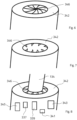
- the clamping device 342 comprises an iris diaphragm 346, which is shown in figure 6 in its closed position and in figure 7 in its opened position.
- An iris diaphragm comprises an arrangement of a circular array of elements having curved edges that are driven in concurrently to form a variable opening. The array of elements is driven circularly around their center to adapt the opening formed by the array of elements.
- the iris diaphragm 346 is closed. As soon as a user intends to wash a vessel, the iris diaphragm 346 is opened as shown in figure 7 . As soon as the user inserted the vessel, the iris diaphragm 346 is partially closes as shown in figure 8 , in which the iris diaphragm 346 clamps the vessel 134.
- the vessel mouth cleaning device 347 has a generally annular shape and a plurality of vessel cleaning nozzles 348 and a plurality of vessel drying nozzles 349 are directed towards a center of the vessel mouth cleaning device 347.
- the vessel 134 is clamped by the iris diaphragm 346 and permeate or gas (such as carbon dioxide) impinges from the plurality of vessel cleaning nozzles 348 on the neck of the vessel 134 and/or gas (such as carbon dioxide) impinges from the plurality of vessel drying nozzles 349 on the neck of the vessel 134.
- the gas may be filtered air or nitrogen.
- the filtered air may be pressurized by a pump (not shown).
- the bottle detection device 370 comprises a positioning area 376, on which a user can position the vessel 134 to be cleaned.
- the vessel 134 comprises an RFID 138 communicating with an antenna 372 of the vessel detection device 370.
- the RFID 138 transmits the vessel type and/or the vessel dimensions to the antenna 372 and a receiver 374 decodes the data received from the RFID 138 and transmits the data to the controller 302.
- the controller 302 may instruct the first input valve 304 to open and instruct the second input valve 320, the first output valve 362 and the second output valve 318 to close. Thereafter, the controller 302 instructs the dispenser controller 136 to deliver permeate via the conduit 152.
- the dispenser controller 136 instructs the pump 106 to pump water through the reverse osmosis filter 106, which is passed by the conduit 108 and the T-valve 150 into the conduit 152.
- the permeate is passed through the first inlet valve 204 and the first inlet 308 into the receptacle 306.
- the receptacle 306 comprises a floater 316 and a floater detection device 317, which may be an optoelectrical sensor for detecting the fill level of permeate in the receptacle 306.
- the controller 302 instructs the first inlet valve 304 to close and instructs the dispenser controller 136 to stop delivering permeate.
- the outer surface of the receptacle 306 may comprise a heating (not shown).
- the floater detection device 317 may comprise a reed switch that detects a magnet in the floater 316.
- the floater detection device 317 may be an ultrasonic sensor detecting the position of the floater 316.
- a first step the user positions the vessel 134 to be cleaned on the positioning area 376 of the vessel detection device.
- the antenna reads the type and/or dimensions and/or shape from the RFID 138 at the vessel 134, a receiver 374 decodes the signals received from the RFID and transmits the data received from the RFID 138 to the controller 302.
- the controller 302 reads data about the shape of the vessel and/or a path, which first swivel element 352 has to pass during cleaning and drying, from a database 303 depending on the type of vessel 134.
- the user removes the vessel 134 from the position and area 376 of the vessel detection device 370.
- the controller instructs the iris diaphragm 346 to open (see figures 6 and 7 ) the user positions the vessel 134 within the clamping device.
- the controller 302 instructs a clamping drive 345 driving the iris diaphragm 346 to clamp the vessel 134.
- a force sensor 343 can detect that the iris diaphragm 346 clamps the bottle.
- the force sensor 343 may be a current sensor monitoring the current to the clamping drive 345.
- the position sensor 341 may be an optoelectronic sensor.
- An optional stop drive 337 may position the stop in an appropriate position depending on the type of vessel 134 and as instructed by the controller 302.
- the controller 302 instructs the second drive 340 to position the first swivel element 352 and the vessel cleaning nozzle 350 juxtaposed to the bottom of the vessel 134 as shown in figure 4 .
- the first swivel element 352, the second swivel element 354 und the third swivel element 353 are arranged in a straight line.
- the controller 302 instructs the second inlet valve 320 and the first outlet valve 362 to open and the first inlet valve 304 and the second outlet valve 318 to close. Further, the neck washer valve 332 is instructed by the controller 302 to open and the heater 334 is instructed to heat permeate passing through it. Then, permeate is urged out of the receptacle 306 into the vessel cleaning conduit 367 by the pressure of carbon dioxide streaming from the gas bottle 324 through the pressure regulator 326 and through the second inlet valve 320 into the receptacle 306. The permeate is ejected by the vessel cleaning nozzle 350 and impinges on an inner surface of the vessel 134.
- the controller 302 instructs the first drive 336 to rotate the rod 336. Thereby, the first swivel element 352 and the vessel cleaning nozzle 350 are rotated. Then, the controller 302 instructs the actuation device 364 to move the string 360 such that the first swivel element 352 and second swivel element 354 are pivoted successively. Simultaneously, the controller 302 instructs the second drive 340 to move the rod 336 successively further towards the bottom of the vessel 134. Thereby, it can be ensured that a very low distance between the vessel cleaning nozzle 350 and the interior wall of the vessel 134 is maintained. The controller 302 continues to instruct the first drive 338 to rotate the rod 336.
- the nozzle 350 passes juxtaposed to the bottom of the vessel 134 in a generally helical path. Permeate continues to flow from the receptacle 306 to the vessel cleaning nozzle 350 and is ejected by the vessel cleaning nozzle 350 on the inner surface of the bottom of the vessel 134. Thereby, the inner surface of the bottom of the vessel 134 is cleaned.
- the controller 302 instructs the actuation device 364 to move the string 360 until the permeate impinges approximately perpendicularly from the vessel cleaning nozzle 350 to the inner surface of the side wall of the vessel 134.
- the controller 302 continues to instruct the first drive 338 to rotate the rod 336.
- the controller 302 instructs the second drive 340 to move the rod 336 successively downwards.
- the vessel cleaning nozzle 350 moves in a generally helical path juxtaposed to the inner surface of the side wall of the vessel 134.
- the controller 302 instructs the actuation device 364 to move the string 360 such that the vessel cleaning nozzle 350 ejects the permeate approximately perpendicular to the shape of the inner wall of the vessel 134.
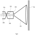
- Figures 3 to 5 show in more detail the position of the first swivel element 352 and the second swivel element 354 during cleaning the interior of the side wall of the vessel 134.
- Figure 5 shows that the vessel cleaning nozzle 350 is formed as a slot ejecting a water beam 351 having a linear shape.
- the controller 302 instructs the actuation means 364 to move the string 360 further downwards such that the permeate impinges approximately perpendicular on the inner surface of the shoulder of the vessel 134.
- the controller 302 instructs the first drive 338 to continue of rotating the rod 336 and the second drive 340 to move the rod downwards.
- the inner surface of the shoulder is cleaned by permeate ejected from the vessel cleaning nozzle 350 passing in a generally helical pattern on the inner surface of the shoulder of the vessel 134.
- the controller 302 instructs the first drive 338 to stop rotating the rod 336, the actuation device to move the string such that the first swivel element 352 and the second swivel element 354 are arranged in a straight line. Thereafter, the controller 302 instructs the second drive 340 to move the rod downwards, such that the first swivel element 352 and the vessel cleaning nozzle 350 are moved out of the neck and mouth of the vessel 134.
- permeate is ejected by a plurality of mouth cleaning nozzles 348 arranged around the mouth of the vessel 134.
- the permeate passes from the receptacle 306 through the first outlet 310, the first outlet valve 362, the heater 334 and the neck washer valve 332 to the plurality of the mouth cleaning nozzles 348.
- the controller instructs the first input valve 304, the second input valve 320 and the first output valve 362 to close and the second outlet valve 318 to open. Thereby, the carbon dioxide in the receptacle 306 is released to the environment and the pressure in the receptacle 306 is reduced. Then, the controller 302 instructs the first inlet valve 304, the second inlet valve 320, the first outlet valve 362 and the second outlet valve 318 to close. Thereafter, the controller instructs the actuation device to move the string 360 such, that the first swivel element 352 and the second swivel element 354 are arranged linearly and instructs the second drive to position the vessel drying nozzle 349 juxtaposed to the bottom wall of the vessel 134.
- the controller 302 instructs the first dryer valve 328 and the second dryer valve 332 to open.
- the pressurized carbon dioxide streams through the first nozzle 350 and the plurality of mouth drying nozzles 349 to dry the interior of the vessel and the mouth of the vessel 134.
- the vessel drying nozzle 349 moves essentially the same path as described above with respect to the cleaning operation.
- the controller 302 opens the iris diaphragm 346 of the vessel clamping device 342 and the user can remove the vessel 134 from the clamping device 342.
- FIG 11 showing a lid 136 clamped by the iris diaphragm 346 of the clamping device.
- the lid 136 can be cleaned and dried as described above with reference to the vessel 134.
- a mobile electronic device 400 such as a smart phone having a camera 402 may take an image of a vessel 134 to be teached for defining the dimensions and shape of the unknown vessel 134 thereafter.
- the image may include a reference object 204, such as a coin or credit card.
- the app determines the dimensions and shape of the unknown vessel 134 by image processing techniques and stores it in a memory of the mobile electronic device 400.
- the path of the first swivel element 252 for cleaning and/or drying the vessel 200 can be determined by the app running on the mobile electronic device 400 based on the shape and dimensions of the vessel to be teached.
- the app running on the personal electronic device 400 programs an RFID 402 of the vessel 200 to be teached to store the dimensions of the vessel 200 to be teached and/or the shape of the vessel 200 to be teached and/or the type of the vessel 200 to be teached and/or the path of the first swivel element 252 in the vessel 200 for cleaning and/or drying the vessel 200 in the RFID 202 of the vessel 200.
- the data of the dimensions and/or the type and/or shape and/or path of the first swivel element 252 in the vessel 200 for cleaning and/or drying the vessel 200 is transmitted by a RFID transmitter 404 of the mobile personal electronic device 400 to the RFID 202 of the vessel 200.
- the app may determine the path of the first swivel element 252 in the vessel 200 for cleaning and/or drying the interior of the vessel 200 by artificial intelligence, such as a neuronal network.
- the app may upload the images to a server, on which a program runs that determines path of the first swivel element 252 in the vessel 200 for cleaning and/or drying the interior of the vessel 200 e.g. by artificial intelligence, such as a neuronal network.
- the Server transmits the path of the first swivel element 252 in the vessel 200 for cleaning and/or drying the interior of the vessel 200 to the app running on the mobile device.
- the vessel recognition device 370 reads the appropriate data from the second RFID 200, namely the type of the vessel 200 and/or the dimensions for cleaning and/or drying the vessel 200 and/or the shape for cleaning and/or drying the vessel 200 and/or the path of the first swivel element 252 in the vessel 200 to be teached for cleaning and/or drying the vessel 200 and transmits it to the controller 302. Thereafter, the controller 302 operates the vessel cleaning apparatus 300 as described above.
- the electronic device 400 takes an image by its camera 402 of the vessel 200 to be teached.
- the image is stored in an app running on the electronic device 400.
- the app determines the path of the first swivel element 252 in the vessel 200 to be teached for cleaning and/or drying the vessel 200 and stores it in a memory of the electronic device.
- the user does not have to position the vessel 200 to be teached on the vessel recognition device 370.
- the data about the type of vessel and/or the dimensions of the vessel 200 and/or the shape of the vessel 200 and/or the path of the first swivel element 252 in the vessel 200 to be teached is transmitted by a second transmitter 406 of the mobile device 400 to a receiver 304 of the bottle cleaning apparatus 300.
- the receiver of the bottle cleaning apparatus 300 transmits the data about the type of vessel 200 and/or the dimensions of the vessel 200 and/or the shape of the vessel 200 and/or the path of the first swivel element 252 in the vessel 200 to be teached to the controller of the bottle cleaning apparatus 300.
- the controller 302 may store the received path of the first swivel element 252 in the vessel 200 to be teached in the database. In another embodiment the controller 302 may determine the path of the first swivel element 252 in the vessel 200 to be teached based on the dimensions of the vessel 200 and/or the shape of the vessel 200 and store it in the database.
- a beverage vessel can be cleaned and dried in a short time span.
- the inventor of the present invention has detected that hot permeate can reliably clean beverage bottles, even if there is a residual coffee, milk, grease or the like in the vessel.
- the vessel cleaning apparatus 300 has the advantage that no cleaning agent causing foam is necessary. Further, the vessel cleaning apparatus 300 according to the present invention needs only a comparatively low amount of demineralized water to clean the beverage vessel.
Landscapes
- Engineering & Computer Science (AREA)
- Mechanical Engineering (AREA)
- Cleaning In General (AREA)
Priority Applications (1)
| Application Number | Priority Date | Filing Date | Title |
|---|---|---|---|
| EP23168779.9A EP4450177A1 (de) | 2023-04-19 | 2023-04-19 | Verbesserte leistung eines getränkespenders |
Applications Claiming Priority (1)
| Application Number | Priority Date | Filing Date | Title |
|---|---|---|---|
| EP23168779.9A EP4450177A1 (de) | 2023-04-19 | 2023-04-19 | Verbesserte leistung eines getränkespenders |
Publications (1)
| Publication Number | Publication Date |
|---|---|
| EP4450177A1 true EP4450177A1 (de) | 2024-10-23 |
Family
ID=86095847
Family Applications (1)
| Application Number | Title | Priority Date | Filing Date |
|---|---|---|---|
| EP23168779.9A Withdrawn EP4450177A1 (de) | 2023-04-19 | 2023-04-19 | Verbesserte leistung eines getränkespenders |
Country Status (1)
| Country | Link |
|---|---|
| EP (1) | EP4450177A1 (de) |
Citations (6)
| Publication number | Priority date | Publication date | Assignee | Title |
|---|---|---|---|---|
| DE4229580A1 (de) | 1992-09-04 | 1994-03-10 | Seitz Enzinger Noll Masch | Verfahren und Vorrichtung zur Überkopf-Behandlung von Flaschen |
| EP0894543A1 (de) | 1997-08-01 | 1999-02-03 | Flavio Rocchi | Verfahren und Maschine zum Spülen oder Sterilisieren von Flaschen mit in die Flaschen eindringende bewegliche Düsen |
| US20090095322A1 (en) * | 2005-05-13 | 2009-04-16 | Yoshitaka Wakao | Container cleaning device, container cleaning method, and tank |
| WO2012040049A2 (en) * | 2010-09-21 | 2012-03-29 | Baker Hughes Incorporated | Minimal entry method and apparatus for cleaning fluid containers |
| EP3489200A1 (de) | 2017-11-23 | 2019-05-29 | Riprup Company S.A. | Vorrichtung zur zugabe von nahrungsergänzungsmitteln, getränkespender mit einer derartigen vorrichtung und methode zur verwendung des getränkespenders |
| EP3932263A2 (de) * | 2020-06-08 | 2022-01-05 | RIPRUP Company S.A. | Verbesserte leistung eines getränkespenders |
-
2023
- 2023-04-19 EP EP23168779.9A patent/EP4450177A1/de not_active Withdrawn
Patent Citations (6)
| Publication number | Priority date | Publication date | Assignee | Title |
|---|---|---|---|---|
| DE4229580A1 (de) | 1992-09-04 | 1994-03-10 | Seitz Enzinger Noll Masch | Verfahren und Vorrichtung zur Überkopf-Behandlung von Flaschen |
| EP0894543A1 (de) | 1997-08-01 | 1999-02-03 | Flavio Rocchi | Verfahren und Maschine zum Spülen oder Sterilisieren von Flaschen mit in die Flaschen eindringende bewegliche Düsen |
| US20090095322A1 (en) * | 2005-05-13 | 2009-04-16 | Yoshitaka Wakao | Container cleaning device, container cleaning method, and tank |
| WO2012040049A2 (en) * | 2010-09-21 | 2012-03-29 | Baker Hughes Incorporated | Minimal entry method and apparatus for cleaning fluid containers |
| EP3489200A1 (de) | 2017-11-23 | 2019-05-29 | Riprup Company S.A. | Vorrichtung zur zugabe von nahrungsergänzungsmitteln, getränkespender mit einer derartigen vorrichtung und methode zur verwendung des getränkespenders |
| EP3932263A2 (de) * | 2020-06-08 | 2022-01-05 | RIPRUP Company S.A. | Verbesserte leistung eines getränkespenders |
Similar Documents
| Publication | Publication Date | Title |
|---|---|---|
| EP3737242B1 (de) | System zur karbonisierung von flüssigkeiten | |
| JP7303232B2 (ja) | 飲料ディスペンスシステムおよび方法 | |
| US11866315B2 (en) | Beverage apparatus and method | |
| US9026245B2 (en) | Container-less custom beverage vending invention | |
| US9986870B2 (en) | Device for providing liquid for a beverage machine and use thereof | |
| CN111629637A (zh) | 具有胶囊识别的饮料制备机器 | |
| US20120234183A1 (en) | Combination concentrate mix and fresh brewed beverage dispensing device | |
| WO2004058020A1 (en) | Clean-in-place automated food or beverage dispenser | |
| CN110996733A (zh) | 用于制备热饮的机器 | |
| US20100083841A1 (en) | Beverage dispensing apparatus | |
| US20210347624A1 (en) | Ultra high ratio liquid delivery system | |
| US4219413A (en) | Method and apparatus for treating water | |
| EP2128080A1 (de) | Verfahren zum waschen einer füllvorrichtung und eines fülltanks | |
| NL8902052A (nl) | Werkwijze en systeem voor het reinigen van een tapinstallatie, houder ten gebruike daarbij en reinigingsmiddel. | |
| US6367655B1 (en) | Apparatus and method for recovering beverage syrup | |
| CN104470354B (zh) | 保持容器、分配装置和保持容器系统 | |
| EP4119013B1 (de) | Getränkezubereitungsmaschine | |
| EP4588883B1 (de) | Getränkeausgabesystem mit reinigungssystem | |
| RU2848491C1 (ru) | Автоматизированная система розлива газированных напитков | |
| KR20210093317A (ko) | 음료 서버의 세정 장치 | |
| EP4480894A1 (de) | Flaschenabfüllvorrichtung und -verfahren | |
| CN223715535U (zh) | 饮品机清洗系统和饮品机设备 | |
| US20240140777A1 (en) | Cleaning assembly for a beverage dispenser | |
| JPH0487990A (ja) | 飲料デイスペンス装置のための自動洗浄方法及び装置 | |
| HK1087311A1 (en) | Self-cleaning mixing head for producing a milk-based mixture and beverage production machines comprising such a mixing head |
Legal Events
| Date | Code | Title | Description |
|---|---|---|---|
| STAA | Information on the status of an ep patent application or granted ep patent |
Free format text: STATUS: UNKNOWN |
|
| PUAI | Public reference made under article 153(3) epc to a published international application that has entered the european phase |
Free format text: ORIGINAL CODE: 0009012 |
|
| STAA | Information on the status of an ep patent application or granted ep patent |
Free format text: STATUS: THE APPLICATION HAS BEEN PUBLISHED |
|
| AK | Designated contracting states |
Kind code of ref document: A1 Designated state(s): AL AT BE BG CH CY CZ DE DK EE ES FI FR GB GR HR HU IE IS IT LI LT LU LV MC ME MK MT NL NO PL PT RO RS SE SI SK SM TR |
|
| STAA | Information on the status of an ep patent application or granted ep patent |
Free format text: STATUS: THE APPLICATION IS DEEMED TO BE WITHDRAWN |
|
| 18D | Application deemed to be withdrawn |
Effective date: 20250424 |