EP4450338A2 - Enrouleur de ceinture - Google Patents
Enrouleur de ceinture Download PDFInfo
- Publication number
- EP4450338A2 EP4450338A2 EP24197372.6A EP24197372A EP4450338A2 EP 4450338 A2 EP4450338 A2 EP 4450338A2 EP 24197372 A EP24197372 A EP 24197372A EP 4450338 A2 EP4450338 A2 EP 4450338A2
- Authority
- EP
- European Patent Office
- Prior art keywords
- belt
- assembly
- reel
- belt reel
- belt retractor
- Prior art date
- Legal status (The legal status is an assumption and is not a legal conclusion. Google has not performed a legal analysis and makes no representation as to the accuracy of the status listed.)
- Pending
Links
Images


Classifications
-
- B—PERFORMING OPERATIONS; TRANSPORTING
- B60—VEHICLES IN GENERAL
- B60R—VEHICLES, VEHICLE FITTINGS, OR VEHICLE PARTS, NOT OTHERWISE PROVIDED FOR
- B60R22/00—Safety belts or body harnesses in vehicles
- B60R22/34—Belt retractors, e.g. reels
-
- B—PERFORMING OPERATIONS; TRANSPORTING
- B60—VEHICLES IN GENERAL
- B60R—VEHICLES, VEHICLE FITTINGS, OR VEHICLE PARTS, NOT OTHERWISE PROVIDED FOR
- B60R22/00—Safety belts or body harnesses in vehicles
- B60R22/18—Anchoring devices
- B60R22/26—Anchoring devices secured to the seat
-
- B—PERFORMING OPERATIONS; TRANSPORTING
- B60—VEHICLES IN GENERAL
- B60R—VEHICLES, VEHICLE FITTINGS, OR VEHICLE PARTS, NOT OTHERWISE PROVIDED FOR
- B60R22/00—Safety belts or body harnesses in vehicles
- B60R22/34—Belt retractors, e.g. reels
- B60R22/341—Belt retractors, e.g. reels comprising energy-absorbing means
- B60R22/3413—Belt retractors, e.g. reels comprising energy-absorbing means operating between belt reel and retractor frame
-
- B—PERFORMING OPERATIONS; TRANSPORTING
- B60—VEHICLES IN GENERAL
- B60R—VEHICLES, VEHICLE FITTINGS, OR VEHICLE PARTS, NOT OTHERWISE PROVIDED FOR
- B60R22/00—Safety belts or body harnesses in vehicles
- B60R22/34—Belt retractors, e.g. reels
- B60R22/44—Belt retractors, e.g. reels with means for reducing belt tension during use under normal conditions
-
- B—PERFORMING OPERATIONS; TRANSPORTING
- B60—VEHICLES IN GENERAL
- B60R—VEHICLES, VEHICLE FITTINGS, OR VEHICLE PARTS, NOT OTHERWISE PROVIDED FOR
- B60R22/00—Safety belts or body harnesses in vehicles
- B60R22/34—Belt retractors, e.g. reels
- B60R22/46—Reels with means to tension the belt in an emergency by forced winding up
-
- B—PERFORMING OPERATIONS; TRANSPORTING
- B60—VEHICLES IN GENERAL
- B60R—VEHICLES, VEHICLE FITTINGS, OR VEHICLE PARTS, NOT OTHERWISE PROVIDED FOR
- B60R22/00—Safety belts or body harnesses in vehicles
- B60R22/34—Belt retractors, e.g. reels
- B60R22/46—Reels with means to tension the belt in an emergency by forced winding up
- B60R22/4628—Reels with means to tension the belt in an emergency by forced winding up characterised by fluid actuators, e.g. pyrotechnic gas generators
-
- B—PERFORMING OPERATIONS; TRANSPORTING
- B60—VEHICLES IN GENERAL
- B60R—VEHICLES, VEHICLE FITTINGS, OR VEHICLE PARTS, NOT OTHERWISE PROVIDED FOR
- B60R22/00—Safety belts or body harnesses in vehicles
- B60R22/28—Safety belts or body harnesses in vehicles incorporating energy-absorbing devices
- B60R2022/286—Safety belts or body harnesses in vehicles incorporating energy-absorbing devices using deformation of material
- B60R2022/287—Safety belts or body harnesses in vehicles incorporating energy-absorbing devices using deformation of material of torsion rods or tubes
-
- B—PERFORMING OPERATIONS; TRANSPORTING
- B60—VEHICLES IN GENERAL
- B60R—VEHICLES, VEHICLE FITTINGS, OR VEHICLE PARTS, NOT OTHERWISE PROVIDED FOR
- B60R22/00—Safety belts or body harnesses in vehicles
- B60R22/34—Belt retractors, e.g. reels
- B60R2022/3402—Retractor casings; Mounting thereof
-
- B—PERFORMING OPERATIONS; TRANSPORTING
- B60—VEHICLES IN GENERAL
- B60R—VEHICLES, VEHICLE FITTINGS, OR VEHICLE PARTS, NOT OTHERWISE PROVIDED FOR
- B60R22/00—Safety belts or body harnesses in vehicles
- B60R22/34—Belt retractors, e.g. reels
- B60R22/44—Belt retractors, e.g. reels with means for reducing belt tension during use under normal conditions
- B60R2022/4473—Belt retractors, e.g. reels with means for reducing belt tension during use under normal conditions using an electric retraction device
-
- B—PERFORMING OPERATIONS; TRANSPORTING
- B60—VEHICLES IN GENERAL
- B60R—VEHICLES, VEHICLE FITTINGS, OR VEHICLE PARTS, NOT OTHERWISE PROVIDED FOR
- B60R22/00—Safety belts or body harnesses in vehicles
- B60R22/34—Belt retractors, e.g. reels
- B60R22/46—Reels with means to tension the belt in an emergency by forced winding up
- B60R22/4628—Reels with means to tension the belt in an emergency by forced winding up characterised by fluid actuators, e.g. pyrotechnic gas generators
- B60R2022/4642—Reels with means to tension the belt in an emergency by forced winding up characterised by fluid actuators, e.g. pyrotechnic gas generators the gas directly propelling a flexible driving means, e.g. a plurality of successive masses, in a tubular chamber
-
- B—PERFORMING OPERATIONS; TRANSPORTING
- B60—VEHICLES IN GENERAL
- B60R—VEHICLES, VEHICLE FITTINGS, OR VEHICLE PARTS, NOT OTHERWISE PROVIDED FOR
- B60R22/00—Safety belts or body harnesses in vehicles
- B60R22/34—Belt retractors, e.g. reels
- B60R22/46—Reels with means to tension the belt in an emergency by forced winding up
- B60R2022/4666—Reels with means to tension the belt in an emergency by forced winding up characterised by electric actuators
Definitions
- the present invention relates to a belt retractor having the features of the preamble of claim 1.
- the basic components of belt retractors are a load-bearing frame and a belt reel that is rotatably mounted in the frame and onto which a safety belt can be wound.
- the frame In addition to supporting the belt reel, the frame is also used to attach it to a seat structure or a vehicle structure and is made from a suitably thick sheet steel that is bent into a U-shaped frame.
- Vehicle seats with safety belt devices are known, for example, for use as front seats in convertibles, where at least the belt retractors of the safety belt devices are attached to the backrests of the vehicle seats.
- the belt retractors are preferably integrated into the backrests of the vehicle seats due to the lack of a load-bearing B-pillar and for reasons of access to the rear seats or for reasons of distance from the rear vehicle structure, which must therefore also be designed to absorb the tensile forces acting in the event of a restraint.
- the belt retractors themselves have all the basic components of a standard belt retractor and are only provided with various additional components specifically designed for installation in the backrest, such as a self-aligning inertia sensor.
- the basic design of the vehicle seat comprises a seat structure made up of several load-bearing structural parts which serve to attach the vehicle seat to the vehicle structure.
- the seat structure is provided with springs and padding to improve seating comfort and also serves to attach other components such as various seat adjustment mechanisms, including the associated electric motors and other components such as heaters, sensors, displays, headrests and the like.
- the belt retractor and its other components require a relatively large amount of space due to their external dimensions, so that installation in the vehicle seat can be problematic. This is particularly due to the fact that the seat belt must have a certain minimum thickness to absorb the tensile forces with a given width of e.g. 46 mm and a certain minimum length of e.g. 2500 mm to restrain the occupant, so that the belt wrap on the belt reel has a correspondingly large external diameter when the seat belt is fully wound up due to the volume of the seat belt to be wound up.
- This large belt wrap is supported by a correspondingly large frame of the belt retractor and by other components such as a drive device for an irreversible belt tensioner, an electric motor for a reversible belt tensioner.
- belt tensioner, a force limiting device, sensor devices or the like is further enlarged towards the outside, thereby further increasing the installation space requirement.
- the object of the invention is to provide a belt retractor which can also be arranged in a limited installation space of a vehicle seat.
- a belt retractor with a belt reel, a safety belt that can be wound up on it to form a belt reel and at least one first assembly in which the further assembly is arranged coaxially and in series with the belt reel, the belt retractor is mounted on a first web arranged between the belt reel and the first assembly, and at least one second web is provided for mounting the belt retractor, which is spaced from the first web in the axial direction of the belt retractor, a profile rail that is U-shaped in cross section with a base surface and two opposite, parallel, wall-shaped legs that protrude from the base surface, with an opening formed between the edge sides of the legs, which is closed by an insert part, wherein the insert part closes a cavity formed between the legs, in which the belt reel and the first assembly are arranged, wherein the webs are supported in a rotationally fixed manner between the legs, wherein a second assembly is provided, which is coaxially and is arranged in series with the belt spool (14)
- the proposed solution enables the belt retractor to be arranged in a space-saving design in a narrow, elongated installation space on the vehicle seat.
- the first assembly is deliberately arranged in a coaxial orientation in series with the belt spool so that an elongated geometry of the belt retractor can be realized. Since the first assembly is arranged in series with the belt spool, ie behind or in front of the belt spool in relation to the longitudinal direction of the axis of rotation of the belt spool, the first assembly can be arranged such that it only projects slightly, if at all, beyond the belt reel towards the outside.
- the assembly can be, for example, a reversible belt tensioner, an irreversible belt tensioner, a force limiting device, a sensor device or even a control device. If further assemblies are provided, these assemblies are preferably arranged in series, i.e. one behind the other, in relation to the axis of rotation of the belt reel, whereby the elongated design of the belt retractor is continued and further extended.
- the belt retractor is mounted in one or more webs arranged between an assembly and the belt reel or between two assemblies.
- the web can also The web can be used to accommodate additional functional units, such as sensors, gas generators, control units or the like.
- the web can also be used to stiffen the load-bearing structural part.
- the web enables the belt retractor to be shaped in an elongated manner with components arranged in a row.
- At least one second web is provided which is spaced apart from the first web.
- the second web can further improve the bearing of the belt retractor and further assemblies and functional units can be provided, e.g. for the further assemblies of the belt retractor.
- a second assembly is provided which is arranged coaxially and in series with the belt reel and the first assembly.
- the second assembly can provide the belt retractor with additional functions, with the belt reel and the first assembly remaining unchanged at least in their basic structure.
- the belt retractor can therefore have a modular structure which, thanks to its modular structure, can be provided with various functions specific to the customer and application.
- the second web can preferably be arranged between the first assembly and the second assembly, so that it serves as a bearing point for two assemblies at the same time.
- the first or second assembly is formed by a force limiting device with a first torsion bar arranged coaxially to the belt reel.
- the proposed solution allows the belt retractor to be a design that is as narrow and compact as possible with a particularly simple construction.
- the further assembly has smaller or identical external dimensions in the direction perpendicular to the axis of rotation of the belt reel than the maximum external diameter of the belt reel when the seat belt is completely wound onto the belt reel.
- the belt reel is circular in cross-section and in the embodiments provided is arranged in a cavity with a square cross-section, the cavities for accommodating the belt retractor have a square cross-section with side lengths corresponding at least to the diameter of the maximum belt reel. This results in approximately triangular, elongated free spaces in the corners, which can of course also be used. Such a projection into these free spaces should also be understood in the sense of the invention as being within the external dimensions specified by the maximum diameter of the belt reel.
- the maximum external dimensions of the belt retractor are determined by the fully wound belt coil with a maximum external diameter, which cannot be reduced anyway for the reasons mentioned above.
- the belt retractor can be designed to be as narrow as possible, so that it can also be arranged in elongated, narrow spaces in the vehicle seat or other structures of a vehicle. If the belt retractor is attached in a cavity of a load-bearing structural part of the vehicle or the vehicle seat, this can also replace the previously required frame of the belt retractor, in that the belt spool of the belt retractor is held and mounted directly on the load-bearing structural part.
- the occurring tensile forces are introduced directly into the structural part, whereby the load-bearing structural part can be specifically designed to absorb the restraining forces through the shape of the hollow space.
- the load-bearing structural part is a structural part of the seat structure, it is already designed to absorb seat forces and other forces acting on the vehicle seat and therefore already has a sufficiently high level of strength, which can also be used by the proposed solution to absorb the restraining forces exerted by the seat belt.
- the load-bearing structural part has a particularly high torsional and flexural rigidity due to the hollow space provided and the three-dimensional design resulting from it, which in turn is advantageous for load bearing and restraining the occupant in the event of an accident.
- the first or the second assembly is a pyrotechnic belt tensioner, which has a tensioner drive tube with a pyrotechnically drivable drive device provided therein and a drive wheel that transmits the drive movement of the drive device to the belt reel, wherein the tensioner drive tube has a linear section and a curved section arranged at the end of the linear section, and the tensioner drive tube is arranged such that the linear section runs parallel to the axis of rotation of the belt reel and is directed with the curved section tangentially in the circumferential direction towards the drive wheel.
- the advantage of the proposed design of the pyrotechnic belt tensioner is that it can be made particularly compact with the proposed shape and arrangement of the tensioner drive tube, wherein the tensioner drive tube is preferably formed into a edge-side linear free space on the belt retractor, whereby the external dimensions of the belt retractor are only slightly increased, if at all.
- the force limiting device can have at least one second torsion bar, which is arranged in series with the first torsion bar.
- the second torsion bar can be used to implement the force limiting level with different force limiting levels depending on the dimensioning of the two torsion bars, whereby the coaxial arrangement in turn enables a compact, slim design of the belt retractor to be implemented.
- a tubular extension is provided on one end of the belt reel, arranged coaxially to the axis of rotation of the belt reel, into which the first and/or the second torsion bar extends.
- the extension extends the belt reel axially and creates a bearing attachment for a blocking part that can be blocked via a blocking device, to which the first and/or the second torsion bar is connected or can be connected via a coupling.
- the torsion bar is in turn connected either directly to the belt reel or via the extension in a rotationally fixed manner, so that when the blocking part is blocked and a defined belt webbing pull-out force is exceeded, it begins to plastically deform around its own longitudinal axis and thus dissipates the energy.
- the belt retractor is mounted with the tubular extension on the first and/or the second web.
- the extension is thus additionally mounted the belt reel, which is particularly advantageous during the plastic deformation of the torsion bar(s), since the forces to be absorbed by the bearing can be absorbed as close as possible to their point of origin and the resulting torques in the bearing can be kept small.
- first or the second or a third assembly is formed by a reversible belt tensioner with an electric motor, wherein the electric motor with its protruding drive shaft is arranged coaxially to the axis of rotation of the belt reel.
- a part of a seat structure of a vehicle seat for a motor vehicle can be seen, which forms the backrest of the vehicle seat.
- the seat structure forms the dimensionally stable "core" of the vehicle seat and is additionally provided with springs and/or padding to improve seating comfort.
- other functional components not shown are provided on the seat structure, such as seat adjustment mechanisms, a headrest, electronic devices such as displays, or heating devices.
- the seat structure comprises a composite of several load-bearing structural parts 2, two of which are formed by longitudinal struts 1 aligned parallel to one another.
- the upper ends of the longitudinal struts 1 are connected to one another by a load-bearing structural part 2 to form a dimensionally stable upper side of the backrest.
- raised tabs 4 with fastening openings are provided on them, and fastening openings are also provided on the structural part 2, through which the parts are connected to one another either by screws or rivets.
- the load-bearing structural part 2 can be seen in an enlarged view as an individual part.
- the load-bearing structural part 2 comprises as a basic component a profile rail 7 which is U-shaped in cross-section, with a base surface 10 and two opposite, parallel to each other, wall-shaped legs 8 and 9 which protrude from the base surface 10.
- the profile rail 7 has an opening 28 formed between the edge sides of the legs 8 and 9, which is closed by a Figure 1 to be recognized insert part 6 is closed, but that in the Figure 2 has been omitted for better recognition of the structural part 2.
- the insert part 6 is formed by a plate with a shape adapted to the opening 28 adapted shape and has a slot 13 through which a safety belt 12, described in more detail below, is guided from a cavity 21 between the legs 8 and 9 to the outside onto an occupant to be restrained on the vehicle seat.
- the insert part 6 closes or reduces the opening 28 except for the slot 13 provided, so that the cavity 21 is closed to the outside and a belt retractor 40 according to the invention provided therein is protected from mechanical effects.
- the end faces of the profile rail 7 are each closed by a web 15 and 20.
- the belt retractor 40 is arranged with a belt reel 14 and the safety belt 12 which can be wound on it, which in the Figure 3 can be seen in a sectional view.
- the belt retractor 40 has a further assembly or first assembly in the form of a force limiting device 25 with several torsion bars 26, 36 and 37, a second assembly in the form of a pyrotechnic irreversible belt tensioner 24 and a third assembly in the form of a reversible electromotive belt tensioner 23 in a coaxial arrangement to the axis of rotation of the belt reel 14.
- the assemblies are arranged in series, one behind the other to the belt reel 14.
- the external dimensions of the belt reel 14 with the safety belt 12 wound up to the maximum, as well as the external dimensions of the force limiting device 25, the pyrotechnic belt tensioner 24 and the electromotive belt tensioner 23 are selected in the cross-sectional area perpendicular to the axis of rotation of the belt reel 14 so that they are not larger than the external dimensions of the belt winding on the belt reel 14 with the safety belt 12 wound up to the maximum. Furthermore, the external dimensions are not larger than the dimensions of the cavity 21 are perpendicular to the longitudinal extension of the profile rail 7, so that the belt retractor 40 with the assemblies can be arranged in the cavity 21 of the profile rail 7.
- the profile rail 7 several webs 15, 16, 17, 18, 19 and 20 are provided in the form of wall sections aligned perpendicular to the longitudinal extent of the profile rail 7, which extend from one of the legs 8 or 9 to the other leg 8 or 9 of the profile rail 7 and are connected to them. Furthermore, the webs 15, 16, 17, 18, 19 and 20 can extend to the base surface 10 of the profile rail 7 and thus fill the entire cross-sectional area of the profile rail 7.
- the webs 15, 16, 17, 18, 19 and 20 each have one or more openings or projections in which the belt retractor 40 or parts thereof such as the belt reel 14 are mounted, fastened and/or guided through.
- one of the webs 15, 16, 17, 18, 19 and 20 can also have a toothing or another type of blocking design in which the belt reel 14 or other parts of the belt retractor can be blocked.
- the webs 15, 16, 17, 18, 19 and 20 can also have additional cavities for accommodating other components of the belt retractor, such as pyrotechnic propellants for the pyrotechnic belt tensioner 24, electronic components such as sensors, electronic control units or memory units. If the webs 15, 16, 17, 18, 19 and 20 extend from one of the legs 8 or 9 to the other leg 8 or 9, the webs 15, 16, 17, 18, 19 and 20 can also be used to stiffen the profile rail 7, which in turn is advantageous for the load bearing and the dimensional stability of the profile rail 7 in the event of the occupant being restrained.
- the components of the belt retractor 40 are deliberately arranged coaxially and one behind the other, so that the assemblies radially cover the external dimensions of the belt retractor. not increase outwards, and the belt retractor 40 can also be arranged in a narrow, elongated cavity 21 of the profile rail 7.
- the profile rail 7 and the load-bearing structural part can be designed to be correspondingly narrow and elongated, which is particularly advantageous for using the load-bearing structural part in a seat structure of the vehicle seat.
- the load-bearing structural part can be seen in a section through the profile rail 7 and the belt retractor.
- the profile rail 7, which is U-shaped in cross section, has the legs 8 and 9 facing the viewer in this illustration and a base surface 10.
- the cavity 21, in which the belt retractor 40 is arranged, is provided between the legs 8 and 9.
- the cavity 21 is divided by six webs 15, 16, 17, 18, 19 and 20 in the longitudinal direction of the profile rail 7, with the two outer webs 15 and 20 closing the cavity 21 to the outside at the two ends of the profile rail 7.
- a spring cassette with a mainspring 27 is held on the right web 15, which in turn is connected to the belt spool 14 and thereby pre-tensions the belt spool 14 in the winding direction of the safety belt 12 wound on it.
- the belt reel 14 is provided at its end protruding into the profile rail 7 with a force limiting device 25, which is formed by a tubular extension 38 of the belt reel 14 arranged coaxially to the belt reel 14, three torsion bars 26, 36 and 37 arranged in series and a blocking part 41 which can be locked in a rotationally fixed manner relative to the profile rail 7.
- a force limiting device 25 which is formed by a tubular extension 38 of the belt reel 14 arranged coaxially to the belt reel 14, three torsion bars 26, 36 and 37 arranged in series and a blocking part 41 which can be locked in a rotationally fixed manner relative to the profile rail 7.
- three torsion bars 26, 36 and 37 are provided, each of which is or can be locked in a rotationally fixed manner at one end to the belt reel 14 or to the tubular extension 38 and is connected to the other end by a
- the switching device provided on web 16 or 17 can be blocked in a rotationally fixed manner relative to the profile rail 7 or can be released from it.
- the torsion bars 26, 36 and 37 can therefore be activated individually or in combination, whereby the restraining forces can be achieved at different force limiting levels or a stepped force limiting course.
- the blocking part 41 can be blocked in the extension direction of the seat belt 12 by a blocking device that can be controlled in a vehicle-sensitive and/or belt-sensitive manner, whereby the force limiting device 25 is blocked so that it is subsequently activated automatically when the force limiting level defined by the force limiting device 25 itself is exceeded.
- a pyrotechnic, irreversible belt tensioner 24 is provided with a drive wheel 35 arranged coaxially to the belt spool 14, which drives the belt spool 14 in the winding direction via an intermediate clutch when activated and tightens the seat belt 12.
- a reversible belt tensioner 23 with an electric motor 22 which drives the belt reel 14 in the winding direction when activated via a second or the same coupling as the pyrotechnic belt tensioner 24 and thereby tightens the seat belt 12.
- the electric motor 22 is also arranged coaxially to the belt reel 14 and thus also to the force limiting device 25 and to the pyrotechnic belt tensioner 24.
- an electronic control unit 29 is provided in the profile rail 7 of the load-bearing structural part 2, which can be used to control the belt retractor 40 and/or other components.
- the load-bearing structural part 2 is a basic component of the seat structure, in that it supports other parts of the seat structure such as the Figure 1 longitudinal struts 1 which can be seen.
- the structural part 2 thus has the task of forming the seat structure and, through the provided cavity 21, also serves to accommodate the belt retractor 40 according to the invention.
- the load-bearing structural part 2 can be pre-assembled as an assembly with the belt retractor 40 and then finally assembled as a structural unit during the manufacture of the seat structure or the vehicle seat.
- the profile rail 7 forms the basic component of the load-bearing structural part 2 and is shaped and dimensioned according to the connection to be made between the other structural parts in the seat structure.
- the profile rail 7 can replace the previously required frame of the belt retractor 40 by serving both for supporting the belt retractor 40 and for fastening the belt retractor 40 to the vehicle seat and for blocking the belt reel 14.
- the belt retractor 40 is designed in a modular manner with the belt reel 14 and the other components, namely the force limiting device 25, the pyrotechnic belt tensioner 24 and the reversible belt tensioner 23 in a coaxial series arrangement.
- the components are deliberately designed in such a way that their radial outer dimensions do not exceed the dimensions of the belt winding on the belt reel 14 when the seat belt 12 is wound up to the maximum, as shown in the Figure 3 can be recognized.
- the webs 15, 16, 17, 18, 19 and 20 can also be understood as functional walls by providing appropriate supports and arranging various functional units in or on the supports.
- the webs 15, 16, 17, 18, 19 and 20 are supported preferably between the legs 8 and 9 and the base surface 10 of the profile rail 7 or between the Figure 4
- the housing parts 30 and 31 can be seen in a rotationally fixed manner.
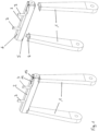
- the belt retractor 40 according to the invention is provided with a two-part housing with two housing parts 30 and 31 instead of a profile rail 7.
- the housing parts 30 and 31 are each U-shaped and comprise the belt reel 14 and the other components, including the webs 15, 16, 17, 18, 19 and 20 in the mounted position on the outside, as in the upper right illustration of the Figure 4 can be seen.
- the housing parts 30 and 31 form an elongated cavity 21 with a square cross-section.
- the tensioner drive tube 32 serves to guide a drive device, such as a chain of loosely adjacent mass bodies, or an elastic drive train, which is accelerated when the pyrotechnic belt tensioner is activated and is thereby brought into driving connection with the drive wheel 35.
- the drive wheel 35 and the belt spool 14 are thereby subsequently driven to rotate in the winding direction of the safety belt 12.
- the tensioner drive tube 32 has a linear section 33 and a curved section 34 and is aligned and arranged such that it is aligned with the linear section 33 parallel to the axis of rotation of the belt reel 14 and the drive wheel 35. and is directed with the curved section 34 tangentially in the circumferential direction towards the outer circumference of the drive wheel 35.
- the curved section 34 is curved exclusively in one plane, so that the curved section 34 and the linear section 33 are arranged in one plane, wherein the tensioner drive tube 32 is aligned such that the plane spanned by the linear section 33 and the curved section 34 runs parallel to the axis of rotation of the belt reel 14.
- the housing parts 30 and 31 form a dimensionally stable part with the belt retractor 40 arranged therein, which is used as the Figure 1 load-bearing structural part 2 can be used in the seat structure.
- the load-bearing structural part 2 with the profile rail 7 or the housing parts 30 and 31 was assembled as shown in the Figure 1 in a horizontal installation geometry, which has advantages with regard to a horizontal alignment of the safety belt 12 in the feed to the occupant.
- a horizontal alignment of the safety belt 12 in the feed to the occupant is advantageous in that the safety belt 12 can thus be guided horizontally onto the occupant's shoulder without being redirected again.
- the load-bearing structural part 2 can also be arranged in a vertical or oblique alignment on the seat structure. The safety belt 12 is then fed in an oblique alignment or redirected to the occupant in the intended feed direction by means of a separate deflection device.
- the structural part 2 can also be arranged at a lower point or on one side of the seat structure instead of at an upper edge of the backrest. Backrest, provided that the seat structure or the supply of the safety belt 12 requires and/or allows this.
- the profile rail 7 or the housing parts 30 and 31 it would also be conceivable to provide a tubular structural part 2 with a circular or other type of cross-section, in which the belt retractor 40 is arranged and in particular inserted at the front.
Landscapes
- Engineering & Computer Science (AREA)
- Mechanical Engineering (AREA)
- Automotive Seat Belt Assembly (AREA)
- Seats For Vehicles (AREA)
- Emergency Lowering Means (AREA)
Applications Claiming Priority (4)
| Application Number | Priority Date | Filing Date | Title |
|---|---|---|---|
| DE102018213282.8A DE102018213282A1 (de) | 2018-08-08 | 2018-08-08 | Gurtaufroller |
| PCT/EP2019/071200 WO2020030685A1 (fr) | 2018-08-08 | 2019-08-07 | Rétracteur de ceinture |
| EP19755846.3A EP3833583B1 (fr) | 2018-08-08 | 2019-08-07 | Enrouleur de ceinture |
| EP21201466.6A EP3964407A1 (fr) | 2018-08-08 | 2019-08-07 | Enrouleur de ceinture |
Related Parent Applications (2)
| Application Number | Title | Priority Date | Filing Date |
|---|---|---|---|
| EP19755846.3A Division EP3833583B1 (fr) | 2018-08-08 | 2019-08-07 | Enrouleur de ceinture |
| EP21201466.6A Division EP3964407A1 (fr) | 2018-08-08 | 2019-08-07 | Enrouleur de ceinture |
Publications (2)
| Publication Number | Publication Date |
|---|---|
| EP4450338A2 true EP4450338A2 (fr) | 2024-10-23 |
| EP4450338A3 EP4450338A3 (fr) | 2025-01-08 |
Family
ID=67667820
Family Applications (4)
| Application Number | Title | Priority Date | Filing Date |
|---|---|---|---|
| EP19755846.3A Active EP3833583B1 (fr) | 2018-08-08 | 2019-08-07 | Enrouleur de ceinture |
| EP21201465.8A Pending EP3964406A1 (fr) | 2018-08-08 | 2019-08-07 | Enrouleur de ceinture |
| EP24197372.6A Pending EP4450338A3 (fr) | 2018-08-08 | 2019-08-07 | Enrouleur de ceinture |
| EP21201466.6A Pending EP3964407A1 (fr) | 2018-08-08 | 2019-08-07 | Enrouleur de ceinture |
Family Applications Before (2)
| Application Number | Title | Priority Date | Filing Date |
|---|---|---|---|
| EP19755846.3A Active EP3833583B1 (fr) | 2018-08-08 | 2019-08-07 | Enrouleur de ceinture |
| EP21201465.8A Pending EP3964406A1 (fr) | 2018-08-08 | 2019-08-07 | Enrouleur de ceinture |
Family Applications After (1)
| Application Number | Title | Priority Date | Filing Date |
|---|---|---|---|
| EP21201466.6A Pending EP3964407A1 (fr) | 2018-08-08 | 2019-08-07 | Enrouleur de ceinture |
Country Status (7)
| Country | Link |
|---|---|
| US (2) | US20200047711A1 (fr) |
| EP (4) | EP3833583B1 (fr) |
| JP (3) | JP7087189B2 (fr) |
| KR (1) | KR102502956B1 (fr) |
| CN (2) | CN116409282A (fr) |
| DE (1) | DE102018213282A1 (fr) |
| WO (1) | WO2020030685A1 (fr) |
Families Citing this family (12)
| Publication number | Priority date | Publication date | Assignee | Title |
|---|---|---|---|---|
| EP4144597B1 (fr) * | 2018-10-22 | 2025-02-26 | Adient US LLC | Structure de siège de véhicule et procédé de montage d'une structure de siège de véhicule |
| DE102018218293A1 (de) * | 2018-10-25 | 2020-04-30 | Autoliv Development Ab | Gurtaufroller |
| DE102019218306A1 (de) * | 2019-11-26 | 2021-05-27 | Autoliv Development Ab | Gurtaufroller |
| DE102019218307A1 (de) * | 2019-11-26 | 2021-05-27 | Autoliv Development Ab | Gurtaufroller |
| DE102020211209A1 (de) * | 2020-09-07 | 2022-03-10 | Autoliv Development Ab | Gurtaufroller |
| DE102020211208A1 (de) | 2020-09-07 | 2022-03-10 | Autoliv Development Ab | Gurtaufroller |
| DE102020133790B4 (de) * | 2020-12-16 | 2025-12-31 | Autoliv Development Ab | Gurtstraffer für ein Sicherheitsgurtsystem eines Kraftfahrzeugs |
| DE102021105010B4 (de) * | 2021-03-02 | 2023-02-23 | Autoliv Development Ab | Lasttragender Gurtaufroller und Sitzstruktur |
| DE102021105013A1 (de) * | 2021-03-02 | 2022-09-08 | Autoliv Development Ab | Lasttragender Gurtaufroller |
| KR102715416B1 (ko) * | 2022-03-30 | 2024-10-11 | 아우토리브 디벨롭먼트 아베 | 프리 텐셔닝 모듈 및 그가 적용된 시트벨트 리트랙터 |
| DE102022132184A1 (de) * | 2022-12-05 | 2024-06-06 | Autoliv Development Ab | Gurtaufroller und Fahrzeugsitz |
| KR20250001311A (ko) * | 2023-06-28 | 2025-01-06 | 현대자동차주식회사 | 차량용 시트 |
Family Cites Families (76)
| Publication number | Priority date | Publication date | Assignee | Title |
|---|---|---|---|---|
| US2899146A (en) * | 1959-08-11 | barecki | ||
| US2825581A (en) * | 1956-06-29 | 1958-03-04 | Gilbert L Knight | Safety shoulder and lap belt device for motor vehicle passengers |
| FR1231466A (fr) * | 1958-12-17 | 1960-09-29 | Talco Engineering Company | Perfectionnements aux dispositifs de retenue et de tension pour bretelles de sécurité pour aviateurs et autres |
| US3096957A (en) * | 1960-11-03 | 1963-07-09 | Leslie D Peterson | Ballistic rotary actuator |
| DE1260991B (de) * | 1962-06-14 | 1968-02-08 | Teleflex Prod Ltd | Sperrvorrichtung fuer die Aufwickelrolle eines Sicherheitsgurtes |
| GB1212013A (en) * | 1967-03-20 | 1970-11-11 | Teleflex Prod Ltd | Improvements in or relating to safety harness reels |
| JPS5723359U (fr) * | 1980-07-15 | 1982-02-06 | ||
| JPS6049056U (ja) | 1983-09-13 | 1985-04-06 | 株式会社東海理化電機製作所 | ウエビング巻取装置 |
| JPS60124768U (ja) | 1984-01-30 | 1985-08-22 | 株式会社東海理化電機製作所 | ウエビング緊張装置 |
| US4568106A (en) | 1984-04-30 | 1986-02-04 | Tachikawa Spring Co., Ltd. | Passive restraint for a vehicle seat |
| DE3636912C2 (de) | 1986-10-30 | 1994-02-17 | Keiper Recaro Gmbh Co | Rückenlehne für einen Fahrzeugsitz |
| US5253924A (en) | 1991-06-11 | 1993-10-19 | Concept Analysis Corporation | Blow molded seat back with integral reinforcing member |
| DE9301827U1 (de) * | 1993-02-10 | 1993-05-13 | Griesemer, Albert, 5438 Westerburg | Schutzrohr für Gurtstraffer |
| US5924640A (en) * | 1995-02-16 | 1999-07-20 | Royal Ordnance Public Limited Company | Vehicle occupant restraint system |
| DE19616016C2 (de) * | 1996-04-23 | 2000-08-10 | Schroth Gmbh Carl F | Halterung für einen Schultergurt eines Sicherheitsgurts |
| JPH10117486A (ja) * | 1996-10-11 | 1998-05-06 | Takata Kk | 超音波モータ及びシートベルトリトラクタ |
| US5697670A (en) | 1996-11-12 | 1997-12-16 | Hoover Universal, Inc. | Vehicle seat |
| SE514382C2 (sv) * | 1998-05-20 | 2001-02-19 | Saab Automobile | Sätt och anordning vid ett säkerhetsbälte |
| JP2000198417A (ja) | 1998-11-06 | 2000-07-18 | Takata Corp | 乗員拘束保護システムにおけるモニタシステム |
| DE19959956A1 (de) * | 1999-12-13 | 2001-06-21 | Breed Automotive Tech | Gurtaufroller |
| DE10013869C2 (de) | 2000-03-21 | 2002-06-20 | Breed Automotive Tech | Komfort-Aufwickeleinrichtung für einen Sicherheitsgurt mit Motorrückholung |
| JP4811893B2 (ja) | 2000-04-21 | 2011-11-09 | タカタ株式会社 | モータ式シートベルトリトラクター |
| EP1280684B1 (fr) * | 2000-05-10 | 2005-08-31 | Autoliv Development Ab | Enrouleur de ceinture de securite a tendeur reversible |
| US6726249B2 (en) | 2000-05-26 | 2004-04-27 | Takata Corporation | Motorized seat belt retractor |
| US20020140278A1 (en) | 2001-03-19 | 2002-10-03 | Hlavaty David Gerard | Seat restraint tensioner |
| JP4669143B2 (ja) | 2001-03-19 | 2011-04-13 | タカタ株式会社 | モータリトラクタシステム |
| DE10122910B4 (de) * | 2001-05-11 | 2004-10-21 | Breed Automotive Technology, Inc., Lakeland | Rückhaltevorrichtung für einen Fahrzeuginsassen |
| DE10204477B4 (de) * | 2002-02-05 | 2006-11-30 | Daimlerchrysler Ag | Gurtstraffer |
| DE10204476A1 (de) * | 2002-02-05 | 2003-08-21 | Daimler Chrysler Ag | Gurtstraffer |
| ATE375901T1 (de) * | 2002-05-29 | 2007-11-15 | Autoliv Dev | Sicherheitsgurtaufroller mit einer vorstraffeinrichtung |
| US20130256445A1 (en) | 2002-05-29 | 2013-10-03 | Autoliv Development Ab | Safety belt retractor having a pretensioning device |
| DE10354071A1 (de) * | 2003-11-19 | 2005-06-09 | Daimlerchrysler Ag | Gurtroller für ein Sicherheitsgurtsystem |
| US7475941B2 (en) | 2004-05-28 | 2009-01-13 | Skjp Holdings Llc | Compact folding seat with reverse cantilevered pivot |
| DE202004009949U1 (de) * | 2004-06-24 | 2004-10-14 | Key Safety Systems, Inc., Lakeland | Aufwickelvorrichtung für einen Sicherheitsgurt eines Fahrzeugs |
| DE102004048455B4 (de) * | 2004-10-05 | 2009-01-08 | Fraunhofer-Gesellschaft zur Förderung der angewandten Forschung e.V. | Vorrichtung und Verfahren zur Straffung eines zum Insassenschutz in einem Fahrzeug dienenden Sicherheitsgurtes |
| US8480180B2 (en) | 2005-01-04 | 2013-07-09 | Isringhausen Gmbh & Co. Kg | Height-adjustable deflection device for a three-point belt, vehicle seat with a three-point belt and method for the height adjustment of the upper fastening point of a three-point belt |
| DE102005012623A1 (de) | 2005-03-18 | 2006-09-21 | Siemens Ag | Schraubradgetriebeeinheit |
| DE102005014521B4 (de) * | 2005-03-30 | 2007-12-06 | Siemens Restraint Systems Gmbh | Insassenschutzsystem in einem Verkehrsmittel, insbesondere in einem Kraftfahrzeug |
| JP4612519B2 (ja) | 2005-10-11 | 2011-01-12 | 三菱自動車工業株式会社 | リクライニングシートの構造 |
| US20070194565A1 (en) | 2006-02-21 | 2007-08-23 | Autoliv Asp, Inc. | Device for and a method of controlling tension of a vehicle seatbelt |
| DE102006010268B4 (de) | 2006-03-02 | 2009-03-05 | Zf Friedrichshafen Ag | Schraubradgetriebe für Zahnstangenlenkung |
| DE102006026734B4 (de) | 2006-06-08 | 2008-09-04 | Siemens Ag | Gurtstrafferantrieb |
| JP5121213B2 (ja) | 2006-11-22 | 2013-01-16 | タカタ株式会社 | シートベルト装置 |
| JP4953835B2 (ja) | 2007-01-17 | 2012-06-13 | オートリブ ディベロップメント エービー | シートベルト用リトラクタ |
| US20080246316A1 (en) | 2007-04-03 | 2008-10-09 | David Shaun Carine | Child restraint system including tension sensor and status indicator |
| JP5126575B2 (ja) | 2007-05-01 | 2013-01-23 | オートリブ ディベロップメント エービー | ウェビング巻取り装置 |
| JP5171121B2 (ja) | 2007-06-20 | 2013-03-27 | タカタ株式会社 | プリテンショナ及びシートベルト装置 |
| DE102007038916A1 (de) | 2007-08-17 | 2009-02-26 | Continental Automotive Gmbh | Gurtstrafferantrieb für den Sicherheitsgurt eines Fahrzeugs mit einem Topflager für die Rotorwelle eines Elektromotors |
| DE102008045999A1 (de) | 2007-12-10 | 2009-06-18 | C. Rob. Hammerstein Gmbh & Co. Kg | Kraftfahrzeugsitz mit einer Rückenlehne und einer Gurtumlenkung |
| GB0724215D0 (en) | 2007-12-12 | 2008-01-23 | Norgren Ltd C A | Seat belt device |
| WO2009123314A1 (fr) | 2008-04-04 | 2009-10-08 | オートリブ ディベロップメント エービー | Rétracteur de ceinture de sécurité |
| DE102008040673B4 (de) | 2008-06-24 | 2018-07-26 | Robert Bosch Automotive Steering Gmbh | Wellenlagerung in einem Lenksystem und damit ausgestattetes Lenkgetriebe und Herstellungsverfahren dafür |
| DE102008048339B4 (de) | 2008-09-22 | 2016-07-28 | Autoliv Development Ab | Reversibler Gurtstraffer |
| JP5434102B2 (ja) | 2009-01-29 | 2014-03-05 | アイシン精機株式会社 | 車両用シートスライド装置 |
| DE102009035047A1 (de) * | 2009-07-28 | 2011-02-03 | Autoliv Development Ab | Selbstsperrender Gurtaufroller |
| KR101377193B1 (ko) | 2009-11-04 | 2014-03-25 | 오토리브 디벨로프먼트 에이비 | 시트 벨트용 리트랙터 |
| US8220735B2 (en) * | 2009-12-22 | 2012-07-17 | Autoliv Asp, Inc. | Adaptive load limiting retractor |
| JP5662029B2 (ja) | 2010-01-22 | 2015-01-28 | 日鉄住金精圧品株式会社 | トーションバー |
| DE102010053175B4 (de) * | 2010-12-03 | 2017-01-19 | Autoliv Development Ab | Airbageinrichtung |
| KR101252222B1 (ko) * | 2011-10-31 | 2013-04-05 | 현대자동차주식회사 | 차량의 로드리미터 |
| JP2013244882A (ja) | 2012-05-28 | 2013-12-09 | Ashimori Industry Co Ltd | シートベルト用リトラクタ |
| JP5576453B2 (ja) | 2012-10-16 | 2014-08-20 | 本田技研工業株式会社 | シートベルト装置 |
| JP5602253B2 (ja) | 2013-01-09 | 2014-10-08 | 本田技研工業株式会社 | シートベルト装置 |
| DE102013011267A1 (de) * | 2013-07-05 | 2015-01-08 | GM Global Technology Operations LLC (n. d. Gesetzen des Staates Delaware) | Sicherheitsgurtaufroller für ein Kraftfahrzeug |
| CN203631617U (zh) * | 2013-11-05 | 2014-06-04 | 比克国际(天津)有限公司 | 一种用于动力电池的外壳及动力电池 |
| EP3079954A4 (fr) | 2013-12-09 | 2017-11-01 | AmSafe, Inc. | Dispositifs, systèmes et procédés de retenue par prétension d'un occupant d'aéronef |
| DE102014200312A1 (de) * | 2014-01-10 | 2015-07-16 | Autoliv Development Ab | Reversibler Gurtstraffer |
| US9592791B2 (en) | 2014-09-19 | 2017-03-14 | Joseph Y. Yoon | Advanced seatbelt apparatus |
| US10196034B2 (en) | 2014-10-22 | 2019-02-05 | Autoliv Development Ab | Seat belt retractor |
| DE102014016350A1 (de) * | 2014-11-05 | 2015-05-21 | Daimler Ag | Gurtaufrollvorrichtung für einen Sicherheitsgurt und Fahrzeug |
| US9751495B2 (en) * | 2015-08-21 | 2017-09-05 | Carleton Life Support Systems, Inc. | Reel lock having multiple tooth dog |
| DE102015012447A1 (de) * | 2015-09-28 | 2017-03-30 | GM Global Technology Operations LLC (n. d. Ges. d. Staates Delaware) | Befestigungsanordnung für einen Sicherheitsgurt einer hinterer Sitzreihe eines Kraftfahrzeugs und Kraftfahrzeug mit einer solchen Befestigungsanordnung |
| JP2017218118A (ja) | 2016-06-10 | 2017-12-14 | タカタ株式会社 | シートベルト装置及びトング |
| CN107719299A (zh) * | 2016-08-10 | 2018-02-23 | 天津市诚远印刷机械有限公司 | 一种安全带卷收器 |
| CN206002697U (zh) * | 2016-09-14 | 2017-03-08 | 深圳市中正测绘科技有限公司 | Gps接收机 |
| DE102018213279A1 (de) * | 2018-08-08 | 2020-02-13 | Autoliv Development Ab | Lasttragendes Strukturteil für einen Fahrzeugsitz |
-
2018
- 2018-08-08 DE DE102018213282.8A patent/DE102018213282A1/de not_active Ceased
- 2018-10-29 US US16/173,166 patent/US20200047711A1/en not_active Abandoned
-
2019
- 2019-01-08 CN CN202310423496.2A patent/CN116409282A/zh active Pending
- 2019-01-08 CN CN201910015780.XA patent/CN110816467B/zh active Active
- 2019-08-07 JP JP2021506301A patent/JP7087189B2/ja active Active
- 2019-08-07 WO PCT/EP2019/071200 patent/WO2020030685A1/fr not_active Ceased
- 2019-08-07 EP EP19755846.3A patent/EP3833583B1/fr active Active
- 2019-08-07 KR KR1020217004361A patent/KR102502956B1/ko active Active
- 2019-08-07 EP EP21201465.8A patent/EP3964406A1/fr active Pending
- 2019-08-07 EP EP24197372.6A patent/EP4450338A3/fr active Pending
- 2019-08-07 EP EP21201466.6A patent/EP3964407A1/fr active Pending
-
2021
- 2021-06-24 US US17/357,169 patent/US11577687B2/en active Active
-
2022
- 2022-05-22 JP JP2022083470A patent/JP7474803B2/ja active Active
- 2022-05-22 JP JP2022083469A patent/JP7438266B2/ja active Active
Also Published As
| Publication number | Publication date |
|---|---|
| DE102018213282A1 (de) | 2020-02-13 |
| JP7438266B2 (ja) | 2024-02-26 |
| EP3964407A1 (fr) | 2022-03-09 |
| JP2022119867A (ja) | 2022-08-17 |
| JP2022116120A (ja) | 2022-08-09 |
| EP4450338A3 (fr) | 2025-01-08 |
| WO2020030685A1 (fr) | 2020-02-13 |
| US20200047711A1 (en) | 2020-02-13 |
| EP3833583B1 (fr) | 2022-06-29 |
| CN116409282A (zh) | 2023-07-11 |
| JP2021535024A (ja) | 2021-12-16 |
| US20210387593A1 (en) | 2021-12-16 |
| US11577687B2 (en) | 2023-02-14 |
| JP7087189B2 (ja) | 2022-06-20 |
| EP3964406A1 (fr) | 2022-03-09 |
| CN110816467A (zh) | 2020-02-21 |
| EP3833583A1 (fr) | 2021-06-16 |
| CN110816467B (zh) | 2023-05-09 |
| KR102502956B1 (ko) | 2023-02-24 |
| JP7474803B2 (ja) | 2024-04-25 |
| KR20210030449A (ko) | 2021-03-17 |
Similar Documents
| Publication | Publication Date | Title |
|---|---|---|
| EP3833583B1 (fr) | Enrouleur de ceinture | |
| EP3964405B1 (fr) | Partie structurale portante pour un siège de véhicule | |
| DE19838989C1 (de) | Überroll-Schutzvorrichtung | |
| DE102019205307B4 (de) | Gurtaufroller zur Befestigung in einem Fahrzeugsitz | |
| EP4301631B1 (fr) | Enrouleur de ceinture de transport de charge et structure du siège | |
| DE102007046958A1 (de) | Energieabsorptions-Sitzverankerungs-Rückhaltesystem für Kinder-Sicherheitssitze | |
| DE102018218293A1 (de) | Gurtaufroller | |
| DE19647167C2 (de) | Verankerungsvorrichtung eines Umlenkbeschlags eines Drei-Punkt-Sicherheitsgurts | |
| EP4010228B1 (fr) | Rétracteur de ceinture de sécurité | |
| EP4211004B1 (fr) | Rétracteur de ceinture | |
| DE602006000439T2 (de) | Sicherheitsgurt-Aufroller und Sicherheitsgurtvorrichtung mit einem derartigen Sicherheitsgurt-Aufroller | |
| DE2948121C2 (de) | Rückhaltesystem für den Insassen eines Kraftfahrzeuges | |
| EP4211005B1 (fr) | Enrouleur de ceinture | |
| DE102022101082B4 (de) | Gurtaufroller | |
| DE102019206439B4 (de) | Gurtaufroller | |
| DE102005028966B4 (de) | Kraftfahrzeug mit einem Überrollschutzsystem an einer Fahrzeugquerwand | |
| DE102022101080B4 (de) | Gurtaufroller | |
| EP4223596B1 (fr) | Cadre de ceinture pour siège de véhicule | |
| DE102023202947B4 (de) | Kraftbegrenzer | |
| EP4223595A1 (fr) | Cadre de ceinture pour siège de véhicule | |
| WO2024023007A1 (fr) | Enrouleur de ceinture pour un dispositif de ceinture de sécurité d'un véhicule automobile | |
| DE102008043019A1 (de) | Gurtsystem für ein Insassenschutzsystem in einem Fahrzeug |
Legal Events
| Date | Code | Title | Description |
|---|---|---|---|
| PUAI | Public reference made under article 153(3) epc to a published international application that has entered the european phase |
Free format text: ORIGINAL CODE: 0009012 |
|
| STAA | Information on the status of an ep patent application or granted ep patent |
Free format text: STATUS: THE APPLICATION HAS BEEN PUBLISHED |
|
| AC | Divisional application: reference to earlier application |
Ref document number: 3833583 Country of ref document: EP Kind code of ref document: P Ref document number: 3964407 Country of ref document: EP Kind code of ref document: P |
|
| AK | Designated contracting states |
Kind code of ref document: A2 Designated state(s): AL AT BE BG CH CY CZ DE DK EE ES FI FR GB GR HR HU IE IS IT LI LT LU LV MC MK MT NL NO PL PT RO RS SE SI SK SM TR |
|
| REG | Reference to a national code |
Ref country code: DE Ref legal event code: R079 Free format text: PREVIOUS MAIN CLASS: B60R0022440000 Ipc: B60R0022460000 |
|
| PUAL | Search report despatched |
Free format text: ORIGINAL CODE: 0009013 |
|
| AK | Designated contracting states |
Kind code of ref document: A3 Designated state(s): AL AT BE BG CH CY CZ DE DK EE ES FI FR GB GR HR HU IE IS IT LI LT LU LV MC MK MT NL NO PL PT RO RS SE SI SK SM TR |
|
| RIC1 | Information provided on ipc code assigned before grant |
Ipc: B60R 22/44 20060101ALI20241205BHEP Ipc: B60R 22/34 20060101ALI20241205BHEP Ipc: B60R 22/46 20060101AFI20241205BHEP |
|
| STAA | Information on the status of an ep patent application or granted ep patent |
Free format text: STATUS: REQUEST FOR EXAMINATION WAS MADE |
|
| 17P | Request for examination filed |
Effective date: 20250606 |
|
| STAA | Information on the status of an ep patent application or granted ep patent |
Free format text: STATUS: EXAMINATION IS IN PROGRESS |
|
| 17Q | First examination report despatched |
Effective date: 20260206 |