EP4451019A2 - Luminaire - Google Patents
Luminaire Download PDFInfo
- Publication number
- EP4451019A2 EP4451019A2 EP24192159.2A EP24192159A EP4451019A2 EP 4451019 A2 EP4451019 A2 EP 4451019A2 EP 24192159 A EP24192159 A EP 24192159A EP 4451019 A2 EP4451019 A2 EP 4451019A2
- Authority
- EP
- European Patent Office
- Prior art keywords
- light
- plane
- along
- optics
- luminaire
- Prior art date
- Legal status (The legal status is an assumption and is not a legal conclusion. Google has not performed a legal analysis and makes no representation as to the accuracy of the status listed.)
- Pending
Links
Images





Classifications
-
- F—MECHANICAL ENGINEERING; LIGHTING; HEATING; WEAPONS; BLASTING
- F21—LIGHTING
- F21S—NON-PORTABLE LIGHTING DEVICES; SYSTEMS THEREOF; VEHICLE LIGHTING DEVICES SPECIALLY ADAPTED FOR VEHICLE EXTERIORS
- F21S8/00—Lighting devices intended for fixed installation
-
- G—PHYSICS
- G02—OPTICS
- G02B—OPTICAL ELEMENTS, SYSTEMS OR APPARATUS
- G02B19/00—Condensers, e.g. light collectors or similar non-imaging optics
- G02B19/0033—Condensers, e.g. light collectors or similar non-imaging optics characterised by the use
- G02B19/0047—Condensers, e.g. light collectors or similar non-imaging optics characterised by the use for use with a light source
- G02B19/0061—Condensers, e.g. light collectors or similar non-imaging optics characterised by the use for use with a light source the light source comprising a LED
- G02B19/0066—Condensers, e.g. light collectors or similar non-imaging optics characterised by the use for use with a light source the light source comprising a LED in the form of an LED array
-
- F—MECHANICAL ENGINEERING; LIGHTING; HEATING; WEAPONS; BLASTING
- F21—LIGHTING
- F21V—FUNCTIONAL FEATURES OR DETAILS OF LIGHTING DEVICES OR SYSTEMS THEREOF; STRUCTURAL COMBINATIONS OF LIGHTING DEVICES WITH OTHER ARTICLES, NOT OTHERWISE PROVIDED FOR
- F21V13/00—Producing particular characteristics or distribution of the light emitted by means of a combination of elements specified in two or more of main groups F21V1/00 - F21V11/00
-
- F—MECHANICAL ENGINEERING; LIGHTING; HEATING; WEAPONS; BLASTING
- F21—LIGHTING
- F21V—FUNCTIONAL FEATURES OR DETAILS OF LIGHTING DEVICES OR SYSTEMS THEREOF; STRUCTURAL COMBINATIONS OF LIGHTING DEVICES WITH OTHER ARTICLES, NOT OTHERWISE PROVIDED FOR
- F21V5/00—Refractors for light sources
-
- F—MECHANICAL ENGINEERING; LIGHTING; HEATING; WEAPONS; BLASTING
- F21—LIGHTING
- F21V—FUNCTIONAL FEATURES OR DETAILS OF LIGHTING DEVICES OR SYSTEMS THEREOF; STRUCTURAL COMBINATIONS OF LIGHTING DEVICES WITH OTHER ARTICLES, NOT OTHERWISE PROVIDED FOR
- F21V5/00—Refractors for light sources
- F21V5/02—Refractors for light sources of prismatic shape
-
- F—MECHANICAL ENGINEERING; LIGHTING; HEATING; WEAPONS; BLASTING
- F21—LIGHTING
- F21V—FUNCTIONAL FEATURES OR DETAILS OF LIGHTING DEVICES OR SYSTEMS THEREOF; STRUCTURAL COMBINATIONS OF LIGHTING DEVICES WITH OTHER ARTICLES, NOT OTHERWISE PROVIDED FOR
- F21V5/00—Refractors for light sources
- F21V5/04—Refractors for light sources of lens shape
- F21V5/041—Ball lenses
-
- G—PHYSICS
- G02—OPTICS
- G02B—OPTICAL ELEMENTS, SYSTEMS OR APPARATUS
- G02B19/00—Condensers, e.g. light collectors or similar non-imaging optics
- G02B19/0004—Condensers, e.g. light collectors or similar non-imaging optics characterised by the optical means employed
- G02B19/0028—Condensers, e.g. light collectors or similar non-imaging optics characterised by the optical means employed refractive and reflective surfaces, e.g. non-imaging catadioptric systems
-
- G—PHYSICS
- G02—OPTICS
- G02B—OPTICAL ELEMENTS, SYSTEMS OR APPARATUS
- G02B3/00—Simple or compound lenses
- G02B3/0006—Arrays
- G02B3/0037—Arrays characterized by the distribution or form of lenses
- G02B3/0043—Inhomogeneous or irregular arrays, e.g. varying shape, size, height
-
- G—PHYSICS
- G02—OPTICS
- G02B—OPTICAL ELEMENTS, SYSTEMS OR APPARATUS
- G02B3/00—Simple or compound lenses
- G02B3/0006—Arrays
- G02B3/0037—Arrays characterized by the distribution or form of lenses
- G02B3/005—Arrays characterized by the distribution or form of lenses arranged along a single direction only, e.g. lenticular sheets
-
- G—PHYSICS
- G02—OPTICS
- G02B—OPTICAL ELEMENTS, SYSTEMS OR APPARATUS
- G02B3/00—Simple or compound lenses
- G02B3/0006—Arrays
- G02B3/0037—Arrays characterized by the distribution or form of lenses
- G02B3/0062—Stacked lens arrays, i.e. refractive surfaces arranged in at least two planes, without structurally separate optical elements in-between
- G02B3/0068—Stacked lens arrays, i.e. refractive surfaces arranged in at least two planes, without structurally separate optical elements in-between arranged in a single integral body or plate, e.g. laminates or hybrid structures with other optical elements
-
- G—PHYSICS
- G02—OPTICS
- G02B—OPTICAL ELEMENTS, SYSTEMS OR APPARATUS
- G02B5/00—Optical elements other than lenses
- G02B5/04—Prisms
- G02B5/045—Prism arrays
Definitions
- the invention relates firstly to a luminaire according to claim 1.
- the applicant has been developing and selling various types of luminaires for many decades.
- a luminaire that can be positioned immediately adjacent to a building surface to be illuminated and that is capable of homogeneously illuminating even very large building surfaces, in particular very high walls.
- the invention is based on the object of providing such a luminaire.
- the invention relates to a lamp for illuminating a building surface.
- a building surface Any interior or exterior surface of a building, in particular a vertical wall surface, is referred to as a building surface.
- parts of a building or objects to be illuminated, statues, items of equipment or the like are also referred to as building surfaces.
- the luminaire is preferably used for ceiling or floor mounting, immediately adjacent to a very high vertical wall of a building room that is to be illuminated.
- the lamp according to the invention is elongated in the longitudinal direction. It is therefore longer than it is wide or high. It is therefore a linear lamp. It can be combined in particular along a straight line with a large number of similarly designed lamps to form a row arrangement.
- the luminaire generates a first light distribution along a first plane and a second light distribution along a second plane.
- the first and second light distributions are designed differently.
- the first plane contains the longitudinal direction of the light. This is a plane that is, for example, parallel to the plane of the building surface to be illuminated. The latter of course assumes that the building surface is also flat.
- the second plane is perpendicular to the first plane.
- the second plane is a plane whose normal vector is formed by the longitudinal direction of the lamp. The normal vector is therefore perpendicular to the plane.
- the second plane represents - in other words - the plane of a cross-section through the lamp.
- the luminaire comprises a plurality of LEDs as primary optics.
- the plurality of LEDs are preferably arranged along the longitudinal direction, further preferably spaced apart from one another, further preferably spaced apart from one another along a regular grid.
- Each LED is assigned a collimator optic as a secondary optic. It can be provided that either each individual LED is assigned its own collimator optic, or a group of several LEDs, for example a group of several light-emitting LEDs of different colors, is assigned a collimator optic as a secondary optic.
- the luminaire also comprises a plurality of collimator optics which are arranged at a distance from one another or abutting one another along the longitudinal direction.
- the luminaire always comprises a series of collimator optics along the longitudinal direction of the luminaire.
- the collimator optics bundle the light emitted by the LED or LEDs. It guides the light to the tertiary optics along a main axis.
- the light is fed from the collimator optics to the tertiary optics both along the first plane with a very narrow light distribution and along the second plane with a very narrow light distribution.
- a rotationally symmetrical, narrow light distribution is particularly advantageous.
- a very narrow light distribution within the meaning of the present patent application is understood to mean a light distribution that comprises light directed almost parallel, or light with an opening angle of less than 10°.
- the tertiary optics are advantageously arranged at a distance from the light exit surface of the secondary optics.
- the tertiary optics further preferably have a light entry surface and a light exit surface.
- the tertiary optics can, for example, be formed by a substantially plate-shaped, flat element.
- the tertiary optics has widening means.
- the widening means ensure that the light distribution is widened along a first plane E1.
- the light emission angle is therefore increased along the first plane E1 by the widening means.
- Such a light broadening can be achieved, for example, by arranging lens elements, namely so-called diverging lenses or scattering lenses, and in particular preferably by arranging lenticular lenses.
- the tertiary optics further comprises light deflection means.
- a deflection of the predominant portions of the total luminous flux of the lamp can take place into a half-space.
- the half-space into which the predominant portions of the total luminous flux are directed is delimited by the first plane E1.
- more than 55% of the portions of the total luminous flux further advantageously more than 60%, further advantageously more than 70%, further advantageously more than 75%, and further advantageously approximately 80% or more than 80% of the total luminous flux emitted by the lamp are directed into this one half-space.
- the light deflection means can direct the portions of the luminous flux into the half-space delimited by the first plane while maintaining the narrow, or essentially narrow, light distribution along the second plane.
- the narrow Light distribution along the second plane is limited to angles of less than 40°, preferably less than 30°, preferably less than 20°.
- the beam angle of the narrow light distribution along the second plane E2 is approximately between 4° and 10°.
- the lamp designed according to the invention can be arranged, for example, on the ceiling side in a recess provided for this purpose, a cove, in any case immediately adjacent to the wall to be illuminated.
- a cove in any case immediately adjacent to the wall to be illuminated.
- the wall can extend along any length, whereby the length of the luminaire can also be selected according to the length of the wall, or a large number of luminaires can be arranged in a row one behind the other in the longitudinal direction, and the length of the row arrangement of luminaires thus formed can correspond to the length of the wall.
- the wall can have a height of up to 10 m, for example.
- the entire wall surface can be illuminated evenly and homogeneously with the described geometric arrangement of the luminaire relative to the wall.
- the invention relates to a luminaire according to claim 2.
- a luminaire according to claim 2 equally solves the problem described above.
- the lamp according to claim 2 does not necessarily require an arrangement of widening means.
- a lamp according to claim 2 it can be provided that several collimator optics are arranged directly adjacent to one another, providing a row arrangement, along the longitudinal direction.
- the direct proximity of collimator optics can, for example, include the collimator optics being combined so as to be close to one another, abutting against one another, to form a row arrangement.
- the previously described light diffusion means are not required, or not necessarily, since a sufficiently high, uniform illuminance can be ensured along the entire length of the wall.
- a luminaire according to claim 1 allows a spacing of collimator optics from one another in the longitudinal direction.
- the light deflection means serve to equalize the light in the sense of homogenizing the light distribution along a light emission angle along the second plane.
- the light deflection means can be arranged, for example, in the form of prisms directly on the tertiary optics, for example on the light exit surface of the tertiary optics.
- the arrangement of the individual prism surfaces i.e. their positioning and their design, can advantageously be calculated so that a very uniform deflection of the luminous flux occurs along the light emission angle along the second plane E2. This enables homogeneous illumination of the entire building surface to be illuminated, from a section of the building surface positioned very close to the luminaire to a section of the building surface that is as far away from the luminaire as possible.
- the prisms can be designed and positioned differently in terms of their angle of attack, their height and their axial length and width.
- the light from the secondary optics hits the tertiary optics essentially as a parallel bundle of light rays.
- the secondary optics are advantageously designed to have such a narrow beam that a parallel or almost parallel bundle of light rays is generated.
- a light entry surface of the tertiary optics is arranged at a distance from a light exit surface of the secondary optics.
- the spacing can be between 1 mm and 50 mm.
- the distance is approximately between 3 mm and 20 mm.
- the secondary optics emit a light distribution that is essentially rotationally symmetrical about its central axis.
- this makes it possible to use conventional, known collimator optics.
- this provides a construction that enables very targeted further processing of the luminous flux and the arrangement of the lighting elements provided for this purpose within the luminaire.
- the widening means are arranged on one side of the tertiary optics and the light deflection means on the other side of the tertiary optics.
- the widening means are arranged on the light entry surface of the tertiary optics and the light directing means on the exit side of the tertiary optics.
- the tertiary optics are formed by a planar, in particular flat, and more particularly by a plate-shaped element.
- the light spreading means and the light deflecting means are designed as microstructures of a light entry surface or alternatively a light exit surface of the same element.
- the spreading means and the light deflecting means are superimposed on one another, so to speak. Free-form surfaces, for example drop-shaped ones, can be simulated and constructed using appropriate simulations. In terms of lighting technology, the same effect can be achieved as when spreading means are arranged on the light entry surface of the tertiary optics and light deflecting means are arranged on the light exit surface of the tertiary optics.
- the tertiary optics are formed by two or more elements, in particular by two or more planar, in particular flat, and further in particular plate-shaped elements.
- the widening means and the light deflection means can be formed as microstructures on the different elements. This enables a further simplified design and manufacture of the tertiary optics.
- such an embodiment of the invention is not as efficient as the preferred embodiment of the invention, in which light widening means are arranged on one side of the tertiary optics and light deflection means are arranged on the other side of the same tertiary optics.
- the widening means are formed by lenticular lenses. These extend in particular along a direction transverse to the longitudinal direction of the lamp. Lenticular lenses are in particular elongated, lens-shaped elements as part of the surface of the Tertiary optics are understood to be optics provided by a partial surface of a circular cylinder.
- a parallel bundle of light rays relating to a tertiary optic with widening means designed as lenticular lenses is spread by a predetermined amount, i.e. to a specific light emission angle.
- the light is broadened along the plane E1 to a light emission angle of less than 100°, more particularly less than 90° and more particularly less than 80°.
- the light is broadened along the plane E1 to a light emission angle of more than 20°, more particularly more than 30°, more particularly more than 50°.
- the light deflection means are formed by a plurality of prisms.
- the prisms vary in particular in their angle of attack, in their width, in their axial length and in their height.
- the angle of radiation or the angle specification of a light distribution in the sense of the present invention refers in particular to the angle which is referred to in the expert sense as the opening angle and represents the "full width half max" value. This is therefore the value of the light radiation angle at which the light intensity has fallen to approximately half the maximum light intensity.
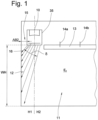
- Fig. 1 first illustrates the position of a lamp according to the invention, designated in its entirety by 10. This is intended for illuminating a building surface 12 of a building room 11.
- the building space 11 has a suspended ceiling 13, which is fixed by means of mounting elements 14a, 14b that are only indicated schematically.
- the suspended ceiling 13 is also referred to as a false ceiling, plasterboard ceiling, ceiling construction or the like.
- the building surface 12 to be illuminated is a vertical building wall. This can have a very large height WH of, for example, up to 10 meters.
- the luminaire 10 according to the invention is arranged in this cove.
- the distance AB2 between the luminaire 10 and the building surface 12 can be only a few centimeters, for example only 10 cm.
- FIG. 2 an embodiment of the lamp according to the invention is shown in a bottom view. It can be seen that the lamp 10 has a width B and a length L. The lamp is therefore elongated in the longitudinal direction R.
- the embodiment of the luminaire 10 according to Fig. 2 has a light exit opening 28 which is essentially rectangular and has approximately the dimensions width B x length L.
- luminaires 10 can be arranged next to one another in the longitudinal direction R, in particular also abutting one another, in order to form a luminaire construction with a total length which corresponds to the total length or a large part of the total length of the building area 12 to be illuminated.
- the cove 15 also preferably extends along the entire length or along a large part of the length of the wall 12.
- the first type of luminaire according to the invention according to the Figures 2 to 8 has a plurality of LEDs 18 (e.g. 18a, 18b, 18c), which are referred to as primary optics, a plurality of collimator optics 17, which are referred to as secondary optics, and a tertiary optic 16 in the form of a plate-shaped element.
- LEDs 18 e.g. 18a, 18b, 18c
- secondary optics e.g. 18a, 18b, 18c
- tertiary optic 16 in the form of a plate-shaped element.
- a first collimator optics 17a, a second collimator optics 17b, and a third collimator optics 17c are shown.
- an LED 18a, an LED 18b, and an LED 18c are shown in the center of the collimator optics 17 in the center of the collimator optics 17 there is an LED 18a, an LED 18b, and an LED 18c.
- the LED 18a can be a single LED or a group of LEDs.
- the collimator optics 17 are essentially rotationally symmetrical and, as best seen from the Figures 3 and 4 As can be seen, it has a cavity 29 which provides a receptacle for the LEDs.
- the light emitted by the LEDs 18 is strongly bundled with the aid of total reflection surfaces and leaves the collimator optics 17 through the light exit surface 25 of the collimator optics 17.
- a light entry surface 23 of the tertiary optics 16 is located at a distance Z from the light exit surface 25 of the collimator optics 17.
- the tertiary optics 16 is designed as a substantially plate-shaped, rectangular element. It is arranged in the light exit opening 28 of the lamp 10.
- the tertiary optics 16, or its light exit surface 24 provides the light exit opening 28 of the luminaire 10.
- the LEDs 18a, 18b, 18c are each arranged at a distance A from each other.
- the distance A provides a grid dimension.
- the external dimensions of the collimator optics 17a, 17b, 17c are in Fig. 2 shown in dashed lines. It can be seen that two collimator optics (e.g. 17a and 17b) are spaced apart from each other. There is a free space 30 between each two collimator optics.
- the luminaire produces 10 different light distributions along the two mutually perpendicular planes E1 and E2.
- Level E1 is defined as the Fig. 2 designated plane E1, which contains the longitudinal direction R of the luminaire 10, and in particular the longitudinal central axis MA of the luminaire 10. It is a plane E1 which is arranged essentially parallel to the building surface 12 to be illuminated. The plane E1 corresponds to the paper plane of the Fig. 4 .
- the plane E2 perpendicular to this, or second plane E2 is the plane E2 which corresponds to the paper plane of the Fig. 3
- the normal vector of this plane E2 is provided by the longitudinal direction R, or by the longitudinal central axis MA.
- the widening means 19 are to be assessed based on the Fig. 4 explained:
- a plurality of lenticular lenses 20 are arranged on the light entry surface 23 of the tertiary optics 16. These extend along the entire width B of the tertiary optics 16 transversely to the paper plane of the Fig. 4
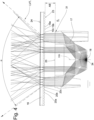
- the parallel or essentially parallel light beam 31 emitted by the collimator optics 17, which is shown by the Fig. 4 represents a very narrow light distribution along the plane E1, strikes the widening means 19, 20, 20a, 20b, 20c and is thereby widened. This results in light emission along the plane E1 at an angle ⁇ of approximately 80°.
- the parallel light beam 31, which hits the light entry surface 23 of the tertiary optics 16 along the plane E2 is not influenced by the light entry surface 23.
- an influence only takes place on the outside, or boundary surface, of the tertiary optics 16.
- a large number of prisms 22 are provided, which are arranged in Fig. 8 are shown slightly enlarged.
- the schematically illustrated light beam 32 which originates from the collimator optics 17 and passes the light entry surface 23 of the tertiary optics 16 without refraction, is deflected by an angle ⁇ when it hits the prism 22a. This results in a light beam 33.
- plane E1 is understood in particular to be the plane which runs as a longitudinal median plane through the luminaire 10 and which contains the longitudinal direction R or the longitudinal median axis MA.
- the plane E1 defines two half-spaces, namely a first half-space H1 and a second half-space H2.
- the first half-space H1 is the Fig. 7 only schematically indicated building area 12.
- the half-space H2 faces away from this building area 12.
- prisms 22 By arranging prisms 22 taking into account individual angles of attack ⁇ and different heights PH of a prism 22b (cf. Fig. 8 ), as well as due to its axial extension (ie the extension transverse to the plane of the paper of the Fig. 8 ) and the positioning on the light exit surface 24 of the tertiary optics 16, a corresponding light deflection and homogenization can take place.
- a light distribution can be achieved on the building surface 12, which illuminates the building surface 12 along the entire building surface height WH and homogeneously illuminated along the entire length of the building surface 12.
- a very narrow light distribution can be achieved at a beam angle ⁇ of less than 10°, which is directed exclusively into a half-space H1.
- a very broad or at least significantly broader light distribution can be achieved along the plane E1, whereby the transitions between individual, spaced-apart collimator optics or spaced-apart LEDs or groups of LEDs are homogenized.
- the lamp housing can be kept very compact and, for example, as in Fig. 1 As indicated, it should be essentially box-shaped.
- the LEDs are mounted on a Fig. 4 only schematically indicated circuit board 34, which is fixedly arranged relative to a bottom of the housing 35.
- the housing of the lamp 10 is in Fig. 1 marked 35.
- the majority of the luminous flux emitted by the luminaire 10 can be directed into the half-space H1 and thus efficiently used to illuminate the wall surface 12.
- the invention also covers luminaire types in which only a small proportion of the luminous flux is directed into the half-space H1.
- the predominant portion of the total luminous flux i.e. in particular more than 55%, preferably more than 60%, further preferably more than 70% of the total luminous flux, is to be guided or directed into the half-space H1 in order to be able to be used there to illuminate the building surface 12.
- collimator optics 17a, 17b, 17c can be overlapped by a plate-shaped tertiary optic 16. This enables a particularly advantageous optical design of the luminaire.
- the tertiary optics 16 can be designed to be continuous in this way, which enables a correspondingly uniform overall impression of the luminaire.
- the individual prisms 22a, 22b, 22c, etc. extend over the entire axial length of the tertiary optics 16. In other embodiments, the axial length of the individual prisms 22 can also be shorter.
- the scattered light beam designated 38 is intended to make it clear that sections of the building surface 12 arranged immediately adjacent to the luminaire 10 can also be illuminated with scattered light.
- edge beams are preferably used which leave the collimator optics 17 in the area 39 of its outer edge.
- a translucent window element 40 as shown in Figure 5 visible, arranged.
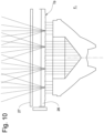
- the tertiary optics 16 are provided by a first plate 26 and a second plate 27. These can also be spaced apart from each other by a distance U.
- the first plate 26 provides widening means 19 on its light entry side
- the second plate 27 provides light deflection means 21 on its exit side.
- These can be designed identically to the widening means and light deflection means of the first embodiment.
- the output side 36 of the first plate 26 and the input side 37 of the second plate 27 are essentially smooth and thus have no lighting function.
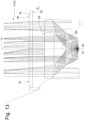
- the third embodiment according to the Figures 11 to 13 is characterized in that there is no free space between two adjacent collimator optics 17a and 17b, but the two collimator optics are located directly opposite each other.
- widening means 19 on the tertiary optics 16, as is Fig. 12 This is where a homogeneous, even illumination of the building surface along the entire longitudinal direction R the luminaire 10, or along the longitudinal direction of the entire building surface 12, without the need for widening means.
- light deflection can also be achieved here with the aid of the light deflection means 21 (cf. Figure 13 ) in only one of the two half-spaces, namely in the half-space H1 which is adjacent to the building area 12 to be illuminated.
Landscapes
- Physics & Mathematics (AREA)
- General Physics & Mathematics (AREA)
- Optics & Photonics (AREA)
- Engineering & Computer Science (AREA)
- General Engineering & Computer Science (AREA)
- Non-Portable Lighting Devices Or Systems Thereof (AREA)
Applications Claiming Priority (2)
| Application Number | Priority Date | Filing Date | Title |
|---|---|---|---|
| DE102013021053.4A DE102013021053B4 (de) | 2013-12-18 | 2013-12-18 | Leuchte |
| EP14004190.6A EP2887115B1 (fr) | 2013-12-18 | 2014-12-12 | Éclairage |
Related Parent Applications (2)
| Application Number | Title | Priority Date | Filing Date |
|---|---|---|---|
| EP14004190.6A Division-Into EP2887115B1 (fr) | 2013-12-18 | 2014-12-12 | Éclairage |
| EP14004190.6A Division EP2887115B1 (fr) | 2013-12-18 | 2014-12-12 | Éclairage |
Publications (2)
| Publication Number | Publication Date |
|---|---|
| EP4451019A2 true EP4451019A2 (fr) | 2024-10-23 |
| EP4451019A3 EP4451019A3 (fr) | 2025-01-01 |
Family
ID=52144339
Family Applications (2)
| Application Number | Title | Priority Date | Filing Date |
|---|---|---|---|
| EP24192159.2A Pending EP4451019A3 (fr) | 2013-12-18 | 2014-12-12 | Luminaire |
| EP14004190.6A Active EP2887115B1 (fr) | 2013-12-18 | 2014-12-12 | Éclairage |
Family Applications After (1)
| Application Number | Title | Priority Date | Filing Date |
|---|---|---|---|
| EP14004190.6A Active EP2887115B1 (fr) | 2013-12-18 | 2014-12-12 | Éclairage |
Country Status (4)
| Country | Link |
|---|---|
| EP (2) | EP4451019A3 (fr) |
| CN (1) | CN104728771A (fr) |
| DE (1) | DE102013021053B4 (fr) |
| ES (1) | ES2996032T3 (fr) |
Families Citing this family (5)
| Publication number | Priority date | Publication date | Assignee | Title |
|---|---|---|---|---|
| EP3324103B1 (fr) | 2016-11-22 | 2021-06-16 | odelo GmbH | Phare de véhicule avec fonction d'éclairage à action en profondeur |
| DE102017125230A1 (de) * | 2017-10-27 | 2019-05-02 | Siteco Beleuchtungstechnik Gmbh | Linse, linsenanordnung und leuchtmodul |
| DE102019119682A1 (de) | 2019-07-19 | 2021-01-21 | Erco Gmbh | Gebäudeleuchte |
| EP4411211A1 (fr) * | 2023-02-02 | 2024-08-07 | Steris | Dispositif d'eclairage |
| FI131762B1 (en) * | 2023-09-26 | 2025-11-17 | Ledil Oy | Optical system for modifying light distribution |
Citations (1)
| Publication number | Priority date | Publication date | Assignee | Title |
|---|---|---|---|---|
| DE102009053422A1 (de) | 2009-11-19 | 2011-06-01 | Erco Gmbh | Linsenelement für eine Lichtquelle u. a. |
Family Cites Families (9)
| Publication number | Priority date | Publication date | Assignee | Title |
|---|---|---|---|---|
| US5949933A (en) * | 1998-03-03 | 1999-09-07 | Alliedsignal Inc. | Lenticular illumination system |
| JP4863357B2 (ja) * | 2006-01-24 | 2012-01-25 | 株式会社エンプラス | 発光装置、面光源装置、表示装置及び光束制御部材 |
| DE202007013205U1 (de) | 2007-07-26 | 2008-12-11 | Erco Leuchten Gmbh | Leuchte |
| WO2009078439A1 (fr) * | 2007-12-18 | 2009-06-25 | Takiron Co., Ltd. | Pellicule optique et unité de rétroéclairage qui utilise celle-ci |
| DE202007017946U1 (de) | 2007-12-20 | 2009-04-23 | Erco Gmbh | Prismenscheibe und Leuchte |
| WO2010010494A1 (fr) | 2008-07-24 | 2010-01-28 | Koninklijke Philips Electronics N.V. | Luminaire doté de plusieurs unités d’éclairage |
| DE102008063369B4 (de) * | 2008-12-30 | 2016-12-15 | Erco Gmbh | Leuchte und Modulsystem für Leuchten |
| DE102009060566A1 (de) | 2009-12-23 | 2011-06-30 | ERCO GmbH, 58507 | Leuchte |
| DE102010008359A1 (de) * | 2010-02-17 | 2011-08-18 | ERCO GmbH, 58507 | Beleuchtungsanordnung |
-
2013
- 2013-12-18 DE DE102013021053.4A patent/DE102013021053B4/de active Active
-
2014
- 2014-12-12 EP EP24192159.2A patent/EP4451019A3/fr active Pending
- 2014-12-12 EP EP14004190.6A patent/EP2887115B1/fr active Active
- 2014-12-12 ES ES14004190T patent/ES2996032T3/es active Active
- 2014-12-18 CN CN201410858328.7A patent/CN104728771A/zh active Pending
Patent Citations (1)
| Publication number | Priority date | Publication date | Assignee | Title |
|---|---|---|---|---|
| DE102009053422A1 (de) | 2009-11-19 | 2011-06-01 | Erco Gmbh | Linsenelement für eine Lichtquelle u. a. |
Also Published As
| Publication number | Publication date |
|---|---|
| EP2887115A1 (fr) | 2015-06-24 |
| DE102013021053A1 (de) | 2015-06-18 |
| CN104728771A (zh) | 2015-06-24 |
| DE102013021053B4 (de) | 2018-03-01 |
| EP2887115B1 (fr) | 2024-10-09 |
| ES2996032T3 (en) | 2025-02-12 |
| EP4451019A3 (fr) | 2025-01-01 |
Similar Documents
| Publication | Publication Date | Title |
|---|---|---|
| EP3494343B1 (fr) | Phare de véhicule | |
| EP2378187B1 (fr) | Dispositif de guidage de lumière modulaire pour dispositifs d'éclairage de véhicule automobile | |
| EP2893249B1 (fr) | Unité d'éclairage destinée à un projecteur | |
| AT520400B1 (de) | Beleuchtungs- und/oder signalisierungsvorrichtung für ein kraftfahrzeug | |
| DE102013011877B4 (de) | Leuchte mit einer Kollimatoroptik | |
| EP3134675B1 (fr) | Element optique pour une del, systeme de del avec un tel element optique et lampe avec un tel systeme de del | |
| EP2887115B1 (fr) | Éclairage | |
| DE102013226181A1 (de) | Optisches Element, sowie Anordnung zur Lichtabgabe | |
| DE102011078287A1 (de) | Lichtlenkungselement | |
| DE202012000567U1 (de) | Beleuchtungseinrichtung für ein Kraftfahrzeug | |
| EP3071879A1 (fr) | Élément optique et dispositif d'éclairage doté d'un élément optique | |
| EP3607247B1 (fr) | Lampe | |
| DE102014206593A1 (de) | Kraftfahrzeugleuchte mit Wischeffekt | |
| AT16666U1 (de) | Beleuchtungsanordnung | |
| DE102013021308B4 (de) | Leuchte | |
| AT520398B1 (de) | Beleuchtungs- und/oder signalisierungsvorrichtung für ein kraftfahrzeug | |
| EP3283820A1 (fr) | Système optique et ensemble d'émission de lumière | |
| EP3341648B1 (fr) | Élément optique | |
| DE202013101038U1 (de) | Fahrzeuginnenleuchte | |
| AT16042U1 (de) | Optisches Element sowie Anordnung zur Lichtabgabe mit einem optischen Element | |
| DE102014104336A1 (de) | LED-Leuchte mit refraktiver Optik zur Lichtdurchmischung | |
| EP3767159B1 (fr) | Éclairage de secours | |
| EP3550205A1 (fr) | Conducteur de lumière pour un module lumineux de véhicule automobile | |
| EP1843082B1 (fr) | Plafonnier, en particulier pour utilisation dans un couloir | |
| EP2615367A1 (fr) | Eclairage |
Legal Events
| Date | Code | Title | Description |
|---|---|---|---|
| PUAI | Public reference made under article 153(3) epc to a published international application that has entered the european phase |
Free format text: ORIGINAL CODE: 0009012 |
|
| STAA | Information on the status of an ep patent application or granted ep patent |
Free format text: STATUS: THE APPLICATION HAS BEEN PUBLISHED |
|
| AC | Divisional application: reference to earlier application |
Ref document number: 2887115 Country of ref document: EP Kind code of ref document: P |
|
| AK | Designated contracting states |
Kind code of ref document: A2 Designated state(s): AL AT BE BG CH CY CZ DE DK EE ES FI FR GB GR HR HU IE IS IT LI LT LU LV MC MK MT NL NO PL PT RO RS SE SI SK SM TR |
|
| REG | Reference to a national code |
Ref country code: DE Ref legal event code: R079 Free format text: PREVIOUS MAIN CLASS: G02B0005040000 Ipc: G02B0019000000 |
|
| PUAL | Search report despatched |
Free format text: ORIGINAL CODE: 0009013 |
|
| AK | Designated contracting states |
Kind code of ref document: A3 Designated state(s): AL AT BE BG CH CY CZ DE DK EE ES FI FR GB GR HR HU IE IS IT LI LT LU LV MC MK MT NL NO PL PT RO RS SE SI SK SM TR |
|
| RIC1 | Information provided on ipc code assigned before grant |
Ipc: G02B 5/04 20060101ALI20241127BHEP Ipc: G02B 3/00 20060101ALI20241127BHEP Ipc: G02B 19/00 20060101AFI20241127BHEP |
|
| STAA | Information on the status of an ep patent application or granted ep patent |
Free format text: STATUS: REQUEST FOR EXAMINATION WAS MADE |
|
| 17P | Request for examination filed |
Effective date: 20250604 |