EP4451034A1 - Lampe médicale - Google Patents
Lampe médicale Download PDFInfo
- Publication number
- EP4451034A1 EP4451034A1 EP24170117.6A EP24170117A EP4451034A1 EP 4451034 A1 EP4451034 A1 EP 4451034A1 EP 24170117 A EP24170117 A EP 24170117A EP 4451034 A1 EP4451034 A1 EP 4451034A1
- Authority
- EP
- European Patent Office
- Prior art keywords
- lens
- light source
- luminaire according
- condenser
- housing
- Prior art date
- Legal status (The legal status is an assumption and is not a legal conclusion. Google has not performed a legal analysis and makes no representation as to the accuracy of the status listed.)
- Pending
Links
Images


Classifications
-
- G—PHYSICS
- G02—OPTICS
- G02B—OPTICAL ELEMENTS, SYSTEMS OR APPARATUS
- G02B19/00—Condensers, e.g. light collectors or similar non-imaging optics
- G02B19/0004—Condensers, e.g. light collectors or similar non-imaging optics characterised by the optical means employed
- G02B19/0009—Condensers, e.g. light collectors or similar non-imaging optics characterised by the optical means employed having refractive surfaces only
- G02B19/0014—Condensers, e.g. light collectors or similar non-imaging optics characterised by the optical means employed having refractive surfaces only at least one surface having optical power
-
- A—HUMAN NECESSITIES
- A61—MEDICAL OR VETERINARY SCIENCE; HYGIENE
- A61B—DIAGNOSIS; SURGERY; IDENTIFICATION
- A61B90/00—Instruments, implements or accessories specially adapted for surgery or diagnosis and not covered by any of the groups A61B1/00 - A61B50/00, e.g. for luxation treatment or for protecting wound edges
- A61B90/30—Devices for illuminating a surgical field, the devices having an interrelation with other surgical devices or with a surgical procedure
-
- F—MECHANICAL ENGINEERING; LIGHTING; HEATING; WEAPONS; BLASTING
- F21—LIGHTING
- F21V—FUNCTIONAL FEATURES OR DETAILS OF LIGHTING DEVICES OR SYSTEMS THEREOF; STRUCTURAL COMBINATIONS OF LIGHTING DEVICES WITH OTHER ARTICLES, NOT OTHERWISE PROVIDED FOR
- F21V21/00—Supporting, suspending, or attaching arrangements for lighting devices; Hand grips
- F21V21/08—Devices for easy attachment to any desired place, e.g. clip, clamp, magnet
- F21V21/084—Head fittings
-
- F—MECHANICAL ENGINEERING; LIGHTING; HEATING; WEAPONS; BLASTING
- F21—LIGHTING
- F21V—FUNCTIONAL FEATURES OR DETAILS OF LIGHTING DEVICES OR SYSTEMS THEREOF; STRUCTURAL COMBINATIONS OF LIGHTING DEVICES WITH OTHER ARTICLES, NOT OTHERWISE PROVIDED FOR
- F21V5/00—Refractors for light sources
- F21V5/008—Combination of two or more successive refractors along an optical axis
-
- F—MECHANICAL ENGINEERING; LIGHTING; HEATING; WEAPONS; BLASTING
- F21—LIGHTING
- F21V—FUNCTIONAL FEATURES OR DETAILS OF LIGHTING DEVICES OR SYSTEMS THEREOF; STRUCTURAL COMBINATIONS OF LIGHTING DEVICES WITH OTHER ARTICLES, NOT OTHERWISE PROVIDED FOR
- F21V5/00—Refractors for light sources
- F21V5/04—Refractors for light sources of lens shape
-
- G—PHYSICS
- G02—OPTICS
- G02B—OPTICAL ELEMENTS, SYSTEMS OR APPARATUS
- G02B19/00—Condensers, e.g. light collectors or similar non-imaging optics
- G02B19/0033—Condensers, e.g. light collectors or similar non-imaging optics characterised by the use
- G02B19/0047—Condensers, e.g. light collectors or similar non-imaging optics characterised by the use for use with a light source
- G02B19/0061—Condensers, e.g. light collectors or similar non-imaging optics characterised by the use for use with a light source the light source comprising a LED
-
- A—HUMAN NECESSITIES
- A61—MEDICAL OR VETERINARY SCIENCE; HYGIENE
- A61B—DIAGNOSIS; SURGERY; IDENTIFICATION
- A61B90/00—Instruments, implements or accessories specially adapted for surgery or diagnosis and not covered by any of the groups A61B1/00 - A61B50/00, e.g. for luxation treatment or for protecting wound edges
- A61B90/30—Devices for illuminating a surgical field, the devices having an interrelation with other surgical devices or with a surgical procedure
- A61B2090/309—Devices for illuminating a surgical field, the devices having an interrelation with other surgical devices or with a surgical procedure using white LEDs
-
- A—HUMAN NECESSITIES
- A61—MEDICAL OR VETERINARY SCIENCE; HYGIENE
- A61B—DIAGNOSIS; SURGERY; IDENTIFICATION
- A61B90/00—Instruments, implements or accessories specially adapted for surgery or diagnosis and not covered by any of the groups A61B1/00 - A61B50/00, e.g. for luxation treatment or for protecting wound edges
- A61B90/50—Supports for surgical instruments, e.g. articulated arms
- A61B2090/502—Headgear, e.g. helmet, spectacles
-
- F—MECHANICAL ENGINEERING; LIGHTING; HEATING; WEAPONS; BLASTING
- F21—LIGHTING
- F21W—INDEXING SCHEME ASSOCIATED WITH SUBCLASSES F21K, F21L, F21S and F21V, RELATING TO USES OR APPLICATIONS OF LIGHTING DEVICES OR SYSTEMS
- F21W2131/00—Use or application of lighting devices or systems not provided for in codes F21W2102/00-F21W2121/00
- F21W2131/20—Lighting for medical use
-
- F—MECHANICAL ENGINEERING; LIGHTING; HEATING; WEAPONS; BLASTING
- F21—LIGHTING
- F21W—INDEXING SCHEME ASSOCIATED WITH SUBCLASSES F21K, F21L, F21S and F21V, RELATING TO USES OR APPLICATIONS OF LIGHTING DEVICES OR SYSTEMS
- F21W2131/00—Use or application of lighting devices or systems not provided for in codes F21W2102/00-F21W2121/00
- F21W2131/20—Lighting for medical use
- F21W2131/205—Lighting for medical use for operating theatres
-
- F—MECHANICAL ENGINEERING; LIGHTING; HEATING; WEAPONS; BLASTING
- F21—LIGHTING
- F21Y—INDEXING SCHEME ASSOCIATED WITH SUBCLASSES F21K, F21L, F21S and F21V, RELATING TO THE FORM OR THE KIND OF THE LIGHT SOURCES OR OF THE COLOUR OF THE LIGHT EMITTED
- F21Y2115/00—Light-generating elements of semiconductor light sources
- F21Y2115/10—Light-emitting diodes [LED]
Definitions
- the invention relates to a medical lamp for generating a light field.
- Medical lights are well known and are used to create a light field in order to optimally illuminate an examination, treatment or surgical area.
- Optimal illumination means that the light field has a high light intensity and at the same time has a homogeneous illuminance distribution so that no differences in brightness occur within the examination, treatment or operation field that would make an examination, treatment or operation more difficult.
- medical lights should be as compact as possible so that they are mobile.
- medical lights should be able to be worn comfortably on the head for a longer period of time, for example during an operation, using a headband.
- a medical lamp for generating a light field in a light field plane, with a housing and a light source and an optics arranged in the housing.
- the optics have a condenser and an objective part, the condenser being arranged adjacent to the light source and having two lenses that generate an intermediate image of the far field of the light source.
- the objective part projects the intermediate image of the far field into the light field plane.
- the lens part that images the intermediate image already receives an intermediate image with a homogeneous illuminance distribution.
- the light field generated by the lens part also has an extremely homogeneous illuminance distribution.
- the structure of the condenser with two lenses enables an extremely compact shape.
- the condenser is immediately adjacent to the light source, i.e. without any further optical components between the condenser and the light source.
- the optics is an imaging optics and/or the imaging for generating the intermediate image is an aplanatic imaging, so that the quality of the intermediate image can be further improved.
- the condenser allows the light source, which is assumed to be telecentric, to be imaged towards infinity, which makes the illuminance distribution particularly uniform.
- the intermediate image can be located inside the housing.
- the intermediate image has a distance from the light source of less than 15 mm, in particular less than 8 mm, and/or a distance from the last of the lenses of the condenser of less than 4 mm, in particular less than 3 mm, thereby achieving a particularly compact luminaire.
- the condenser has a center thickness of less than 15 mm, in particular less than 5 mm in the direction of the optical axis.
- the condenser has a numerical aperture of at least 0.80, in particular at least or equal to 0.85, whereby the brightness of the illuminated field is further increased.
- the at least one of the lenses of the condenser in particular the first lens of the condenser, can have at least one surface that has an aspherical shape, in particular wherein both surfaces of the respective lens have an aspherical shape.
- surface refers to both the entrance and exit surfaces of a lens.
- the condenser has an aspherical convex lens and a spherical convex lens.
- the light field plane has a fixed distance from the light source, in particular more than 20 cm and/or less than 70 cm, for example between 30 cm and 40 cm.
- the light is used as When a head lamp is used, the light field is created at a distance that is comfortable for the wearer and his eyes.
- the light field is therefore outside the housing and outside the lamp itself.
- the optics can be free of a mechanical aperture, in particular a pinhole or an iris diaphragm.
- the lens part consists of one or two lenses fixed in the housing and/or has a fixed focal length, thereby reducing the complexity of the lens part.
- the objective part is a pancratic system with at least one movable lens group, which is arranged in the housing in such a way that it can be moved along the optical axis between two end positions.
- the size of the light field can be adjusted without changing the numerical aperture and therefore without changing the luminous flux.
- this embodiment according to the invention has the advantage that the illuminance is many times higher, at least for small light field sizes.
- a lens group within the meaning of this disclosure may consist of one, two or more than two lenses.
- the lens groups can be moved within the housing.
- the lens part is designed in such a way that it covers the intermediate image of the far field to at least 90%, in particular completely, for different positions of the at least one displaceable lens group. into the luminous field plane, in particular for the end positions of the at least one lens group, whereby a continuous adjustment of the luminous field is achieved without loss of quality.
- one of the lens groups can be moved into the intermediate image.
- the intermediate image is imaged, since it is present in other positions of the lens group.
- two movable lens groups are provided to reduce the size.
- the light has a holder that holds the housing, in particular wherein the holder has a headband for wearing on a human head, a wall mount, a table mount, a tripod, in particular a rolling tripod, and/or a stand.
- the light can be securely attached to various objects.
- the bracket allows movement of the housing relative to the rest of the bracket, in particular by means of a flexible arm.
- the holder is free of optical components.
- the light source comprises one or more LEDs, in particular wherein the light source consists of exactly one LED, thereby further reducing the size.
- the one or more LEDs are free of a lens and/or free of bonding wires, and/or the one or more LEDs are CSP LEDs (chip-scale package LEDs) or flip-chip LEDs. Such LEDs are used to create light sources with very high luminances in a small size.
- Figure 1 shows a medical lamp 10 with a holder 12 and a housing 14.
- the lamp 10 of the first embodiment is designed as a head lamp.
- the holder 12 accordingly has a headband 16 for wearing on the head and an arm 18 which extends from the headband and holds the housing 14.
- the arm 18 can be flexible and/or have joints.
- the arm 18 makes it possible to move the housing 14 relative to the rest of the holder, in particular the headband 16.
- the holder 12 is free of optical components.
- the lamp 10 also has a power supply, for example a battery or an accumulator, which is Figure 1 is not shown.
- a power supply for example a battery or an accumulator, which is Figure 1 is not shown.
- Figure 2 shows a very schematic cross-section through the housing 14.
- An optics 20 of the lamp 10 and a light source 22 of the lamp 10 are arranged within the housing 14.
- the housing 14 has a cylindrical interior, in particular a circular cylindrical interior, in which the optics 20 and light source 22 are arranged.
- the housing 14 has a wall on a first end face, while the opposite, second end face is open.
- the housing 14 has a length from end to end between 40 mm and 100 mm.
- the second front side of the housing 14 is closed by a cover glass 24, so that the interior of the housing 14 is closed, with openings for a power supply.
- the cover glass 24 is, for example, a plane-parallel disk that has no or only a very slight influence on the beam path of the optics 20 and is not considered part of the optics 20.
- the cover glass 24 prevents dirt or liquid from penetrating the housing 14 and contaminating the optics 20.
- the light source 22 is provided on the first end face of the housing 14 and the optics 20 are arranged between the light source 22 and the cover glass 24.
- the cover glass 24 is therefore arranged on the side of the optics 20 facing away from the light source 22.
- the light source 22 is assumed to be a telecentric radiator. In the embodiment shown, it consists of exactly one LED. However, it is also conceivable that the light source 22 comprises one or more LEDs.
- the LED for example, has a size of 1.2 mm x 1.2 mm.
- the LED is free of a lens and/or free of bonding wires.
- the LED is designed as a flip-chip LED. It is also conceivable that a CSP LED (chip-scale package LED) is used as the light source 22.
- the optics 20 is an imaging optics and serves to generate a light field F in a light field plane E from the light emitted by the light source 22.
- the light field plane E has a fixed distance A L from the light source 22, ie from the edge of the light source 22 facing the light field F, and a fixed distance Ao from the optics 20, more precisely the last lens of the objective part.
- the distances A L and Ao are greater than 20 cm and/or less than 70 cm and are, for example, between 30 cm and 40 cm.
- the illuminated field F is therefore outside the housing 14.
- the optics 20 have a condenser 26 and an objective part 28.
- the optics 20 consists of the condenser 26 and the objective part 28.
- the optics 20 has an optical axis O which corresponds to the axial direction of the housing 14.
- Figure 1 the beam path of the light rays of the light source 22 is shown, which extend from the part of the light source 22 which is located above the optical axis O.
- the figures show the beam path through the condenser 26 and the objective part 28.
- the objective part 28 has only one lens, namely an objective lens 30, which is fixed in the housing 14.
- the objective lens 30 cannot be moved along the optical axis O within the housing 14.
- the objective lens 30 is also the last lens of the objective part 28.
- the objective lens 30 and/or other lenses of the objective part 28 can be designed as achromatic lenses in order to reduce color errors at the edge of the illuminated field.
- the condenser 26 is arranged between the light source 22 and the lens part 28.
- the condenser 26 is provided adjacent to the light source 22, in particular immediately adjacent without further optical components between the condenser 26 and the light source 22.
- the condenser 26 In the direction of the optical axis O, the condenser 26 has a center thickness of less than 15 mm, in particular less than 5 mm.
- the condenser 26 has exactly two lenses, namely a first lens 32 and a last lens 34, which represents the second lens in the embodiment shown.
- the condenser 26 has more than two lenses 32, 34.
- the condenser 26, and thus the first lens 32 and the last lens 34, is firmly fixed in the housing 14 and cannot move along the optical axis O.
- the condenser 26 has a numerical aperture of at least 0.8, in particular of at least or equal to 0.85.
- the first lens 32 faces the light source 22 and the last lens 34 faces the objective part 28.
- the surfaces of the first lens 32 both have an aspherical shape, which differ from each other.
- the surfaces of the last lens 34 each have an aspherical shape.
- the condenser 26 has an aspherical convex lens and a spherical convex lens as lenses 32 and 34, respectively.
- the first lens 32 and the second lens 34 are designed and arranged such that they, i.e. the condenser 26, produce an intermediate image Z of the far field of the light source 22.
- the intermediate image Z of the far field of the light source 22 can also be viewed as an image of the angular distribution of the light source 22.
- the intermediate image Z is not an image of the light source 22 and its structure.
- the light source 22 is imaged towards infinity.
- the intermediate image Z also has a sharp edge perpendicular to the optical axis O, i.e. the light intensity at the edge decreases almost step-like.
- a “sharp edge” is understood to mean that the edge region of the luminous field in which the intensity of the luminous field decreases from a first intensity to a second intensity is smaller than 10% of the radius of the luminous field and/or smaller than 2 mm (measured in the luminous field plane), in particular wherein the first intensity is between 80% and 95% of the maximum intensity of the luminous field and/or the second intensity is between 10% and 20% of the maximum intensity of the luminous field.
- the radius of the light field corresponds to the greatest distance of the points at which the light field has the second intensity from the geometric center of the light field.
- a “sharp edge” means that there are no color fringes at the edge of the light field. Color fringes can be seen as areas of the light field in which the intensity of individual wavelength ranges of visible light has dropped so sharply compared to other wavelength ranges of visible light that this area of the light field is colored.
- a mechanical aperture such as a pinhole or an iris diaphragm, which creates a sharp edge of the light field, is not present.
- the condenser 26 and the entire optics 20 are therefore free of a mechanical aperture.
- the lenses 32, 34 also produce an aplanatic image of the light source.
- the image for producing the intermediate image Z thus satisfies one of the aplanatic conditions.
- the intermediate image Z has a distance from the light source 22 of less than 15 mm, in particular less than 8 mm.
- the distance between the last lens 34 of the condenser 26 and the intermediate image Z is less than 4 mm, in particular less than 3 mm.
- the intermediate image Z is thus located within the housing 14.
- the generated intermediate image Z is, as in Figure 2 can be seen, is imaged by the objective part 28, in the first embodiment thus by the lens 30, into the luminous field plane E.
- the image of the intermediate image Z in the luminous field plane E is the luminous field F.
- the light field F has a sharp edge in the light field plane E, since the intermediate image Z already has a sharp edge. At the same time, the light field F is extremely homogeneously illuminated, since the intermediate image Z has an extremely homogeneous illuminance distribution.
- the quality of the luminous field F in particular the homogeneity of the illuminance distribution and the definition of the edge of the luminous field F, are therefore largely dependent on the quality of the intermediate image Z.
- the high quality of the intermediate image Z is due to the condenser 26, so that a high-quality light field F with high intensity and homogeneous illuminance distribution is made possible by the condenser 26. At the same time, an extremely compact design is achieved.
- the high-quality intermediate image Z is thus generated.
- Figure 4 is another embodiment of the medical lamp 10 in a view corresponding to the Figure 2 shown.
- the medical lamp 10 of the second embodiment has a different lens part 28.
- the lens part 28 of the second embodiment has two lenses, namely a first objective lens 36 and the objective lens 30 as a second lens.
- the first objective lens 30 is arranged adjacent to the condenser 26 and the objective lens 30 is provided adjacent to the cover glass 24.
- the lenses 30, 36 of the lens part 28 are fixed in the housing 14 as already discussed for the first embodiment, so that the lens part 28 of the second embodiment also has a fixed focal length.
- the diameter of the light field F in the light field plane E is larger.
- FIG. 5 and 6 is a third embodiment of the medical lamp 10 in schematic representations corresponding to that of Figure 2 shown.
- a different lens part 28 is used.
- the objective part 28 in the third embodiment is a pancratic system with two lens groups, namely a first lens group 38 and a second lens group 40.
- the lens groups 38, 40 can have or consist of one, two or more lenses.
- the first lens group 38 consists of a single lens and the second lens group 40 consists of two lenses.
- the lens groups 38, 40 are mounted in the housing 14 so that they can move along the optical axis.
- the lens groups 38, 40 can be moved via a common mechanism which is designed such that the lens groups 38, 40 can be moved between two end positions.
- the Figures 5 and 6 show the position of the lens groups 38, 40 in one of the two end positions.
- the lens groups 38, 40 When moving between the end positions, the lens groups 38, 40 are predominantly moved in opposite directions to each other, as shown by the arrows in Figure 5 indicated.
- the lens part 28 forms the intermediate image Z in the luminous field plane E, i.e. at least 90%, but in particular completely. This applies in particular to the end positions, but also to every position of the lens groups 38, 40 between the end positions.
- the first lens group 38 is placed so close to the condenser 26 that the intermediate image Z would be created within the first lens group 38 or behind it.
- the intermediate image is imaged, since it is present when the lens groups 38, 40 are in other positions.
- the Intermediate image Z is present for the majority of the possible positions between the two end positions of the lens groups 38, 40.
- the lens part 28 of the third embodiment acts similarly to a zoom lens for cameras.
- This embodiment represents a pancratic optical system.
- the size of the light field F in the light field plane E depends on the position of the lens groups 38, 40, whereby the Figure 5 End positions shown the light field F and the in Figure 6 shown end positions produce the largest light field F in the light field plane E.
- the lens part 28 of the third embodiment not only is the focal length adjustable, but the image and object distance also remain the same. This means that the edge of the illuminated field F always remains sharp when the size of the illuminated field is adjusted.
- This image is also a complete optical image, so that due to the conservation of optice, not only the luminous field F is enlarged or reduced, but also the intensity within the luminous field F at the same time. For example, the intensity is increased when the luminous field F is reduced, since at any time almost the entire light power emitted by the light source 22 is imaged into the luminous field F.
- the lamp 10 according to the invention thus provides a compact medical lamp 10 which provides a light field F with variable size and variable intensity.
- the medical Even in the third embodiment, the lamp 10 is so compact that it can be worn on the head by means of the headband 16.
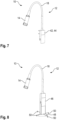
- FIG. 7 a further embodiment of the medical lamp 10 is shown, which differs from the first three embodiments by its holder 12.
- the holder 12 comprises a wall mount 42 or a table mount 44 for fastening the medical lamp 10 to a table top.
- the housing 14 is movable via the arm 18 relative to the wall mount 42 or the table mount 44.
- the holder 12 of the embodiment according to Figure 8 has a tripod 46 or a base 48 (shown in dashed lines).
- the tripod 46 can have several rollers 50, i.e. can be a rolling tripod.
Landscapes
- Physics & Mathematics (AREA)
- Engineering & Computer Science (AREA)
- General Engineering & Computer Science (AREA)
- Health & Medical Sciences (AREA)
- Life Sciences & Earth Sciences (AREA)
- Surgery (AREA)
- Optics & Photonics (AREA)
- General Physics & Mathematics (AREA)
- Biomedical Technology (AREA)
- Pathology (AREA)
- Oral & Maxillofacial Surgery (AREA)
- Nuclear Medicine, Radiotherapy & Molecular Imaging (AREA)
- Heart & Thoracic Surgery (AREA)
- Medical Informatics (AREA)
- Molecular Biology (AREA)
- Animal Behavior & Ethology (AREA)
- General Health & Medical Sciences (AREA)
- Public Health (AREA)
- Veterinary Medicine (AREA)
- Lenses (AREA)
Applications Claiming Priority (1)
| Application Number | Priority Date | Filing Date | Title |
|---|---|---|---|
| DE102023110090.4A DE102023110090A1 (de) | 2023-04-20 | 2023-04-20 | Medizinische Leuchte |
Publications (1)
| Publication Number | Publication Date |
|---|---|
| EP4451034A1 true EP4451034A1 (fr) | 2024-10-23 |
Family
ID=92894421
Family Applications (1)
| Application Number | Title | Priority Date | Filing Date |
|---|---|---|---|
| EP24170117.6A Pending EP4451034A1 (fr) | 2023-04-20 | 2024-04-12 | Lampe médicale |
Country Status (2)
| Country | Link |
|---|---|
| EP (1) | EP4451034A1 (fr) |
| DE (1) | DE102023110090A1 (fr) |
Citations (5)
| Publication number | Priority date | Publication date | Assignee | Title |
|---|---|---|---|---|
| US20060285316A1 (en) * | 2005-06-20 | 2006-12-21 | Welch Allyn, Inc. | Hybrid surgical headlight system utilizing dual illumination paths and coaxial optics |
| US20100309549A1 (en) * | 2009-06-09 | 2010-12-09 | Carl Zeiss Surgical Gmbh | Light source arrangement for an illumination device of a medical-optical observation |
| US20120120635A1 (en) * | 2010-11-17 | 2012-05-17 | James Strong | Wearable headlight devices and related methods |
| WO2013120234A1 (fr) * | 2012-02-16 | 2013-08-22 | 舞阳县龙田精密仪器有限责任公司 | Lampe torche de zoom |
| US20210382261A1 (en) * | 2020-06-04 | 2021-12-09 | Saga Optics Co., Limited | Infrared Zoom Illuminating Device |
Family Cites Families (4)
| Publication number | Priority date | Publication date | Assignee | Title |
|---|---|---|---|---|
| DE1609883U (de) * | 1949-11-14 | 1950-07-13 | Zeiss Opton Optische Werke Obe | Fokussierbare beleuchtungsanordnung, die aus mehreren gekuppelten einzelleuchten besteht. |
| DE2717233A1 (de) * | 1977-04-19 | 1978-11-02 | Strahlen Umweltforsch Gmbh | Lichtquelle |
| DD259023A1 (de) * | 1987-03-23 | 1988-08-10 | Narva Rosa Luxemburg K | Verfolgungsscheinwerfer |
| DE10246889B4 (de) * | 2002-10-08 | 2004-08-19 | Karl Kaps Gmbh & Co. Kg | Beleuchtungseinrichtung für ein optisches Vergrösserungsgerät sowie optisches Vergrösserungsgerät |
-
2023
- 2023-04-20 DE DE102023110090.4A patent/DE102023110090A1/de active Pending
-
2024
- 2024-04-12 EP EP24170117.6A patent/EP4451034A1/fr active Pending
Patent Citations (5)
| Publication number | Priority date | Publication date | Assignee | Title |
|---|---|---|---|---|
| US20060285316A1 (en) * | 2005-06-20 | 2006-12-21 | Welch Allyn, Inc. | Hybrid surgical headlight system utilizing dual illumination paths and coaxial optics |
| US20100309549A1 (en) * | 2009-06-09 | 2010-12-09 | Carl Zeiss Surgical Gmbh | Light source arrangement for an illumination device of a medical-optical observation |
| US20120120635A1 (en) * | 2010-11-17 | 2012-05-17 | James Strong | Wearable headlight devices and related methods |
| WO2013120234A1 (fr) * | 2012-02-16 | 2013-08-22 | 舞阳县龙田精密仪器有限责任公司 | Lampe torche de zoom |
| US20210382261A1 (en) * | 2020-06-04 | 2021-12-09 | Saga Optics Co., Limited | Infrared Zoom Illuminating Device |
Also Published As
| Publication number | Publication date |
|---|---|
| DE102023110090A1 (de) | 2024-10-24 |
Similar Documents
| Publication | Publication Date | Title |
|---|---|---|
| EP0385262B1 (fr) | Appareil d'observation avec système d'illumination réfléchie pour des objets y | |
| DE3442218C2 (fr) | ||
| EP2452616B1 (fr) | Dispositif d'observation | |
| DE19650773B4 (de) | Beleuchtungsvorrichtung für ein Operationsmikroskop | |
| EP0661020B1 (fr) | Dispositif d'éclairage commutable pour un microscope chirurgical | |
| DE102009024941A1 (de) | Beleuchtungsvorrichtung und medizinisch-optisches Beobachtungsgerät | |
| EP0065750A2 (fr) | Appareil portatif d'ophtalmoscopie pour l'examen des parties antérieure et postérieure de l'oeil | |
| EP4166062A1 (fr) | Otoscope | |
| DE102018216392B4 (de) | Lichtquelleneinheit für ein Operationsmikroskop | |
| DE10027196B4 (de) | Video-Stereoskopmikroskop | |
| DE10323091A1 (de) | OP-Feldbeleuchtungsvorrichtung | |
| DE4011288A1 (de) | Modulare beleuchtungseinrichtung | |
| DE4227942C2 (de) | Spaltlampen-Beleuchtungseinrichtung | |
| DE102007051909A1 (de) | Beleuchtungseinrichtung für ein Lichtmikroskop und Lichtmikroskop mit einer solchen Beleuchtungseinrichtung | |
| EP4451034A1 (fr) | Lampe médicale | |
| DE2021784A1 (de) | Beleuchtungseinrichtung fuer Auflichtmikroskope | |
| DE102011114753A1 (de) | "Auf Reflexion basierendes, optisches Beleuchtungssystem für Funduskameras" | |
| DE102013007074A1 (de) | Okuläre Therapievorrichtung | |
| DE202009009002U1 (de) | Am Kopf tragbare, beleuchtete Vorrichtung mit optischer Vergrößerungsvorrichtung | |
| DE102023109263B4 (de) | Beleuchtungssystem, spezifische Verwendung eines Beleuchtungssystems, Ausleuchtungsverfahren und Beobachtungssystem | |
| DE102024139307B3 (de) | Lichtquellenvorrichtung, Endoilluminator und Verfahren zum Einstellen eines Leuchtflecks in einem Beobachtungsobjekt | |
| DE102023111150B3 (de) | Beleuchtungssystem, zugehörige Verwendung und Beobachtungssystem | |
| DE69703099T2 (de) | Vorrichtung zur lichtverteilung auf einem bildträger | |
| DE102021214978B4 (de) | Fixationstarget, Zentriervorrichtung, Verwendung und Verfahren | |
| EP1082049B1 (fr) | Dispositif pour determiner et reguler l'intensite lumineuse de lampes a fente et de projecteurs a lampes a fente |
Legal Events
| Date | Code | Title | Description |
|---|---|---|---|
| PUAI | Public reference made under article 153(3) epc to a published international application that has entered the european phase |
Free format text: ORIGINAL CODE: 0009012 |
|
| STAA | Information on the status of an ep patent application or granted ep patent |
Free format text: STATUS: THE APPLICATION HAS BEEN PUBLISHED |
|
| AK | Designated contracting states |
Kind code of ref document: A1 Designated state(s): AL AT BE BG CH CY CZ DE DK EE ES FI FR GB GR HR HU IE IS IT LI LT LU LV MC ME MK MT NL NO PL PT RO RS SE SI SK SM TR |
|
| STAA | Information on the status of an ep patent application or granted ep patent |
Free format text: STATUS: REQUEST FOR EXAMINATION WAS MADE |
|
| 17P | Request for examination filed |
Effective date: 20250423 |