EP4451475A1 - Connexion électrique, pièce de connexion d'une connexion électrique et combinaison d'une pièce de connexion et d'un moyen de connexion - Google Patents
Connexion électrique, pièce de connexion d'une connexion électrique et combinaison d'une pièce de connexion et d'un moyen de connexion Download PDFInfo
- Publication number
- EP4451475A1 EP4451475A1 EP24152817.3A EP24152817A EP4451475A1 EP 4451475 A1 EP4451475 A1 EP 4451475A1 EP 24152817 A EP24152817 A EP 24152817A EP 4451475 A1 EP4451475 A1 EP 4451475A1
- Authority
- EP
- European Patent Office
- Prior art keywords
- connecting part
- sleeve
- line
- connection
- peripheral wall
- Prior art date
- Legal status (The legal status is an assumption and is not a legal conclusion. Google has not performed a legal analysis and makes no representation as to the accuracy of the status listed.)
- Pending
Links
Images




Classifications
-
- H—ELECTRICITY
- H01—ELECTRIC ELEMENTS
- H01R—ELECTRICALLY-CONDUCTIVE CONNECTIONS; STRUCTURAL ASSOCIATIONS OF A PLURALITY OF MUTUALLY-INSULATED ELECTRICAL CONNECTING ELEMENTS; COUPLING DEVICES; CURRENT COLLECTORS
- H01R4/00—Electrically-conductive connections between two or more conductive members in direct contact, i.e. touching one another; Means for effecting or maintaining such contact; Electrically-conductive connections having two or more spaced connecting locations for conductors and using contact members penetrating insulation
- H01R4/28—Clamped connections, spring connections
- H01R4/30—Clamped connections, spring connections utilising a screw or nut clamping member
- H01R4/34—Conductive members located under head of screw
-
- H—ELECTRICITY
- H01—ELECTRIC ELEMENTS
- H01R—ELECTRICALLY-CONDUCTIVE CONNECTIONS; STRUCTURAL ASSOCIATIONS OF A PLURALITY OF MUTUALLY-INSULATED ELECTRICAL CONNECTING ELEMENTS; COUPLING DEVICES; CURRENT COLLECTORS
- H01R4/00—Electrically-conductive connections between two or more conductive members in direct contact, i.e. touching one another; Means for effecting or maintaining such contact; Electrically-conductive connections having two or more spaced connecting locations for conductors and using contact members penetrating insulation
- H01R4/28—Clamped connections, spring connections
- H01R4/30—Clamped connections, spring connections utilising a screw or nut clamping member
- H01R4/304—Clamped connections, spring connections utilising a screw or nut clamping member having means for improving contact
-
- H—ELECTRICITY
- H01—ELECTRIC ELEMENTS
- H01R—ELECTRICALLY-CONDUCTIVE CONNECTIONS; STRUCTURAL ASSOCIATIONS OF A PLURALITY OF MUTUALLY-INSULATED ELECTRICAL CONNECTING ELEMENTS; COUPLING DEVICES; CURRENT COLLECTORS
- H01R4/00—Electrically-conductive connections between two or more conductive members in direct contact, i.e. touching one another; Means for effecting or maintaining such contact; Electrically-conductive connections having two or more spaced connecting locations for conductors and using contact members penetrating insulation
- H01R4/70—Insulation of connections
-
- H—ELECTRICITY
- H01—ELECTRIC ELEMENTS
- H01R—ELECTRICALLY-CONDUCTIVE CONNECTIONS; STRUCTURAL ASSOCIATIONS OF A PLURALITY OF MUTUALLY-INSULATED ELECTRICAL CONNECTING ELEMENTS; COUPLING DEVICES; CURRENT COLLECTORS
- H01R11/00—Individual connecting elements providing two or more spaced connecting locations for conductive members which are, or may be, thereby interconnected, e.g. end pieces for wires or cables supported by the wire or cable and having means for facilitating electrical connection to some other wire, terminal, or conductive member, blocks of binding posts
- H01R11/11—End pieces or tapping pieces for wires, supported by the wire and for facilitating electrical connection to some other wire, terminal or conductive member
- H01R11/12—End pieces terminating in an eye, hook, or fork
Definitions
- the invention relates to an electrical connection with a first and a second connecting part, wherein the first connecting part and the second connecting part have a first and a second line part for conducting electrical current, wherein the first and the second line part further have a first and a second line section which are exposed to the outside and which are in electrically conductive contact in a connected state, wherein the first line part has an opening in the line section for receiving a connecting means for securing the first connecting part to the second connecting part in the connected state, wherein a first and a second peripheral wall made of electrically insulating material is formed on the first connecting part and on the second connecting part radially surrounding the line section.
- the invention further relates to a connecting part of an electrical connection, wherein the connecting part has a line part for conducting electrical current, wherein the line part further has an outwardly exposed line section which, in a connected state, is in electrically conductive contact with a line part of a further connecting part, wherein the line part has an opening in the line section for receiving a connecting means for securing the connecting part to the further connecting part in the connected state, wherein the connecting part further has a radially surrounding line section a peripheral wall made of electrically insulating material is formed.
- the invention also relates to a connecting part of an electrical connection, wherein the connecting part has a line part for conducting electrical current, wherein the line part further has an outwardly exposed region forming a contact surface which, in a connected state, can be brought into electrical contact with a line part of a further connecting part, wherein the line part has an opening with a central axis in the region for receiving a connecting means for securing the connecting part to the further connecting part in the connected state, wherein the connecting part further has a surround made of electrically insulating material surrounding the opening.
- the invention also relates to a combination of a connecting part and a connecting means.
- the object is to further develop an electrical connection as well as a connecting part and a combination of an electrical connection in an advantageous manner.
- a possible solution to the problem is provided according to a first inventive concept in an electrical connection in which the first and second peripheral walls have an inner diameter that is 12.5 mm or smaller, that the first and second line sections are designed like sleeves, with center axes of the first and second sleeves resulting in the connection direction, that the connecting means is a screw with a screw head and a screw shaft provided with a thread, that the line section and/or the line part of the first connecting part has a contact surface for the screw head and that the second sleeve formed on the second connecting part has a counter thread for the screw shaft.
- the connecting part a possible solution is provided according to a further inventive concept, in which the circumferential wall has an inner diameter of 12.5 mm or smaller, the line section is designed like a sleeve, the sleeve has a counter thread for screwing in a screw forming the connecting means and the connecting part is designed as an independently manageable component with one or more fastening recesses.
- a possible solution with regard to the connecting part can also be provided by the circumferential wall has an inner diameter which is 12.5 mm or smaller, that the line section is sleeve-like, that the line section has a contact surface for cooperation with a screw head of a screw forming the connecting means in the connected state, and that the connecting part forms an end region of a cable.
- an electrical connection can be achieved between two connecting parts, whereby each connecting part of the electrical connection or a connecting part of an electrical connection satisfies protection class IP 20 due to the selected diameter of the respective peripheral wall.
- the inner diameter of the peripheral wall made of electrically insulating material is dimensioned at 12.5 mm or less so that contact protection is provided.
- the sleeve-like design of the line section conveniently provides a guide for the connecting means as it passes through the opening provided in the line section, whereby the opening can optionally be defined solely by the area enclosed by the sleeve casing.
- the sleeve can, as is also preferred, be an essential component for creating the electrical connection between the connecting parts. Accordingly, the sleeve is preferably made of a material that conducts electricity well, such as copper.
- the design of the connecting means as a screw with a screw head and a screw shaft advantageously offers a mechanical connection of the connecting parts that can only be removed intentionally and, more preferably, only with the aid of a tool.
- At least the sleeve of one connecting part, more preferably both sleeves By means of a screw passing through both connecting parts, the connecting parts can be braced in the direction of the central axis of one and/or the other sleeve in order to establish an electrical connection.
- connection between the connecting parts can also be achieved at least in addition via the connecting means, preferably in the form of a screw.
- the line section and/or the line part of one of the connecting parts can also have a contact surface for the screw head, which contact surface initially and essentially serves to brace the connecting parts against each other, but also optionally to establish an indirect electrical connection between the connecting parts, for which purpose the further connecting part or the sleeve provided on this connecting part has a counter thread for the screw shaft.
- One connecting part for example the first connecting part of the electrical connection, can form an end region of a cable, which cable has an electrically insulating sheath.
- the line section of the connecting part is electrically connected to the wires of the cable that have been freed from the sheath at the end, and this line section is furthermore essentially completely surrounded by the electrically insulated material, leaving the opening and the sleeve free.
- an overmolding with an insulating material can be provided in this regard.
- the peripheral wall is also formed. This can, as is also preferred, be formed in one piece and of the same material as the other electrically insulating material of the connecting part.
- the further connecting part which can be the second connecting part of the electrical connection, can also be designed as an independently manageable component which can be attached to an assembly or the like to be electrically contacted, for example to a battery or the like. Accordingly, in addition to the electrical connection, there is preferably also a mechanical connection between the connecting part and the assembly or the like, for which purpose the component can further have one or more fastening recesses, for example in the form of holes, through which a screw fastening can be carried out, for example.
- the enclosure has a locking formation for locking connection with a connecting means.
- the connecting means can already be held on one connecting part, at least in the course of a connection between two connecting parts that is to be achieved with this.
- the connecting means can also be held captive on the connecting part.
- the connecting means can be freely rotatable about the central axis of the opening in the locking formation of the connecting part.
- connecting part in particular a connecting part as described above and/or below, and a connecting means
- the connecting means has a counter-locking formation
- the counter-locking formation can be designed for connecting interaction with a locking formation of the connecting part.
- interaction with a locking formation of a connection-part-side enclosure is possible in this context.
- the locking connection achieved in this way between the connecting means and the connecting part can be established by the user, if necessary without tools, and can also be removed if necessary.
- the connecting means is preferably freely rotatable about the central axis of the opening in the locking connection position in order to be able to establish or remove a screw fastening.
- the peripheral wall of one connecting part in particular the second peripheral wall of the second connecting part, can be designed such that it extends radially inside the peripheral wall of the other connecting part, in particular the first peripheral wall, when the connecting parts are connected.
- a labyrinth-like interaction of the peripheral walls of both connecting parts can occur in the connected state, which can preferably result in a dust- and/or liquid-tight connection.
- the sleeve of the connecting part can have an end face, so the first connecting part has a first end face and the second connecting part has a second end face.
- the end face preferably extends in a plane directed transversely to the central axis of the sleeve, whereby the sleeve-like design preferably results in a circular ring surface which is delimited radially on the inside by the inner wall of the sleeve and radially on the outside by the outer wall of the sleeve.
- the first and second end faces are preferably of the same shape and preferably lie against one another over their entire surface in the connecting position.
- end faces of the sleeves are aligned to face each other in the connection direction, ie in the usual plug-in direction of the first plug-type connection part in the direction of the second connection part.
- these end faces of the connection parts lie against each other to achieve the electrical connection between the connection parts.
- An electrically insulating material can also be provided surrounding the sleeve of a connecting part, in particular surrounding the second sleeve of the second connecting part, which in a preferred embodiment can rest on the outside of the sleeve and can extend in continuation of this contact beyond the end face of this sleeve, correspondingly preferably beyond the second end face of the second sleeve.
- This essentially axial extension in the direction of the central axis of the sleeve can also take place with corresponding contact on the outside of the sleeve, wherein, as is also preferred, the section of the insulating material extending in the axial direction can form the electrically insulating peripheral wall in one piece and of the same material as the insulating material surrounding the sleeve as a whole.
- the insulating material provided surrounding the sleeve in particular surrounding the first sleeve, can transition radially outwards below the first end face into a surrounding surface which extends approximately at right angles to the central axis of the first sleeve.
- This surrounding surface preferably occurs on the base side of the sleeve, and so on accordingly with an axial distance from the sleeve end face.
- the surrounding area can be directly delimited by the peripheral wall, as is also preferred.
- a one-piece and uniform design of the electrically insulating material with the peripheral wall is provided.
- the peripheral wall resulting at a radial distance from the sleeve can, further preferably, extend beyond the end face of the relevant sleeve, in particular the first sleeve, when viewed in the axial direction.
- the axial projection dimension of the peripheral wall beyond the end face of the associated sleeve can correspond to approximately 0.1 to 0.5 times, further approximately 0.15 to 0.3 times, and further, for example, approximately 0.17 to 0.2 times the inner diameter of the peripheral wall in the region of the opening plane resulting in the free end region of the peripheral wall.
- the electrically insulating material, and accordingly preferably also the peripheral wall of a connecting part, can be a thermoplastic elastomer according to a preferred embodiment, which can advantageously be applied by overmolding the line part.
- thermoplastic elastomers that can be used are TPA, TPC, TPO, TPS, TPU and TPV.
- an outer surface of the peripheral wall of one connecting part in particular the outer surface of the second peripheral wall of the second connecting part, interacts with an inner surface of the peripheral wall of the other connecting part, in particular with the inner surface of the first peripheral wall of the first connecting part.
- the interacting surfaces, the outer surface of one peripheral wall and the inner surface of the other peripheral wall, can be designed to taper conically or to expand conically in an adapted manner with respect to the respective sleeve center axis in the direction of the opening plane of the peripheral wall, whereby the sealing contact of the surfaces with one another, in particular as a result of clamping via a screw, is advantageously further improved.
- One or both connecting parts of an electrical connection or the connecting part for establishing an electrical connection can have a coding, for example to distinguish whether the respective connecting part can be assigned to a positive or negative connection point system.
- This coding can be done mechanically using different dimensions, such as diameters and/or axial heights, using coding lugs or grooves.
- a distinction can also be made in this regard using the respective color design of the connecting part, for example the electrically insulating material surrounding the line part, or by means of symbols.
- the enclosure of the connecting part can have a sealing bead, preferably running around the central axis, for sealing interaction with a facing surface of another connecting part or a connecting means in the connecting position.
- the locking formation can be designed with a radial distance from the sealing bead with respect to the central axis.
- the locking connection can accordingly be accessible by surrounding the sealing bead radially on the outside.
- the locking formation can also be designed in the direction of the elevation of the sealing bead at an axial distance from the sealing bead. It can be an axial height offset between the sealing plane to be achieved in the area of the exposed area of the sealing bead and a plane or set of planes in the area of the locking connection to be achieved.
- the counter-locking formation of the connecting means can be designed as a bead section that projects radially outwards.
- This bead section can be designed as one piece and/or made of the same material as the sections of the connecting means that are immediately adjacent to it.
- the counter-locking formation in particular the bead section, is made of an electrically insulating material. This material can overlap the area that would otherwise be exposed to the outside after the connection position has been established, possibly in the form of a cap.
- the connecting means can be a screw nut with a screw shaft receptacle having a counter thread.
- the fastener may be a screw with a screw head and a threaded screw shaft.
- ranges or value ranges or multiple ranges specified above and below also include all intermediate values with regard to the disclosure, in particular in 1/10 steps of the respective dimension, and possibly also dimensionless.
- the specification 0.1 to 0.5 times also includes the disclosure of 0.2 to 0.5 times, 0.1 to 0.4 times, 0.2 to 0.4 times, etc. This disclosure can be used on the one hand for Delimitation of a specified range limit from below and/or above, but alternatively or additionally also to reveal one or more singular values from a respectively specified range.
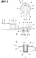
- connecting means 3 Shown and described is, firstly, with reference to Figure 1 , an arrangement of two connecting parts, a first connecting part 1 and a second connecting part 2, for establishing an electrical connection using a, in Figure 2 shown, connecting means 3.
- the first connecting means 1 essentially consists of a first line part 4, which is electrically connected to an end region 5 of a cable 6.
- the second connecting means 2 is formed as an independently manageable component 7, preferably comprising a mounting plate 8 and a second line part 9, which is electrically connected to a second electrical line section 10 exposed to the outside.
- the mounting plate 8 can be provided with fastening recesses 11, preferably in the form of bores, via which, for example, a screw fastening of the component 7 to an assembly, for example a battery, can be achieved.
- the cable 6 of the first connecting part 1 has one or more electrically conductive wires 12 in the center, which are surrounded by an insulating sheath 13 made of an insulating plastic material, for example a radiation-crosslinked polyurethane.
- the cross section of the cable 6 is preferably circular.
- the end of the cable 6 freed from the insulating sheath 13 is electrically connected to the first line part 4.
- the wire or wires 12 can engage in a tubular connection area 14 of the line part 1 (not shown here), for example a crimp section.
- This can be a cable lug. It can also be a connection to a flat conductor, as in the exemplary embodiment shown.
- a compression can be provided to provide electrical conductivity and to mechanically fix the first line part 4 to the cable 6.
- a solder connection of the wires 4 freed from the insulating sheath 13 in this connection area 14 is also possible.
- the first line part 4 can run out freely in the manner of a connection lug and have a bore-like opening 16 exposed to the outside.
- a sleeve-shaped first line section 15 is connected to one side of the first line part 4, surrounding the opening 16. This is preferably connected to the first line part 4 in an electrically conductive manner, for example by soldering.
- a one-piece design of the line part 4 and sleeve 17 to form the first line section 15 is also possible in this regard.
- the first sleeve 17 of the first line part 4 has a sleeve inner wall 18 which runs concentrically to its central axis x and which, in a preferred embodiment, when viewed in the axial direction, runs congruently with the opening edge of the opening 16. It can be a cylindrical surface.
- the contact surface 19 as well as an end face 20 of the first sleeve 17 in the region of its free end facing away from the contact surface 19 extend transversely to the central axis x of the sleeve 17 as well as to the opening 16.
- the first line part 4 is surrounded by an electrically insulating material 21.
- This can, as is also preferred, be a thermoplastic elastomer, which is more preferably applied by overmolding the first line part 4.
- the material 21 surrounds the first line part 4 essentially completely, in particular also surrounding the connection region 14 and the end region 5 of the cable 4, in particular the insulation jacket 13.
- an opening area 22 with an inner diameter that is larger than the opening 16 is formed concentrically to the central axis x in the area facing away from the first sleeve 17. This opening area 22 exposes the aforementioned contact surface 19 of the first line part 4.
- a sealing bead 23 can be formed surrounding the opening edge of the opening area 22.
- the material 21 underpins the first line part 4 until it rests on the sleeve outer wall 24.
- a surrounding surface 25 of the material 21 which surrounds the sleeve 17 and runs essentially at right angles to the central axis x, which is delimited radially on the inside by the sleeve 17 and radially on the outside by a first peripheral wall 26.
- the first peripheral wall 26 is preferably formed in one piece and of the same material as the electrically insulating material 21 and extends, starting from the surrounding surface 25, in the axial direction beyond the end face 20 of the first sleeve 17. This can result in a projection dimension a beyond the end face 20, viewed in the axial direction, which can correspond to approximately 0.15 to 0.2 times the largest inner diameter d of the first peripheral wall 26 (see Figure 3 ).
- the outer surface 27 of this first peripheral wall 26 can, with reference to a section through the peripheral wall 26 according to Figure 3 , in which section the central axis x is represented as a line, starting from the surrounding surface 25, including an angle of preferably 90° to the surrounding surface 25, correspondingly with parallel alignment to the central axis x.
- the corresponding inner surface 28, however, can, as is also preferred, extend conically from the surrounding surface 25 to the free end of the peripheral wall 26. This can result in, for example, an acute angle ⁇ between the inner surface 28 and the surrounding surface 25 of approximately 80° to 85°.
- annular chamber-like immersion region 35 is formed, associated with the surrounding surface 25, according to the above-described arrangement.
- the second line section 10 of the second connecting part 2 can, as also shown, be designed like a sleeve, with an inner wall 29 and an outer wall 30 of the second sleeve 31.
- the sleeve 31 is electrically connected to the second line part 9, for example via a soldered connection or due to a possible one-piece, uniform material design.
- the central opening 46 resulting in the sleeve is preferably pot-shaped and provided with a counter thread 32.
- the counter thread 32 ends in a second end face 33 running transversely to the central axis x' of the second sleeve 31.
- the mounting plate 8 of the component 7 forming the second connecting part 2 can be formed directly by an electrically insulating material 21 or alternatively can be covered or surrounded by it.
- an electrically insulating material 21 Preferably in one piece and of the same material as this material 21, a concentrically arranged the relevant central axis x' is formed with a second peripheral wall 34.
- the peripheral wall 34 preferably lies directly with its inner surface 36 on the facing outer wall 30 of the second sleeve 31.
- the outer surface 37 of the second peripheral wall 34 runs with reference to a sectional view according to Figure 4 at a preferably identical acute angle ⁇ to a plane oriented transversely to the central axis x' as the inner surface 28 of the first peripheral wall 26. This results in a conically tapering course of the outer surface 37 in relation to the outer surface 37 in the direction of the free end of the second peripheral wall 34.
- the second peripheral wall 34 is also designed to extend beyond the associated second end face 33 of the sleeve 31, with a projection dimension a' viewed in the axial direction, which here too can correspond to approximately 0.15 to 0.25 times the inner diameter d' of the second peripheral wall 34.
- the two connecting parts 1 and 2 are brought into a connecting position in the direction of their central axes x and x' (connecting direction R), in particular by plugging the first connecting part 1 onto the second connecting part 2.
- the first peripheral wall 26 of the first connecting part 1 overlaps the second peripheral wall 34 of the second connecting part 2.
- the axial lengths of the peripheral walls 26 and 34 are preferably selected such that in the connecting position they preferably do not come into contact with the facing transverse surface of the opposite connecting part. Instead, a small distance of, for example, a few tenths of a millimeter can be left, which ensures that in the connecting position the end faces 20 and 33 establishing the electrical connection lie against one another over their entire surface.
- both inner diameters d and d' of the peripheral walls 26 and 34 surrounding the line parts 9 and 4 are dimensioned with a diameter of 12.5 mm or less so that before a connection of the connecting parts 1 and 2 is made, each connecting part 1 and 2 has appropriate contact protection in accordance with protection class IP 20.
- connection position (plug-in position) of the connecting parts 1 and 2 is secured by the connecting means 3.
- This is preferably designed in the form of a screw 39 with a screw head 40 and a screw shaft 41.
- the screw shaft 41 has a thread 42 adapted to the mating thread 32 of the second sleeve 31.
- the screw head 40 can, as is also preferred, be surrounded by a further electrically insulating material 21', which can be provided with wrench surfaces 43 on the outside of the wall in the usual way.
- the screw head 40 can have a support section 44 which is otherwise of reduced diameter compared to the screw head 40. In terms of an outer diameter and its axial length, this is essentially adapted to the diameter and the axial height of the opening region 22 of the first connecting part 1 left by the material 21.
- the screw shaft 41 is inserted through the opening area 22 and the opening 16 and accordingly further through the first sleeve 17 for the final screw connection with the second sleeve 31 of the second connecting part 2.
- the support section 44 rests with its free end face preferably over its entire surface and flat on the facing contact surface 19 of the first line section 15, whereby an electrical connection to the second line section 10 can also be achieved via the first line section 15 and the screw 39.
- a tensioning of the connecting parts 1 and 2, in particular their sleeves 17 and 31, against each other in the axial direction is achieved.
- the screw head 40 lies sealingly against the sealing bead 23 of the first connecting part 1 in the region of a step region 45 adjoining the support section 44.
- the first connecting part 1 and the connecting means 3 can be connected in a locking or snap-on manner.
- This connection can, as shown, already be present before a connection is made between the connecting parts 1 and 2, but alternatively it can also only be made during the production process or when the connection position is reached, preferably automatically.
- a region B of the first line part 4 having the opening 16 is provided with a casing 47 made of electrically insulating material 21 surrounding the opening 16, which forms a sealing bead 23 coaxially to the opening 16 and, in the connecting position, optionally also coaxially to a support section 44 of the connecting means 3.
- a locking formation 48 is formed on the connecting part side in the region of the enclosure 47, spaced radially outward from the sealing bead 23, as well as axially from the sealing bead 23 in the direction of the elevation of the sealing bead 23.
- This has a locking recess 54 which is open radially inward and preferably runs all the way around the central axis x.
- a radial distance e between a cross-section according to, for example, Figure 8 resulting zenith of the sealing bead 23 and a radially outer wall of the locking recess 54 which can, for example, correspond to approximately 0.5 to 0.9 times the radial distance g of this zenith region of the sealing bead 23 to the central axis x.
- An axial distance c between the zenith region of the sealing bead 23 and a center of the axial extension of the locking recess 54 viewed in the axial direction can, for example, correspond to approximately 0.15 to 0.5 times the previously described radial distance g.
- the area of the enclosure 47 having the locking formation 48 can be designed as a pot with an insertion opening 55 facing away from the first line part 4 and coaxial with the opening 16.
- a counter-locking formation 49 in the form of a bead section 50 is formed all the way around in the area of the key surfaces 43.
- the counter-locking formation 49 can, as is also preferred, be formed in one piece and of the same material as the rest of the material 21'.
- the counter-locking formation 49 is associated with the lower edge of the material 21', more preferably associated with a possible step region 45.
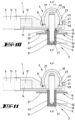
- the connecting means 3 can, as in the Figures 8 and 9 shown, already before the connection is made on the first connecting part 1. In this locking position, the bead section 50 of the connecting means 3 sits in the locking recess 54 of the first connecting part 1.
- the connecting means 3 is designed as a screw 39, the connecting means 3 is freely rotatable about the central axis x (see double arrow f in Figure 8 ), so that in this locking position a screw connection can be made with the second connecting part 2, which then already provides complete insulation to the outside.
- Figure 12 shows a connecting means 3 with a counter-locking formation 49 in the form of a screw 39 with a screw shaft 41 having a thread 42.
- a connecting means 3 serves to produce an electrical connection of the first connecting part 1 with a second connecting part 2 having a threaded bore.
- the connecting means 3 can also, as in Figure 13 shown, be designed in the manner of a screw nut 51 with a screw nut head 56 and a screw shaft receptacle 53 having a counter thread 52.
- Such a connecting means 3 serves to produce an electrical connection of the first connecting part 1 with a second connecting part 2 having a screw shaft.
- a connection which is characterized in that the first and second peripheral walls 26, 34 have an inner diameter d, d' which is 12.5 mm or smaller, that the first and second line sections 10, 15 are designed in the form of a sleeve, with central axes x, x' of the first and second sleeves 17, 31 resulting in the connection direction R, that the connecting means 3 is a screw 39 with a screw head 40 and a screw shaft 41 provided with a thread 42, that the line section 15 and/or the line part 4 of the first connecting part 1 has a contact surface 19 for the screw head 40 and that the 2 formed second sleeve 31 has a counter thread 32 for the screw shaft 41.
- a connection which is characterized in that the second peripheral wall 34 extends radially inside the first peripheral wall 26 in the connected state of the connecting parts 1, 2.
- connection which is characterized in that the end faces 20, 33 lie on one another in the connected state of the connecting parts 1, 2.
- a connection which is characterized in that an insulating material 21 provided surrounding the second sleeve 31 initially rests against the second sleeve 31 and then extends beyond the second end face 33 of the second sleeve 31.
- a connection which is characterized in that the insulating material 21 surrounding the first sleeve 17 below the first end face 20 merges radially outward into a surrounding surface 25 which extends approximately at right angles to the central axis x of the first sleeve 17.
- a connection which is characterized in that, in the connected state, an outer surface 37 of the second peripheral wall 34 cooperates in a sealing manner with an inner surface 28 of the first peripheral wall 26.
- a connecting part which is characterized in that the peripheral wall 26 has an inner diameter d which is 12.5 mm or smaller, that the line section 15 is designed like a sleeve, that the line section 15 has a contact surface 19 for cooperation with a screw head 40 of a screw 39 forming the connecting means 3 in the connected state and that the connecting part 1 forms an end region 5 of a cable 6.
- a connecting part characterized in that the sleeve 17 has a free end face 20.
- a connecting part which is characterized in that the insulating material 21 surrounding the sleeve 17 below the end face 20 merges radially outward into a surrounding surface 25 which extends approximately at right angles to the central axis x of the sleeve 17.
- a connecting part which is characterized in that the surrounding surface 25 is directly limited by the peripheral wall 26.
- a connecting part which is characterized in that the peripheral wall 34 has an inner diameter d' which is 12.5 mm or smaller, that the line section 10 is designed in the form of a sleeve, that the sleeve 31 has a counter thread 32 for screwing a connecting means 3 forming screw 39 and that the connecting part 2 is designed as an independently manageable component 7, with one or more fastening recesses 11.
- a connecting part which is characterized in that the insulating material 21 provided surrounding the sleeve 31 initially rests against the sleeve 31 and then extends beyond the end face 33 of the sleeve 31.
- a connecting part which is characterized in that the enclosure 47 has a locking formation 48 for locking connection with a connecting means 3.
- a connecting part which is characterized in that the enclosure 47 forms a sealing bead 23 and that the locking formation 48 is formed with respect to the central axis x at a radial distance e from the sealing bead 23.
- a connecting part which is characterized in that the locking formation 48, the sealing bead 23, is formed axially spaced from the sealing bead 23 in the direction of an elevation of the sealing bead 23.
- a combination which is characterized in that the counter-locking formation 49 is designed as a bead section 50 projecting radially outwards.
- a combination which is characterized in that the counter-locking formation 49 is made of an electrically insulating material 21'.
- the connecting means 3 is a screw nut 51 with a screw shaft receptacle 53 having a counter thread 52.
- connection means 3 is a screw 39 with a screw head 40 and a screw shaft 41 provided with a thread 42.
- the invention also relates to designs in which individual features mentioned in the above description are not implemented, in particular insofar as they are clearly dispensable for the respective intended use or can be replaced by other technically equivalent means.
Landscapes
- Connector Housings Or Holding Contact Members (AREA)
Applications Claiming Priority (2)
| Application Number | Priority Date | Filing Date | Title |
|---|---|---|---|
| DE202023100290 | 2023-01-20 | ||
| DE202023107478.2U DE202023107478U1 (de) | 2023-01-20 | 2023-12-18 | Elektrische Verbindung, Verbindungsteil einer elektrischen Verbindung sowie Kombination aus einem Verbindungsteil und einem Verbindungsmittel |
Publications (1)
| Publication Number | Publication Date |
|---|---|
| EP4451475A1 true EP4451475A1 (fr) | 2024-10-23 |
Family
ID=89662114
Family Applications (1)
| Application Number | Title | Priority Date | Filing Date |
|---|---|---|---|
| EP24152817.3A Pending EP4451475A1 (fr) | 2023-01-20 | 2024-01-19 | Connexion électrique, pièce de connexion d'une connexion électrique et combinaison d'une pièce de connexion et d'un moyen de connexion |
Country Status (1)
| Country | Link |
|---|---|
| EP (1) | EP4451475A1 (fr) |
Citations (6)
| Publication number | Priority date | Publication date | Assignee | Title |
|---|---|---|---|---|
| DE102013005106B3 (de) | 2013-03-23 | 2014-07-31 | Audi Ag | Steckervorrichtung zum berührsicheren elektrischen Kontaktieren einer korrepondierenden Buchsenvorrichtung, korrespondierende Buchsenvorrichtung sowie daraus gebildetes Verbindersystem |
| DE102016100978A1 (de) | 2015-03-31 | 2016-10-06 | Jens Trimborn | Kunststoff-Dichtungshülle für eine Leiterverbindung, Verbindungsteil, Abdeckmutter sowie abgedichtete Verbindung zwischen zwei Leitern |
| DE102016206378A1 (de) * | 2016-04-15 | 2017-10-19 | Bayerische Motoren Werke Aktiengesellschaft | Verbindungsanordnung eines ersten Bauelements an einem zweiten Bauelement, insbesondere für ein Fahrzeug, sowie Verbindungsvorrichtung, insbesondere für ein Fahrzeug |
| DE202018100111U1 (de) * | 2017-06-21 | 2018-09-24 | Te Connectivity Germany Gmbh | Modulverbinder |
| US20200259400A1 (en) * | 2017-10-31 | 2020-08-13 | Denso Corporation | Rotating electric machine for vehicle |
| DE102020208149A1 (de) * | 2020-06-30 | 2021-12-30 | Te Connectivity Germany Gmbh | Modulverbinder |
-
2024
- 2024-01-19 EP EP24152817.3A patent/EP4451475A1/fr active Pending
Patent Citations (6)
| Publication number | Priority date | Publication date | Assignee | Title |
|---|---|---|---|---|
| DE102013005106B3 (de) | 2013-03-23 | 2014-07-31 | Audi Ag | Steckervorrichtung zum berührsicheren elektrischen Kontaktieren einer korrepondierenden Buchsenvorrichtung, korrespondierende Buchsenvorrichtung sowie daraus gebildetes Verbindersystem |
| DE102016100978A1 (de) | 2015-03-31 | 2016-10-06 | Jens Trimborn | Kunststoff-Dichtungshülle für eine Leiterverbindung, Verbindungsteil, Abdeckmutter sowie abgedichtete Verbindung zwischen zwei Leitern |
| DE102016206378A1 (de) * | 2016-04-15 | 2017-10-19 | Bayerische Motoren Werke Aktiengesellschaft | Verbindungsanordnung eines ersten Bauelements an einem zweiten Bauelement, insbesondere für ein Fahrzeug, sowie Verbindungsvorrichtung, insbesondere für ein Fahrzeug |
| DE202018100111U1 (de) * | 2017-06-21 | 2018-09-24 | Te Connectivity Germany Gmbh | Modulverbinder |
| US20200259400A1 (en) * | 2017-10-31 | 2020-08-13 | Denso Corporation | Rotating electric machine for vehicle |
| DE102020208149A1 (de) * | 2020-06-30 | 2021-12-30 | Te Connectivity Germany Gmbh | Modulverbinder |
Similar Documents
| Publication | Publication Date | Title |
|---|---|---|
| DE10016943C2 (de) | Abschirmverbindungselement | |
| DE60225672T2 (de) | Kabelverschraubungszusammenbau | |
| DE102018009206B3 (de) | Verbindungsbauteil zur Verbindung von elektrischen Leitern einer hairpin-Wicklung eines Stators einer Elektromaschine sowie Verfahren zur Herstellung dieser Verbindung | |
| DE3823617C2 (fr) | ||
| EP0754357B1 (fr) | Systeme de connexion pour conducteurs electriques | |
| DE69328662T2 (de) | Filterverbinder hoher Dichte | |
| DE4226904C2 (de) | Crimphülse | |
| EP3767750A1 (fr) | Connecteur enfichable électrique, élément de protection isolant et procédé de montage d'un connecteur enfichable électrique | |
| DE102004062378B4 (de) | Kabeldurchführungs-Struktur und Kabelbaum | |
| EP3688851B1 (fr) | Passe-câble à vis | |
| EP2551978B1 (fr) | Dispositif d'acheminement d'une ligne électrique au travers d'un boîtier | |
| DE102022122506A1 (de) | Universell einsetzbares Gehäuse zur Abdeckung von Kontaktelementen | |
| EP2945226B1 (fr) | Connecteur et procédé | |
| EP3633802A1 (fr) | Prise de courant d'appareil, connecteur d'appareil et système de connecteur d'appareil | |
| WO1994023481A1 (fr) | Armature pour conducteurs de reseau d'alimentation en energie haute tension et son procede de fabrication | |
| EP0415136B1 (fr) | Insert pour connecteur à boîtier métallique | |
| EP4451475A1 (fr) | Connexion électrique, pièce de connexion d'une connexion électrique et combinaison d'une pièce de connexion et d'un moyen de connexion | |
| DE202023107478U1 (de) | Elektrische Verbindung, Verbindungsteil einer elektrischen Verbindung sowie Kombination aus einem Verbindungsteil und einem Verbindungsmittel | |
| DE10237666B4 (de) | Steckverbinderelement | |
| DE102023004088A1 (de) | Koaxialverbinder | |
| DE202023100299U1 (de) | Elektrischer Verbinder mit integriertem Berührschutz | |
| EP2993737B1 (fr) | Dispositif de connexion a fiches haute frequence, en particulier dispositif de connexion coaxial pour des prises d'antenne | |
| DE3302924C3 (de) | Elektrische Steckverbindung | |
| DE2841676A1 (de) | Koaxiale steckbuchse | |
| DE102021102778A1 (de) | Abschirmfederkontakt, Steckverbinder mit einem Abschirmfederkontakt und Steckverbindersystem mit einem Abschirmfederkontakt |
Legal Events
| Date | Code | Title | Description |
|---|---|---|---|
| PUAI | Public reference made under article 153(3) epc to a published international application that has entered the european phase |
Free format text: ORIGINAL CODE: 0009012 |
|
| STAA | Information on the status of an ep patent application or granted ep patent |
Free format text: STATUS: THE APPLICATION HAS BEEN PUBLISHED |
|
| AK | Designated contracting states |
Kind code of ref document: A1 Designated state(s): AL AT BE BG CH CY CZ DE DK EE ES FI FR GB GR HR HU IE IS IT LI LT LU LV MC ME MK MT NL NO PL PT RO RS SE SI SK SM TR |
|
| STAA | Information on the status of an ep patent application or granted ep patent |
Free format text: STATUS: REQUEST FOR EXAMINATION WAS MADE |
|
| 17P | Request for examination filed |
Effective date: 20250423 |