EP4454868A1 - Rundsonotrode mit intern geklemmter teileaufnahme - Google Patents
Rundsonotrode mit intern geklemmter teileaufnahme Download PDFInfo
- Publication number
- EP4454868A1 EP4454868A1 EP23169585.9A EP23169585A EP4454868A1 EP 4454868 A1 EP4454868 A1 EP 4454868A1 EP 23169585 A EP23169585 A EP 23169585A EP 4454868 A1 EP4454868 A1 EP 4454868A1
- Authority
- EP
- European Patent Office
- Prior art keywords
- sonotrode
- round
- mandrel
- spreading element
- dowel
- Prior art date
- Legal status (The legal status is an assumption and is not a legal conclusion. Google has not performed a legal analysis and makes no representation as to the accuracy of the status listed.)
- Pending
Links
Images




Classifications
-
- B—PERFORMING OPERATIONS; TRANSPORTING
- B29—WORKING OF PLASTICS; WORKING OF SUBSTANCES IN A PLASTIC STATE IN GENERAL
- B29C—SHAPING OR JOINING OF PLASTICS; SHAPING OF MATERIAL IN A PLASTIC STATE, NOT OTHERWISE PROVIDED FOR; AFTER-TREATMENT OF THE SHAPED PRODUCTS, e.g. REPAIRING
- B29C65/00—Joining or sealing of preformed parts, e.g. welding of plastics materials; Apparatus therefor
- B29C65/78—Means for handling the parts to be joined, e.g. for making containers or hollow articles, e.g. means for handling sheets, plates, web-like materials, tubular articles, hollow articles or elements to be joined therewith; Means for discharging the joined articles from the joining apparatus
- B29C65/7802—Positioning the parts to be joined, e.g. aligning, indexing or centring
- B29C65/7805—Positioning the parts to be joined, e.g. aligning, indexing or centring the parts to be joined comprising positioning features
- B29C65/7808—Positioning the parts to be joined, e.g. aligning, indexing or centring the parts to be joined comprising positioning features in the form of holes or slots
- B29C65/7811—Positioning the parts to be joined, e.g. aligning, indexing or centring the parts to be joined comprising positioning features in the form of holes or slots for centring purposes
-
- B—PERFORMING OPERATIONS; TRANSPORTING
- B29—WORKING OF PLASTICS; WORKING OF SUBSTANCES IN A PLASTIC STATE IN GENERAL
- B29C—SHAPING OR JOINING OF PLASTICS; SHAPING OF MATERIAL IN A PLASTIC STATE, NOT OTHERWISE PROVIDED FOR; AFTER-TREATMENT OF THE SHAPED PRODUCTS, e.g. REPAIRING
- B29C65/00—Joining or sealing of preformed parts, e.g. welding of plastics materials; Apparatus therefor
- B29C65/02—Joining or sealing of preformed parts, e.g. welding of plastics materials; Apparatus therefor by heating, with or without pressure
- B29C65/08—Joining or sealing of preformed parts, e.g. welding of plastics materials; Apparatus therefor by heating, with or without pressure using ultrasonic vibrations
-
- B—PERFORMING OPERATIONS; TRANSPORTING
- B29—WORKING OF PLASTICS; WORKING OF SUBSTANCES IN A PLASTIC STATE IN GENERAL
- B29C—SHAPING OR JOINING OF PLASTICS; SHAPING OF MATERIAL IN A PLASTIC STATE, NOT OTHERWISE PROVIDED FOR; AFTER-TREATMENT OF THE SHAPED PRODUCTS, e.g. REPAIRING
- B29C65/00—Joining or sealing of preformed parts, e.g. welding of plastics materials; Apparatus therefor
- B29C65/78—Means for handling the parts to be joined, e.g. for making containers or hollow articles, e.g. means for handling sheets, plates, web-like materials, tubular articles, hollow articles or elements to be joined therewith; Means for discharging the joined articles from the joining apparatus
- B29C65/7802—Positioning the parts to be joined, e.g. aligning, indexing or centring
- B29C65/7838—Positioning the parts to be joined, e.g. aligning, indexing or centring from the inside, e.g. of tubular or hollow articles
-
- B—PERFORMING OPERATIONS; TRANSPORTING
- B29—WORKING OF PLASTICS; WORKING OF SUBSTANCES IN A PLASTIC STATE IN GENERAL
- B29C—SHAPING OR JOINING OF PLASTICS; SHAPING OF MATERIAL IN A PLASTIC STATE, NOT OTHERWISE PROVIDED FOR; AFTER-TREATMENT OF THE SHAPED PRODUCTS, e.g. REPAIRING
- B29C65/00—Joining or sealing of preformed parts, e.g. welding of plastics materials; Apparatus therefor
- B29C65/78—Means for handling the parts to be joined, e.g. for making containers or hollow articles, e.g. means for handling sheets, plates, web-like materials, tubular articles, hollow articles or elements to be joined therewith; Means for discharging the joined articles from the joining apparatus
- B29C65/7841—Holding or clamping means for handling purposes
- B29C65/7844—Holding or clamping means for handling purposes cooperating with specially formed features of at least one of the parts to be joined, e.g. cooperating with holes or ribs of at least one of the parts to be joined
-
- B—PERFORMING OPERATIONS; TRANSPORTING
- B29—WORKING OF PLASTICS; WORKING OF SUBSTANCES IN A PLASTIC STATE IN GENERAL
- B29C—SHAPING OR JOINING OF PLASTICS; SHAPING OF MATERIAL IN A PLASTIC STATE, NOT OTHERWISE PROVIDED FOR; AFTER-TREATMENT OF THE SHAPED PRODUCTS, e.g. REPAIRING
- B29C66/00—General aspects of processes or apparatus for joining preformed parts
- B29C66/01—General aspects dealing with the joint area or with the area to be joined
- B29C66/05—Particular design of joint configurations
- B29C66/10—Particular design of joint configurations particular design of the joint cross-sections
- B29C66/11—Joint cross-sections comprising a single joint-segment, i.e. one of the parts to be joined comprising a single joint-segment in the joint cross-section
- B29C66/112—Single lapped joints
-
- B—PERFORMING OPERATIONS; TRANSPORTING
- B29—WORKING OF PLASTICS; WORKING OF SUBSTANCES IN A PLASTIC STATE IN GENERAL
- B29C—SHAPING OR JOINING OF PLASTICS; SHAPING OF MATERIAL IN A PLASTIC STATE, NOT OTHERWISE PROVIDED FOR; AFTER-TREATMENT OF THE SHAPED PRODUCTS, e.g. REPAIRING
- B29C66/00—General aspects of processes or apparatus for joining preformed parts
- B29C66/01—General aspects dealing with the joint area or with the area to be joined
- B29C66/05—Particular design of joint configurations
- B29C66/10—Particular design of joint configurations particular design of the joint cross-sections
- B29C66/11—Joint cross-sections comprising a single joint-segment, i.e. one of the parts to be joined comprising a single joint-segment in the joint cross-section
- B29C66/114—Single butt joints
-
- B—PERFORMING OPERATIONS; TRANSPORTING
- B29—WORKING OF PLASTICS; WORKING OF SUBSTANCES IN A PLASTIC STATE IN GENERAL
- B29C—SHAPING OR JOINING OF PLASTICS; SHAPING OF MATERIAL IN A PLASTIC STATE, NOT OTHERWISE PROVIDED FOR; AFTER-TREATMENT OF THE SHAPED PRODUCTS, e.g. REPAIRING
- B29C66/00—General aspects of processes or apparatus for joining preformed parts
- B29C66/01—General aspects dealing with the joint area or with the area to be joined
- B29C66/05—Particular design of joint configurations
- B29C66/10—Particular design of joint configurations particular design of the joint cross-sections
- B29C66/13—Single flanged joints; Fin-type joints; Single hem joints; Edge joints; Interpenetrating fingered joints; Other specific particular designs of joint cross-sections not provided for in groups B29C66/11 - B29C66/12
- B29C66/131—Single flanged joints, i.e. one of the parts to be joined being rigid and flanged in the joint area
-
- B—PERFORMING OPERATIONS; TRANSPORTING
- B29—WORKING OF PLASTICS; WORKING OF SUBSTANCES IN A PLASTIC STATE IN GENERAL
- B29C—SHAPING OR JOINING OF PLASTICS; SHAPING OF MATERIAL IN A PLASTIC STATE, NOT OTHERWISE PROVIDED FOR; AFTER-TREATMENT OF THE SHAPED PRODUCTS, e.g. REPAIRING
- B29C66/00—General aspects of processes or apparatus for joining preformed parts
- B29C66/01—General aspects dealing with the joint area or with the area to be joined
- B29C66/05—Particular design of joint configurations
- B29C66/20—Particular design of joint configurations particular design of the joint lines, e.g. of the weld lines
- B29C66/24—Particular design of joint configurations particular design of the joint lines, e.g. of the weld lines said joint lines being closed or non-straight
- B29C66/242—Particular design of joint configurations particular design of the joint lines, e.g. of the weld lines said joint lines being closed or non-straight said joint lines being closed, i.e. forming closed contours
- B29C66/2422—Particular design of joint configurations particular design of the joint lines, e.g. of the weld lines said joint lines being closed or non-straight said joint lines being closed, i.e. forming closed contours being circular, oval or elliptical
- B29C66/24221—Particular design of joint configurations particular design of the joint lines, e.g. of the weld lines said joint lines being closed or non-straight said joint lines being closed, i.e. forming closed contours being circular, oval or elliptical being circular
-
- B—PERFORMING OPERATIONS; TRANSPORTING
- B29—WORKING OF PLASTICS; WORKING OF SUBSTANCES IN A PLASTIC STATE IN GENERAL
- B29C—SHAPING OR JOINING OF PLASTICS; SHAPING OF MATERIAL IN A PLASTIC STATE, NOT OTHERWISE PROVIDED FOR; AFTER-TREATMENT OF THE SHAPED PRODUCTS, e.g. REPAIRING
- B29C66/00—General aspects of processes or apparatus for joining preformed parts
- B29C66/40—General aspects of joining substantially flat articles, e.g. plates, sheets or web-like materials; Making flat seams in tubular or hollow articles; Joining single elements to substantially flat surfaces
- B29C66/47—Joining single elements to sheets, plates or other substantially flat surfaces
- B29C66/474—Joining single elements to sheets, plates or other substantially flat surfaces said single elements being substantially non-flat
-
- B—PERFORMING OPERATIONS; TRANSPORTING
- B29—WORKING OF PLASTICS; WORKING OF SUBSTANCES IN A PLASTIC STATE IN GENERAL
- B29C—SHAPING OR JOINING OF PLASTICS; SHAPING OF MATERIAL IN A PLASTIC STATE, NOT OTHERWISE PROVIDED FOR; AFTER-TREATMENT OF THE SHAPED PRODUCTS, e.g. REPAIRING
- B29C66/00—General aspects of processes or apparatus for joining preformed parts
- B29C66/50—General aspects of joining tubular articles; General aspects of joining long products, i.e. bars or profiled elements; General aspects of joining single elements to tubular articles, hollow articles or bars; General aspects of joining several hollow-preforms to form hollow or tubular articles
- B29C66/51—Joining tubular articles, profiled elements or bars; Joining single elements to tubular articles, hollow articles or bars; Joining several hollow-preforms to form hollow or tubular articles
- B29C66/53—Joining single elements to tubular articles, hollow articles or bars
- B29C66/532—Joining single elements to the wall of tubular articles, hollow articles or bars
- B29C66/5324—Joining single elements to the wall of tubular articles, hollow articles or bars said single elements being substantially annular, i.e. of finite length
-
- B—PERFORMING OPERATIONS; TRANSPORTING
- B29—WORKING OF PLASTICS; WORKING OF SUBSTANCES IN A PLASTIC STATE IN GENERAL
- B29C—SHAPING OR JOINING OF PLASTICS; SHAPING OF MATERIAL IN A PLASTIC STATE, NOT OTHERWISE PROVIDED FOR; AFTER-TREATMENT OF THE SHAPED PRODUCTS, e.g. REPAIRING
- B29C66/00—General aspects of processes or apparatus for joining preformed parts
- B29C66/50—General aspects of joining tubular articles; General aspects of joining long products, i.e. bars or profiled elements; General aspects of joining single elements to tubular articles, hollow articles or bars; General aspects of joining several hollow-preforms to form hollow or tubular articles
- B29C66/61—Joining from or joining on the inside
-
- B—PERFORMING OPERATIONS; TRANSPORTING
- B29—WORKING OF PLASTICS; WORKING OF SUBSTANCES IN A PLASTIC STATE IN GENERAL
- B29C—SHAPING OR JOINING OF PLASTICS; SHAPING OF MATERIAL IN A PLASTIC STATE, NOT OTHERWISE PROVIDED FOR; AFTER-TREATMENT OF THE SHAPED PRODUCTS, e.g. REPAIRING
- B29C66/00—General aspects of processes or apparatus for joining preformed parts
- B29C66/80—General aspects of machine operations or constructions and parts thereof
- B29C66/81—General aspects of the pressing elements, i.e. the elements applying pressure on the parts to be joined in the area to be joined, e.g. the welding jaws or clamps
- B29C66/814—General aspects of the pressing elements, i.e. the elements applying pressure on the parts to be joined in the area to be joined, e.g. the welding jaws or clamps characterised by the design of the pressing elements, e.g. of the welding jaws or clamps
- B29C66/8141—General aspects of the pressing elements, i.e. the elements applying pressure on the parts to be joined in the area to be joined, e.g. the welding jaws or clamps characterised by the design of the pressing elements, e.g. of the welding jaws or clamps characterised by the surface geometry of the part of the pressing elements, e.g. welding jaws or clamps, coming into contact with the parts to be joined
- B29C66/81431—General aspects of the pressing elements, i.e. the elements applying pressure on the parts to be joined in the area to be joined, e.g. the welding jaws or clamps characterised by the design of the pressing elements, e.g. of the welding jaws or clamps characterised by the surface geometry of the part of the pressing elements, e.g. welding jaws or clamps, coming into contact with the parts to be joined comprising a single cavity, e.g. a groove
-
- B—PERFORMING OPERATIONS; TRANSPORTING
- B29—WORKING OF PLASTICS; WORKING OF SUBSTANCES IN A PLASTIC STATE IN GENERAL
- B29C—SHAPING OR JOINING OF PLASTICS; SHAPING OF MATERIAL IN A PLASTIC STATE, NOT OTHERWISE PROVIDED FOR; AFTER-TREATMENT OF THE SHAPED PRODUCTS, e.g. REPAIRING
- B29C66/00—General aspects of processes or apparatus for joining preformed parts
- B29C66/80—General aspects of machine operations or constructions and parts thereof
- B29C66/83—General aspects of machine operations or constructions and parts thereof characterised by the movement of the joining or pressing tools
- B29C66/832—Reciprocating joining or pressing tools
- B29C66/8322—Joining or pressing tools reciprocating along one axis
-
- B—PERFORMING OPERATIONS; TRANSPORTING
- B29—WORKING OF PLASTICS; WORKING OF SUBSTANCES IN A PLASTIC STATE IN GENERAL
- B29L—INDEXING SCHEME ASSOCIATED WITH SUBCLASS B29C, RELATING TO PARTICULAR ARTICLES
- B29L2031/00—Other particular articles
- B29L2031/30—Vehicles, e.g. ships or aircraft, or body parts thereof
- B29L2031/3044—Bumpers
-
- B—PERFORMING OPERATIONS; TRANSPORTING
- B29—WORKING OF PLASTICS; WORKING OF SUBSTANCES IN A PLASTIC STATE IN GENERAL
- B29L—INDEXING SCHEME ASSOCIATED WITH SUBCLASS B29C, RELATING TO PARTICULAR ARTICLES
- B29L2031/00—Other particular articles
- B29L2031/737—Articles provided with holes, e.g. grids, sieves
Definitions
- the invention relates to a round sonotrode for an ultrasonic welding system for welding two components by means of ultrasound, comprising an annular welding area and a receiving mandrel for receiving a component to be welded.
- Round sonotrodes for welding two plastic components in particular for attaching a holder for ultrasonic distance sensors, so-called parking distance control (PDC) sensors, to the inside of a bumper are well known.
- PDC parking distance control
- One challenge is to securely connect the holder to the bumper without damaging the already painted outside of the bumper.
- the holder must be aligned with respect to a recess in the bumper in which the sensor is attached and welded in this position.
- Round sonotrodes which are also known as ring sonotrodes, have become established for such welding tasks.
- DE 10 2014 212 313 A1 A cup-shaped torsion sonotrode is known which is excited to torsional ultrasonic vibrations around a central torsion axis.
- a positioning device is mounted in the central torsion axis, which is screwed to the bottom of the recess.
- a radially resonant, cup-shaped sonotrode, in which a positioning element is mounted force-fittingly in the bottom of the cup-shaped recess is known from DE 20 2017 104 190 U1 known.
- Such concepts have shown that welding plastic components using round sonotrodes leads to very good results.
- screwing the positioning device centrally at the bottom of the cup-shaped recess is disadvantageous, since even if the screw connection of the positioning element is arranged in a vibration node, friction occurs in the threaded connection. This can lead to increased wear and tear as well as to the screw connection becoming loose.
- the object of the present invention is to provide a round sonotrode with a receiving mandrel which is improved with regard to its vibration properties and which can be designed as a longitudinally vibrating sonotrode.
- the round sonotrode according to the invention for an ultrasonic welding system for welding two components has a sonotrode body extending in a longitudinal direction with a central recess. An annular welding area is arranged on a first end face of the sonotrode body. A receiving mandrel for receiving a first of the two components to be welded is arranged in the central recess. The receiving mandrel is held in the central recess by means of a spreading element that is deformed during assembly.
- the sonotrode body is usually designed to be essentially rotationally symmetrical about a central longitudinal axis extending in the longitudinal direction.
- the mandrel extends along the central axis so that the ring-shaped welding area, the central recess and the mandrel are designed to be concentric with one another.
- the welding area can be equipped with axially protruding knobs, for example, which penetrate into the plastic of the components to be welded and heat it to a welding temperature using ultrasonic vibrations.
- the mandrel can fulfil various functions.
- a first function can be to pick up and hold a first component to be welded, such as a holder for an ultrasonic distance sensor.
- the mandrel has an outer contour that corresponds to an inner contour of the first component, so that the first component to be welded receives the mandrel in its interior and surrounds it.
- the first component to be welded thus has a central opening or hole so that it can be pushed onto the mandrel.
- Another function can lie in the rotational alignment of the first component to be welded.
- the outer contour of the mandrel and the complementary inner contour of the first component to be welded not being rotationally symmetrical, but having radial projections or recesses to ensure a clear rotationally symmetrical alignment of the first component.
- the mandrel must also be rotationally fixed and arranged in a predetermined rotational position relative to the sonotrode body or the ultrasonic welding system.
- a third function of the mandrel can be that the second component on the mandrel, for example a bumper, is aligned or centered on the mandrel.
- the mandrel is held in the central recess by the expansion element, which is deformed during assembly.
- the expansion element By connecting the mandrel to the sonotrode body using the expansion element, a firm connection is established between the mandrel and the sonotrode body. This connection is established by deforming the expansion element during assembly of the expansion element in the sonotrode body. During assembly, the expansion element is deformed radially outwards and is thus braced or clamped in the recess. This creates a force-fit connection between the expansion element and the sonotrode body.
- the expansion element is preferably designed as a metal element.
- a firm connection is preferably understood to mean that it is not an elastic or oscillating suspension of the mandrel in the sonotrode body, as for example in DE 10 2014 111 661 A1
- vibration-decoupled suspensions via elastomers or rubber elements should not be understood as fixed suspensions in the sense of the invention.
- the spreading element is preferably arranged in the area of a node surface of the round sonotrode.
- a node surface is understood to be a surface perpendicular to the sonotrode axis in which the vibration amplitude is minimal.
- the sonotrode body can have one or more node surfaces.
- the node surface extends radially outwards over the entire sonotrode body.
- the node surface does not run purely radially outwards, but can also be a surface that runs curved outwards.
- the expansion element is preferably plastically deformed.
- the plastic deformation can be achieved by deforming areas of the outer contour of the expansion element by pressing them against the inner contour of the recess in the sonotrode body in such a way that a plastically (and thus permanently) deformed connection surface is created.
- Plastic deformation is understood to mean in particular a deformation that leads to at least a local exceedance of the material-dependent yield strength R p0.2 .
- the plastic deformation preferably occurs in the area of the outer surface of the expansion element that is in contact with the sonotrode body. The deformation is less than the maximum permissible compressive stress, i.e.
- the maximum permissible compressive stresses of the material of the expansion element are preferably used in order to create a secure connection between the expansion element and the sonotrode body.
- a secure connection is also understood to mean in particular that the expansion element and thus the holding mandrel are held securely in position during operation of the sonotrode, i.e. in a vibration state excited at the natural frequency of the sonotrode.
- other areas of the expansion element can also be plastically deformed. For example, when the expansion element is spread radially, plastic deformation can occur in such a way that the expansion element is plastically deformed into a spread position.
- the cone can also be plastically deformed during assembly.
- the expansion element is preferably designed in the manner of a dowel.
- it preferably has a conical inner surface and the dowel and thus the entire expansion element are expanded by a driven-in cone.
- the cone is introduced into the dowel under force so that the expansion element expands radially outwards.
- the cone thus has the function of a three-dimensional wedge which expands the dowel in all directions.
- the cone and the conical inner surface preferably have congruent surface contours at least in some areas.
- the cone has at least one conical section in the form of a truncated cone, but can also be designed as a cone with a tip.
- the cone angle and the cone angle of the conical inner surface are preferably designed in such a way that self-locking occurs.
- Self-locking occurs when the cone is inserted into the dowel under force and engages with the conical inner surface.
- the self-locking prevents the cone from slipping out of the conical section in the opposite direction to the insertion direction. It prevents the clamping connection between the expansion element and the sonotrode body from coming loose, especially when the sonotrode is in operation.
- the cone can be fixed mechanically.
- the cone can be fixed in its position after assembly using a screw that is screwed lengthwise into the expansion element, i.e. in the direction in which the cone is inserted, and that is in contact with a base surface of the cone. This also effectively prevents the cone from moving out.
- the screw can also be fixed using known means such as gluing or mechanical screw locking.
- the expansion element preferably has at least one longitudinal slot.
- the at least one longitudinal slot preferably extends over a section in the longitudinal extension of the expansion element and enables simplified radial expansion of the same.
- the at least one longitudinal slot is preferably introduced into the dowel in the region of the conical inner surface and allows radial expansion of the same when the cone is introduced.
- the expansion element preferably has two, three, four or more longitudinal slots, which are preferably evenly distributed over the entire circumference of the expansion element, i.e. are arranged offset from one another by the same angular amount.
- the conical inner surface of the expansion element is preferably designed such that the conicity extends along the longitudinal axis.
- the conical inner surface of the expansion element can thus be open towards the first end face, i.e. towards the welding area, and enlarge, or open towards an opposite second end face and enlarge.
- the conical inner surface and the cone should also include surface shapes that taper in the driving-in direction of the cone, but are not strictly conical, such as convex or concave tapering surfaces.
- the cone is preferably introduced into the sonotrode body on the first end face, whereas in the second alternative the cone is usually introduced on the side of the second end face.
- the expansion element preferably has at least one radial projection.
- the radial projection is arranged on an outer side of the expansion element, in particular radially outside the conical inner surface, and extends outwards.
- the radial projection is preferably circumferential, i.e. annular, on a cylindrical outer contour of the expansion element.
- the expansion element has a cylindrical shape with radially outwardly extending annular projections.
- the at least one circumferential projection can be interrupted by the longitudinal slots.
- the at least one radial projection is preferably arranged in the node surface. If there are a large number of radial projections on the expansion element, a radial projection of the large number of projections facing the first end face is preferably arranged in the node surface. The other projections are thus arranged further away from the welding area and offset in the direction of the second end face. This has the advantage that the clamping area, which is arranged closest to a tip of the mandrel, is in the area of the smallest vibration amplitude.
- the at least one radial projection preferably engages in a bulge in the central recess.
- the at least one projection can have a surface that is partially convex or parabolically curved outwards.
- the bulge preferably has a cross-section that is essentially congruent in shape to that of the radial projection. In a design with a single circumferential projection, this can have an essentially round, in particular essentially semicircular, cross-section that extends radially outwards.
- the circumferential projection can be interrupted by longitudinal slots.
- the projection engages in a circumferential bulge, for example in the form of a groove, which is worked into the surface of the central recess.
- the groove is circumferential and preferably also has a semicircular cross-section.
- radial projections these are preferably designed as essentially hemispherical projections.
- the projections are preferably arranged axially in an identical position on the expansion element and evenly distributed around the circumference. If there are a large number of projections that have a circular cross-section in a projection in the radial direction, the bulge can be designed as radial holes in the sonotrode body. This has the advantage that in addition to axial positioning of the expansion element and the receiving mandrel, rotational positioning also takes place.
- the at least one projection can snap into the recess for positioning.
- the expansion element is then expanded, for example by inserting the cone, and is thereby fixed in the sonotrode body. During expansion, the surface of at least one projection is preferably plastically deformed. In addition, the expansion element is held in its position by the bulge, not (exclusively) frictionally, but rather positively.
- the mandrel is screwed to the expansion element.
- no vibrations are transferred to the mandrel by clamping the expansion element.
- the screw connection of the mandrel is arranged in an area that has no or only minimal vibrations, and thus the screw connection does not come loose during operation or leads to a reduced service life of the components in the thread area. Loosening can of course also be prevented by common screw locking methods.
- the mandrel is preferably designed in several parts and has at least one mandrel element which is arranged on a bolt so that it can move in the longitudinal direction of the round sonotrode.
- the bolt is therefore preferably connected to the expansion element, preferably screwed, and the mandrel element is guided so that it can move on the bolt.
- the mandrel element preferably has a recess into which the bolt engages.
- the bolt can be cylindrical and not rotationally symmetrical at least in the area of the mandrel element guide, so that twisting of the mandrel element is prevented.
- the mandrel element is also preferably prestressed in the longitudinal direction away from the expansion element via a prestressing element.
- the mandrel element which receives the first component to be welded, to prestress it relative to the second component to be welded before the welding area of the round sonotrode engages with the first component to be welded.
- This means that the first component to be welded is held securely on the second component to be welded, particularly during the welding process, and is positioned and fixed relative to it. Due to the low-vibration mounting of the expansion element, no or only low amplitudes are transferred to the mandrel element even during operation during the welding process, thus ensuring a secure fixation of the first component to the second component.
- the mandrel element is designed to hold the first component, as described above with respect to the holding mandrel. Furthermore, the holding mandrel can have other functions such as the rotational alignment of the first component and centering of the second component.
- the round sonotrode is preferably designed as a longitudinally resonant round sonotrode.
- the resonance of the sonotrode body is particularly crucial for this.
- the sonotrode body can be adapted to vibration properties, in particular to the resonance frequency for ultrasonic welding.
- the round sonotrode is excited to vibrate in the longitudinal direction by a sound generator at its resonance frequency.
- the longitudinally resonant round sonotrode is preferably dimensioned such that the sonotrode body preferably has the length of a full wavelength.
- the sonotrode body is preferably connected to the sound generator on the second end face.
- the sonotrode body preferably has a receptacle for introducing vibrations on the second end face.
- a threaded hole is preferably made in the second end face, by means of which the sonotrode body is screwed onto the sound generator.
- the second end face can represent a contact surface which is in contact with a surface of the sound generator and transmits the vibrations.
- the central recess preferably extends longitudinally over the entire sonotrode body.
- the sonotrode body is thus designed as a hollow cylinder, whereby both the inner and outer diameters can vary over its length.
- the inner cavity thus extends from the central recess in the welding area over a cylindrical area in which the expansion element is arranged, to the threaded hole by means of which the round sonotrode or the sonotrode body is screwed to the sound transducer.
- the round sonotrode comprises two node surfaces.
- the sonotrode body also comprises three areas with vibration maxima, namely in the area of vibration introduction on the second surface, in the welding area on the first surface and in between.
- Typical vibration maxima for sonotrodes for welding two plastic components made of polypropylene are approximately 25 ⁇ m at an excitation frequency of 35 kHz.
- the areas of the amplitude maxima are at the beginning and end as well as halfway along the sonotrode body and the node surfaces at one quarter and three quarters of the length of the sonotrode body.
- the expansion element is preferably arranged in a node surface facing away from the first end face or a node surface facing the second end face. As a result, the expansion element is arranged further away from the welding area and closer to the fastening area via which the vibrations are introduced.
- the expansion element is preferably made of a softer material than the sonotrode body. This applies in particular to the dowel of the expansion element.
- the sonotrode body is preferably made of a titanium alloy, a tool steel or a high-strength aluminum alloy. Brass is preferably used as the softer material for the expansion element.
- the expansion element and in particular the brass dowel are expanded, the latter is plastically deformed on the inner surface of the sonotrode body.
- the expansion element and in particular the brass dowel are expanded, the latter is plastically deformed on the inner surface of the sonotrode body.
- the clamping of the expansion element made of the softer material is usually carried out via a predefined clamping area along the sonotrode body and can, as described above, be accomplished via ring-shaped projections. Thus, sections of the clamping area are also located outside the node area.
- the longitudinal movements in the sonotrode body as well as the resulting transverse contractions of the sonotrode body can be absorbed by the softer material without the vibrations being transferred (in full) to the mandrel.
- the stresses remaining after the plastic deformation of the expansion element are higher than the stresses resulting from the movements in the contact area between the sonotrode and the expansion element.
- there is no relative movement at the contact surfaces between the sonotrode body and the expansion element and the mandrel remains in its position. Nevertheless, there is a firm connection between the sonotrode body and the mandrel, especially in the area of the node surface.
- FIG 1 shows an example of a round sonotrode 1 according to the invention.
- the round sonotrode 1 has a sonotrode body 10.
- a base body of the sonotrode body 10 is rotationally symmetrical about a longitudinal axis L, which can also be referred to as the central axis.
- the sonotrode body 10 has a welding area 14 arranged on a first end face 15 and a fastening area 16 on an opposite, second end face 17.
- the sonotrode body 10 has a central recess 12 on the first end face 15, so that the welding area 14 is designed as a ring shape.
- the central recess 12 is formed over the entire length of the sonotrode body 10, wherein it has a larger diameter on the first end face 15 compared to the second end face 17.
- the recess 12 is designed as a bore with a thread (not shown), so that the sonotrode body 10 can be screwed to a sound transducer (not shown). This lies flat against the second end face 17.
- the sound transducer causes the sonotrode body 10 to vibrate, in particular to vibrate in the direction of the longitudinal axis L.
- a mandrel 40 is fastened in the central recess 12 of the sonotrode body 10 via a spreading element 20.
- the central recess 12 is designed as a bore of constant diameter in the area where the spreading element 20 is arranged.
- the sonotrode body 10 has a length I of a full wavelength. This creates the vibration maxima M 1 , M 0 and M 1/2 in the area of the first and second front sides 15, 17 and at 1 ⁇ 2*I. At 1 ⁇ 4*I and 3 ⁇ 4*I, node points or node surfaces K 1/4 extending radially over the sonotrode body 10 are created. and K 3/4 , in which the vibration is minimal and thus only little or no deformation of the sonotrode body 10 occurs. The node surface does not run exclusively radially outwards, but also has a component in the longitudinal direction.
- the change in diameter of the central recess 12 due to transverse contraction and also the longitudinal vibration are minimal.
- the expansion element 20 is clamped in the node surface K 1/4 in the sonotrode body 10.
- a cone 26 is driven into a dowel 22 with a conical inner surface 24 in such a way that the dowel 22 is spread open and has been plastically deformed.
- an outer surface 23 of the dowel 22 is plastically deformed in such a way that the dowel 22 is clamped in the central recess 12 and is force-fittingly fastened in the sonotrode body 10.
- a bolt 42 of the receiving mandrel 40 is connected to the expansion element 20.
- a mandrel element 44 is arranged on the bolt 42 so that it can move in the direction of the longitudinal axis L.
- the mandrel element 44 is preloaded away from the expansion element 20 by a spring (not shown).
- the receiving mandrel 40 and in particular the mandrel element 44 have the function of receiving or holding the first component 50, for example a sensor holder made of plastic for a PDC sensor.
- the mandrel element 44 has the function of aligning the first component 50 in a rotational manner.
- the first component 50 in the form of a PDC holder is a non-rotationally symmetrical component which is to be welded to the second component 60, for example a bumper made of plastic, in a predefined rotational orientation.
- the mandrel element 44 is also not rotationally symmetrical and has, for example, a radial positioning projection or a radial positioning recess, which is complementary to an inner contour of the first component. Furthermore, the mandrel element 44 is fastened to the bolt 42 in such a way that it is secured against rotation.
- a further function of the mandrel 40 is the centering function of the two components 50, 60.
- the centering function consists in centering an axis of the first component 50 with a circular recess 62 in the second component 60, in particular an opening in the bumper for the PDC sensor, along the longitudinal axis L.
- the first component 50 is initially held on the mandrel 40.
- the round sonotrode 1 is moved relative to the second component 60 in the direction of the longitudinal axis L towards the second component 60.
- the spring (not shown) with which the mandrel element 44 is prestressed generates a prestressing force between the first component 50 and the second component 60.
- the surge converter presses the round sonotrode 1 with a Vibration is excited in one of the longitudinal eigenmodes of the sonotrode body 10 and this is set into resonance. Due to the arrangement of the expansion element 20 at the node point K 1/4 , the vibration transmitted to the mandrel 40 is zero or minimal. This increases the positioning accuracy of the first component 50 and also improves the welding result.
- Figure 3 shows a dowel 22 according to the invention in a first embodiment, as shown for example in Figure 1 can be used.
- Figure 3a shows the dowel 22 in a longitudinal section
- Figure 3b shows a top view of the Figure 3a second end face of the dowel 22 arranged on the left.
- the dowel 22 has a hollow cylindrical basic shape.
- the inner surface of the dowel 22 has the conical region 24 at its end shown on the left.
- the conical region 24 is designed in such a way that it tapers towards the end of the component, i.e. towards the second end face 17 shown in the figure.
- a thread 32 is arranged on the side of the recess 12 opposite the cone 24.
- the receiving mandrel 40 and in particular the bolt 42 of the receiving mandrel 40 can be screwed to the dowel 22 via the thread 32.
- the outer surface 23 of the dowel is essentially cylindrical and has three radial projections 28, 28', 28" in the region of the conical inner surface 24.
- the radial projections 28, 28 ⁇ , 28" are formed as circumferential rings integral with the dowel 22.
- the dowel 22 has longitudinal slots 30, 30', 30", 30′′′ in the area of the conical inner surface 24, which Figure 3b are shown and extend radially over the entire dowel 22.
- the individual longitudinal slots 30, 30', 30", 30′′′ are each arranged offset by 90° from one another.
- the conical inner surface 24 has a cone angle which is designed in such a way that it is a self-locking cone.
- the cone 26 is driven into the conical area 24 of the dowel 22. This is done by applying a predefined force. For this purpose, for example, a screw can be screwed into the thread 32 under a predefined torque.
- a predefined force for this purpose, for example, a screw can be screwed into the thread 32 under a predefined torque.
- the brass dowel 22 expands and in particular the radial projections 28, 28', 28" deform plastically.
- the plastic deformation is facilitated by the four longitudinal slots 30, 30', 30", 30′′′ and an improved pressing of the ring elements is ensured.
- the plastic deformation of the dowel 22 securely fixes the expansion element 20 in the sonotrode body 10.
- the plastic deformation is designed in such a way that the compressive residual stresses of the brass dowel 22 are maximum without leading to failure of the component.
- the sonotrode body 10 is usually made of a titanium alloy. Due to The material of the dowel 22 is softer than that of the sonotrode body 10, meaning that it can absorb the compressive stresses. In addition, the dimensioning of the residual compressive stresses to be introduced must ensure that no friction occurs between the dowel 22 and the sonotrode body 10 due to the induced vibrations, which would lead to wear.
- the third radial projection 28" is arranged in the node surface K 1/4 . No longitudinal vibration occurs in the node surface K 1/4 , but at most minimal transverse contractions of the central recess 12 can occur. However, these can be absorbed and compensated by the plastic deformation of the dowel 22.
- the first and second radial projection 28, 28' are located outside the node surface K 1/4 and thus a longitudinal vibration of the sonotrode body 10 occurs in the area of these projections.
- the plastic deformation of the dowel 22 ensures that no friction occurs between the dowel 22 and the sonotrode body 10. By forming the dowel 22 from a softer material than the sonotrode body 10, it can compensate for the minimal longitudinal vibrations in this area without friction between the projections 28, 28' and the sonotrode body 10. occurs.
- FIG. 4 An alternative embodiment of the anchor 22 is shown in Figure 4 shown.
- Figure 4a shows a cross section and Figure 4b shows a top view of the Figure 4a left-hand side of the dowel 22.
- the conical inner surface 24 does not decrease towards the left side but widens towards the left or narrows starting from the left end face towards the thread 32.
- the cone 26 is not driven in from the direction of the first end face 15 but from the direction of the second end face 17, i.e. the fastening area 16.
- a further thread 32' is arranged in order to drive or press in the cone 26 with a screw. This enables simple and repeatable pressing of the dowel 22 under predefined forces.
- FIG 5 shows a second embodiment of a round sonotrode 1 according to the invention with a mandrel 40.
- the sonotrode body 10 has, in comparison to the one in Figure 1 shown sonotrode body 10 has a bulge in the central recess 12.
- the bulge is designed as a circumferential groove 18.
- the circumferential groove 18 has a convex outwardly curved cross-section.
- the dowel 22 has a radially outwardly extending, circumferential projection 34.
- the projection 34 has an outwardly convex cross-section which is designed essentially congruent to the cross-section of the groove 18.
- Figure 6 shows a dowel 22 according to the invention in a third embodiment, as shown for example in Figure 5 can be used.
- Figure 6a shows the dowel 22 in a longitudinal section
- Figure 6b shows a top view of the Figure 6a second end face of the dowel 22 arranged on the left.
- the projection 34 extending radially away from the cylindrical region of the outer surface 23 of the dowel 22 is designed as a circumferential projection which is interrupted by the longitudinal slots 30-30′′′.
- the dowel 22 When installing the dowel 22, the dowel 22 is first inserted into the recess 12 until the projection 34 snaps into the groove 18. The cone 26 is then inserted and the dowel 22 is spread open. When inserting the cone 26, it may be necessary to elastically deform the individual sections between the longitudinal slots 30-30′′′ radially inwards so that the projection 19 can be inserted into the recess. When spreading, the outer surface 23 and in particular the projection 34 are plastically deformed.
- Figure 7 shows a third embodiment of a round sonotrode 1 according to the invention with a mandrel 40.
- the sonotrode body 10 has, in comparison to the one in Figure 5
- the sonotrode body shown does not have a bulge in the form of a radial groove 18, but rather four or two continuous radial bores 19, so that the sonotrode body 10 contains four bulges.
- the bores 19 are offset from one another by an angle of 90°.
- the dowel 22 has four projections 36-36′′′, which extend outwards in a substantially hemispherical manner.
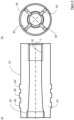
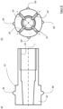
- Figure 8 shows a dowel 22 according to the invention in a fourth embodiment, as shown for example in Figure 7 can be used.
- Figure 8a shows the dowel 22 in a longitudinal section
- Figure 8b shows a top view of the Figure 8a second front side of the dowel 22 arranged on the left.
- the projections 36-36′′′ extending radially away from the cylindrical area of the outer surface 23 of the dowel 22 are offset by an angle of 90° to one another and are arranged centrally between two longitudinal slots 30-30′′′.
- it may also have to be rotated about its longitudinal axis so that the projections 36-36′′′ are aligned with the holes 19 and engage in them.
Landscapes
- Engineering & Computer Science (AREA)
- Mechanical Engineering (AREA)
- Pressure Welding/Diffusion-Bonding (AREA)
Abstract
Description
- Die Erfindung betrifft eine Rundsonotrode für eine Ultraschallschweißanlage zum Verschweißen von zwei Bauteilen mittels Ultraschall, aufweisend einen ringförmigen Schweißbereich und einen Aufnahmedorn zur Aufnahme eines zu verschweißenden Bauteils.
- Rundsonotroden zum Verschweißen von zwei Bauteilen aus Kunststoff, insbesondere zum Anbringen eines Halters für Ultraschall-Abstandssensoren, sogenannte Park-Distance-Control (PDC-)Sensoren, am Innenbereich eines Stoßfängers sind bekannt. Eine Herausforderung besteht darin, die Halter mit dem Stoßfänger sicher zu verbinden, ohne dabei die bereits lackierte Außenseite des Stoßfängers zu beschädigen. Zudem ist der Halter in Bezug auf eine Ausnehmung im Stoßfänger, in welcher der Sensor angebracht wird, auszurichten und in dieser Position zu verschweißen. Für derartige Schweißaufgaben haben sich Rundsonotroden, welche auch als Ringsonotroden bezeichnet werden, etabliert. Aus
DE 10 2014 212 313 A1 ist eine becherförmige Torsionssonotrode bekannt, welche zu torsionalen Ultraschallschwingungen um eine zentrale Torsionsachse angeregt wird. In der zentrale Torsionsachse ist eine Positioniereinrichtung angebracht, welche mit dem Boden der Ausnehmung verschraubt ist. Eine radial resonante, becherförmige Sonotrode, bei welcher ein Positionierungselement kraftschlüssig im Boden der becherförmigen Ausnehmung angebracht ist, ist ausDE 20 2017 104 190 U1 bekannt. Mit solchen Konzepten wurde gezeigt, dass ein Verschweißen von Kunststoffbauteilen mittels Rundsonotroden zu sehr guten Ergebnissen führt. Bei longitudinal resonanten Rundsonotroden ist eine Verschraubung der Positioniereinrichtung zentral am Boden der becherförmigen Ausnehmung nachteilig, da hier selbst bei Anordnung der Verschraubung des Positionierungselements in einem Schwingungsknoten Reibung in der Gewindeverbindung auftritt. Dies kann zu einem erhöhten Verschleiß wie auch zu einem Lösen der Verschraubung führen. - In
DE 10 2015 103 799 A1 wird neben einer Verschraubung des Zentrierdorns im Boden der becherförmigen Sonotrode vorgeschlagen, den Zentrierdorn von der becherförmigen Sonotrode zu entkoppeln. Dazu wird eine schwimmend gelagerte Halterung für den Zentrierdorn vorgesehen, welche durch zwei Ausnehmungen am Umfang der Sonotrode in diese hineinragt, sodass der Zentrierdorn innerhalb der becherförmigen Sonotrode angeordnet werden kann. Eine Entkopplung des Zentrierdorns ist ebenfalls inDE 10 2013 202 766 A1 beschrieben. Nachteilig an der entkoppelten Aufhängung des Zentrierdorns ist zum einen die aufwendige konstruktive und auch kostenintensive Umsetzung. Zudem gestaltet sich ein Wechsel der Sonotrode aufgrund der separaten Befestigung von Sonotrode und Zentrierdorn aufwendig. - Die Aufgabe der vorliegenden Erfindung besteht darin, eine in Bezug auf ihre Schwingungseigenschaften verbesserte Rundsonotrode mit einem Aufnahmedorn bereitzustellen, die als longitudinal schwingende Sonotrode ausgelegt sein kann.
- Die Aufgabe wird durch eine Rundsonotrode mit einem Aufnahmedorn gemäß Anspruch 1 gelöst. Bevorzugte Ausführungsformen der erfindungsgemäßen Rundsonotrode ergeben sich aus den Unteransprüchen.
- Die erfindungsgemäße Rundsonotrode für eine Ultraschallschweißanlage zum Verschwei-βen von zwei Bauteilen weist einen sich in einer Längsrichtung erstreckenden Sonotrodenkörper mit einer zentralen Ausnehmung auf. An einer ersten Stirnseite des Sonotrodenkörpers ist ein ringförmiger Schweißbereich angeordnet. In der zentralen Ausnehmung ist ein Aufnahmedorn zur Aufnahme eines ersten der zwei zu verschweißenden Bauteile angeordnet. Der Aufnahmedorn ist mittels eines bei der Montage verformten Spreizelements in der zentralen Ausnehmung gehalten.
- Der Sonotrodenkörper ist üblicherweise im wesentlich rotationssymmetrisch um eine in Längsrichtung sich erstreckende zentrale Längsachse ausgebildet. Der Aufnahmedorn erstreckt sich auf der zentralen Achse, sodass der ringförmige Schweißbereich, die zentrale Ausnehmung und der Aufnahmedorn konzentrisch zueinander ausgebildet sind. Der Schweißbereich kann dabei, wie im Stand der Technik üblich, beispielsweise mit axial vorstehenden Noppen bestückt sein, welche in den Kunststoff der zu verschweißenden Bauteile eindringen und diesen durch die Ultraschallschwingungen auf eine Schweißtemperatur erwärmen.
- Der Aufnahmedorn kann verschiedene Funktionen erfüllen. Eine erste Funktion kann darin bestehen, ein erstes zu verschweißendes Bauteil wie beispielsweise einen Halter für ein Ultraschall-Abstandssensor aufzunehmen und zu halten. Dazu weist der Aufnahmedorn eine zu einer Innenkontur des ersten Bauteils korrespondierende Außenkontur auf, sodass das erste zu verschweißende Bauteil den Aufnahmedorn in seinem Inneren aufnimmt und diesen umgibt. Das erste zu verschweißende Bauteil weist somit eine zentrale Öffnung oder Bohrung auf, sodass es auf den Aufnahmedorn geschoben werden kann. Eine weitere Funktion kann in der rotatorischen Ausrichtung des ersten zu verschweißenden Bauteils liegen. Dies kann dadurch erfolgen, dass die Außenkontur des Aufnahmedorns und auch die komplementär ausgebildete Innenkontur des ersten zu verschweißenden Bauteils nicht rotationssymmetrisch ausgebildet sind, sondern radiale Vorsprünge oder Ausnehmungen aufweisen, um eine eindeutige rotationssymmetrische Ausrichtung des ersten Bauteils zu gewährleisten. Hierzu ist zudem der Aufnahmedorn rotationsfest und in einer vorbestimmten rotatorischen Position relativ zum Sonotrodenkörper beziehungsweise zur Ultraschallschweißanlage anzuordnen. Eine dritte Funktion des Aufnahmedorns kann darin bestehen, dass das zweite Bauteil auf dem Aufnahmedorn, beispielsweise ein Stoßfänger, an dem Aufnahmedorn ausgerichtet beziehungsweise zentriert wird. Durch die Ausrichtung von Aufnahmedorn und dem zweiten zu verschweißenden Bauteil wird auch das erste Bauteil, dessen Position durch den Zentrierdorn definiert ist, am zweiten Bauteil ausgerichtet. Hierdurch erfolgt eine Ausrichtung der beiden zu verschweißenden Bauteile vor und während des Ultraschallschweißvorgangs.
- Wie vorstehend bereits ausgeführt, ist der Aufnahmedorn über das Spreizelement, das bei der Montage verformt wird, in der zentralen Ausnehmung gehalten. Durch das Verbinden des Aufnahmedorns mittels des Spreizelements mit dem Sonotrodenkörper wird eine feste Verbindung zwischen dem Aufnahmedorn und dem Sonotrodenkörper hergestellt. Diese Verbindung wird durch Verformen des Spreizelements während der Montage des Spreizelements im Sonotrodenkörper hergestellt. Bei der Montage wird das Spreizelement radial nach außen verformt und wird somit in der Ausnehmung verspannt beziehungsweise geklemmt. Es entsteht eine kraftschlüssige Verbindung zwischen Spreizelement und Sonotrodenkörper. Das Spreizelement ist dabei vorzugsweise als Metallelement ausgebildet. Als feste Verbindung wird dabei vorzugsweise verstanden, dass es sich nicht um eine elastische oder schwingend gelagerte Aufhängung des Aufnahmedorns im Sonotrodenkörper handelt, wie beispielsweise in
DE 10 2014 111 661 A1 gezeigt. Insbesondere schwingungsentkoppelte Aufhängungen über Elastomere oder Gummielemente sollen nicht als feste Aufhängung im Sinne der Erfindung verstanden werden. - Vorzugsweise ist das Spreizelement im Bereich einer Knotenfläche der Rundsonotrode angeordnet. Als Knotenfläche wird dabei eine Fläche senkrecht zur Sonotrodenachse verstanden, in welcher die Schwingungsamplitude minimal ist. Der Sonotrodenkörper kann je nach Länge und Ausgestaltung eine oder mehrere Knotenflächen aufweisen. Die Knotenfläche erstreckt sich dabei radial nach außen über den gesamten Sonotrodenkörper. Je nach konstruktiver Gestaltung des Sonotrodenkörpers verläuft die Knotenfläche jedoch nicht rein radial nach außen, sondern kann auch eine gekrümmt nach außen verlaufende Fläche darstellen. Durch die Anordnung des Spreizelements in einer Knotenfläche der Rundsonotrode wird zumindest ein Bereich des Spreizelements von der Knotenfläche geschnitten.
- Zur Herstellung einer Verbindung zwischen dem Sonotrodenkörper und dem Aufnahmedorn wird das Spreizelement vorzugsweise plastisch verformt. Die plastische Verformung kann dadurch erfolgen, dass Bereiche der Außenkontur des Spreizelements durch Andrücken an die Innenkontur der Ausnehmung im Sonotrodenkörper derart verformt werden, dass eine plastisch (und damit dauerhaft) umgeformte Verbindungsfläche entsteht. Als plastische Verformung wird dabei insbesondere eine Verformung verstanden, die zu einer zumindest lokalen Überschreitung der materialabhängigen Dehngrenze Rp0,2 führt. Die plastische Verformung tritt vorzugsweise in dem Bereich der Außenfläche des Spreizelements auf, der mit dem Sonotrodenkörper in Kontakt steht. Die Verformung ist dabei geringer als die maximal zulässige Druckspannung, d.h. die Grenzspannung im Spreizelement und auch im Sonotrodenkörper, die zu einer Zerstörung der Bauteile führt. Bei der plastischen Verformung werden vorzugsweise die maximal zulässigen Druckspannungen des Materials des Spreizelements ausgenutzt, um so eine sichere Verbindung zwischen dem Spreizelement und dem Sonotrodenkörper herzustellen. Dadurch wird eine sichere Verbindung zwischen dem Spreizelement und dem Sonotrodenkörper hergestellt. Als sichere Verbindung wird insbesondere auch verstanden, dass das Spreizelement und damit der Aufnahmedorn im Betrieb der Sonotrode, das heißt in einem in Eigenfrequenz der Sonotrode angeregten Schwingungszustand, sicher in Position gehalten wird. Neben der plastischen Verformung der Kontaktbereiche können auch weitere Bereiche des Spreizelements plastisch verformt werden. Beispielsweise kann beim radialen Spreizen des Spreizelements eine plastische Verformung derart erfolgen, sodass das Spreizelement in eine gespreizte Position plastisch verformt wird. Auch kann der Konus bei der Montage plastisch verformt werden.
- Vorzugsweise ist das Spreizelement nach Art eines Dübels ausgebildet. Zum Spreizen des Dübels weist dieser vorzugsweise eine konische Innenfläche auf und der Dübel und damit das gesamte Spreizelement werden durch einen eingetriebenen Konus aufgespreizt. Bei der Montage wird der Konus in den Dübel unter Kraft eingebracht, sodass sich das Spreizelement radial nach außen aufweitet. Der Konus hat somit die Funktion eines dreidimensionalen Keils, welcher den Dübel in alle Richtungen aufweitet. Durch das Einbringen des Konus greift somit zumindest ein Abschnitt der kegelförmigen Außenfläche in die konische Innenfläche ein und bewirkt eine radiale Kraft. Der Konus und die konische Innenfläche weisen vorzugsweise zumindest bereichsweise kongruente Oberflächenkonturen auf. Der Konus weist dabei zumindest einen Kegelabschnitt in Form eines Kegelstumpfes auf, kann jedoch auch als Kegel mit einer Spitze ausgebildet sein.
- Der Konuswinkel wie auch der Kegelwinkel der konischen Innenfläche sind vorzugsweise derart ausgebildet, dass Selbsthemmung vorliegt. Die Selbsthemmung liegt dann vor, wenn der Konus unter Kraft in den Dübel eingebracht wird und mit der konischen Innenfläche in Eingriff steht. Dabei verhindert die Selbsthemmung ein Herausrutschen des Konus aus dem konischen Abschnitt entgegen der Einbringrichtung. Es wird verhindert, dass sich die Klemmverbindung zwischen dem Spreizelement und dem Sonotrodenkörper insbesondere im Betrieb der Sonotrode löst.
- Alternativ oder zusätzlich zu der Fixierung des Konus durch Selbsthemmung kann der Konus mechanisch fixiert sein. Eine Fixierung des Konus in seiner Position nach der Montage kann dabei durch eine Schraube erfolgen, welche in Längsrichtung in das Spreizelement, das heißt in Einbringrichtung des Konus, eingeschraubt wird und mit einer Grundfläche des Konus in Kontakt steht. Dadurch wird ein Herauswandern des Konus ebenfalls wirksam verhindert. Die Schraube kann zusätzlich durch bekannte Mittel wie Verkleben oder mechanische Schraubensicherungen fixiert werden.
- Vorzugsweise weist das Spreizelement zumindest einen Längsschlitz auf. Der zumindest eine Längsschlitz erstreckt sich dabei vorzugsweise über einen Abschnitt in Längserstreckung des Spreizelements und ermöglichen ein vereinfachtes radiales Aufspreizen desselben. Der zumindest eine Längsschlitz ist dabei vorzugsweise im Bereich der konischen Innenfläche in den Dübel eingebracht und erlauben ein radiales Aufspreizen desselben bei Einbringen des Konus. Vorzugsweise weist das Spreizelement zwei, drei, vier oder mehr Längsschlitze auf, welche vorzugsweise gleichmäßig über den gesamten Umfang des Spreizelements verteilt sind, das heißt um den gleichen Winkelbetrag versetzt zueinander angeordnet sind.
- Die konische Innenfläche des Spreizelements ist vorzugsweise derart ausgebildet, dass sich die Konizität entlang der Längsachse erstreckt. Somit kann die konische Innenfläche des Spreizelements zur ersten Stirnseite, das heißt zum Schweißbereich hin, geöffnet sein und sich vergrößern oder zu einer gegenüberliegenden zweiten Stirnseite hin geöffnet sein und sich vergrößern. Bei der konischen Innenfläche und bei dem Konus sollen auch Oberflächenformen mit umfasst sein, die sich in Eintreibrichtung des Konus verjüngen, jedoch nicht streng konisch sind, wie beispielsweise konvex oder konkav sich verjüngenden Oberflächen. In der ersten Alternative wird der Konus vorzugsweise an der ersten Stirnseite in den Sonotrodenkörper eingebracht, wohingegen bei der zweiten Alternative der Konus üblicherweise auf der Seite der zweiten Stirnseite eingebracht wird.
- Das Spreizelement weist vorzugsweise wenigstens einen radialen Vorsprung auf. Der radiale Vorsprung ist an einer Außenseite des Spreizelements, insbesondere radial außerhalb der konischen Innenfläche, angeordnet und erstreckt sich nach außen. Der radiale Vorsprung ist dabei vorzugsweise umlaufend, das heißt ringförmig an einer zylindrischen Außenkontur des Spreizelements ausgebildet. Insbesondere weist das Spreizelement eine zylindrische Form mit radial sich nach außen erstreckenden ringförmigen Vorsprüngen auf. Der zumindest eine umlaufende Vorsprung kann durch die Längsschlitze unterbrochen werden.
- Der zumindest eine radiale Vorsprung ist vorzugsweise in der Knotenfläche angeordnet. Bei einer Vielzahl von radialen Vorsprüngen am Spreizelement ist vorzugsweise ein der ersten Stirnseite zugewandter radialer Vorsprung der Vielzahl von Vorsprüngen in der Knotenfläche angeordnet. Die weiteren Vorsprünge sind somit weiter vom Schweißbereich entfernt in Richtung der zweiten Stirnseite hin versetzt angeordnet. Dies hat den Vorteil, dass der Klemmbereich, welcher am nächsten zu einer Spitze des Aufnahmedorns hin angeordnet ist, im Bereich der geringsten Schwingungsamplitude sich befindet.
- Der zumindest eine radiale Vorsprung greift vorzugsweise in eine Ausbuchtung in der zentralen Ausnehmung ein. Der zumindest eine Vorsprung kann dabei eine bereichsweise konvex oder auch parabelförmig nach außen gekrümmt Oberfläche aufweisen. Die Ausbuchtung weist vorzugsweise einen Querschnitt auf, der im Wesentlichen formkongruent zu dem des radialen Vorsprungs ausgebildet ist. Bei einer Ausbildung mit einem einzigen umlaufenden Vorsprung kann dieser einen im Wesentliche runden, insbesondere im Wesentlichen halbrunden, radial nach außen sich erstreckenden Querschnitt aufweisen. Der umlaufende Vorsprung kann durch Längsschlitze unterbrochen sein. Der Vorsprung greift in eine umlaufende Ausbuchtung, beispielsweise in Form einer Nut, ein, die in die Oberfläche der zentralen Ausnehmung eingearbeitet ist. Die Nut ist umlaufend ausgebildet und weist vorzugsweise ebenfalls einen halbrunden Querschnitt auf.
- Bei einer Vielzahl von radialen Vorsprüngen sind diese vorzugsweise als im Wesentlichen halbkugelförmige Vorsprünge ausgebildet. Die Vorsprünge sind dabei vorzugsweise axial in einer identischen Position am Spreizelement angeordnet und gleichmäßig am Umfang verteilt. Die Ausbuchtung kann bei einer Vielzahl von Vorsprüngen, die in einer Projektion in Radialrichtung einen kreisrunden Querschnitt aufweisen, als radiale Bohrungen im Sonotrodenkörper ausgebildet sein. Dies hat den Vorteil, dass dadurch neben einer axialen Positionierung des Spreizelements und des Aufnahmedorns auch eine rotatorische Positionierung erfolgt. Der zumindest eine Vorsprung kann zur Positionierung in die Ausnehmung einschnappen. Danach wird das Spreizelement beispielsweise durch Einbringen des Konus gespreizt und dadurch im Sonotrodenkörper fixiert. Beim Spreizen wird vorzugsweise die Oberfläche des zumindest einen Vorsprungs plastisch verformt. Zudem wird das Spreizelement durch die Ausbuchtung nicht (ausschließlich) reibschlüssig, sondern formschlüssig in seiner Position gehalten.
- Vorzugsweise ist der Aufnahmedorn mit dem Spreizelement verschraubt. Durch die Klemmung des Spreizelements werden idealerweise keine Schwingungen auf den Aufnahmedorn übertragen. Dadurch ist die Verschraubung des Aufnahmedorns in einem Bereich angeordnet, welcher keine oder nur geringe Schwingungen aufweist, und somit sich die Verschraubung im Betrieb nicht löst bzw. zu einer reduzierten Lebensdauer der Bauteile im Gewindebereich führt. Ein Lösen kann selbstverständlich zusätzlich durch gängige Schraubensicherungsmethoden verhindert werden.
- Vorzugsweise ist der Aufnahmedorn mehrteilig ausgebildet und weist zumindest ein Dornelement auf, welches in Längsrichtung der Rundsonotrode verschieblich auf einem Bolzen angeordnet ist. Vorzugsweise ist demnach der Bolzen mit dem Spreizelement verbunden, vorzugsweise verschraubt, und das Dornelement ist auf dem Bolzen verschieblich geführt. Dazu weist das Dornelement vorzugsweise eine Ausnehmung auf, in welche der Bolzen eingreift. Der Bolzen kann dabei zylindrisch ausgebildet sein und zumindest im Bereich der Führung des Dornelements nicht rotationssymmetrisch, sodass ein Verdrehen des Dornelements verhindert wird. Weiter vorzugsweise ist das Dornelement über ein Vorspannelement in Längsrichtung von Spreizelement weg vorgespannt. Dadurch kann das Dornelement, welches das erste zu verschweißende Bauteil aufnimmt, dieses gegenüber dem zweiten zu verschweißenden Bauteil vorspannen, bevor der Schweißbereich der Rundsonotrode mit dem ersten zu verschweißenden Bauteil in Eingriff gelangt. Dadurch wird das erste zu verschweißende Bauteil insbesondere während des Schweißvorgangs, sicher am zweiten zu verschweißenden Bauteil gehalten und gegenüber diesem positioniert und fixiert. Durch die schwingungsarme Lagerung des Spreizelements werden auch im Betrieb während des Schweißvorgangs keine oder nur geringe Amplituden auf das Dornelement übertragen, sodass eine sichere Fixierung des ersten Bauteils am zweiten Bauteil gewährleistet ist.
- Das Dornelement ist dabei zur Aufnahme des ersten Bauteils, wie oben in Bezug auf den Aufnahmedorn beschrieben, ausgebildet. Ferner kann er Aufnahmedorn die übrigen Funktionen wie die rotatorische Ausrichtung des ersten Bauteils und Zentrierung des zweiten Bauteils aufweisen.
- Vorzugsweise ist die Rundsonotrode als longitudinal resonante Rundsonotrode ausgebildet. Hierfür ist insbesondere die Resonanz des Sonotrodenkörpers ausschlaggebend. Durch die Ausgestaltung der Rundsonotrode mit einem Sonotrodenkörper lässt sich der Sonotrodenkörper an Schwingungseigenschaften insbesondere an die Resonanzfrequenz für das Ultraschallschweißen anpassen. Die Rundsonotrode wird im Betrieb, das heißt beim Ultraschallschweißen, von einem Schallerzeuger in ihrer Resonanzfrequenz zu Schwingungen in Längsrichtung angeregt. Somit entsteht ein System aus Schallerzeuger und Rundsonotrode, bei dem die Rundsonotrode vorzugsweise longitudinal in einer Frequenz von beispielsweise 35 kHz angeregt wird. Durch die Klemmung des Spreizelements in einer Knotenfläche hat dieser idealerweise keinen oder nur einen geringen negativen Einfluss auf das Schwingverhalten der Sonotrode.
- Die longitudinal resonante Rundsonotrode ist vorzugsweise derart dimensioniert, dass der Sonotrodenkörper vorzugsweise die Länge einer vollen Wellenlänge aufweist. Der Sonotrodenkörper ist vorzugsweise an der zweiten Stirnseite mit dem Schallerzeuger verbunden. Hierzu weist der Sonotrodenkörper vorzugsweise an der zweiten Stirnseite eine Aufnahme zum Einleiten von Schwingungen auf. Vorzugsweise ist in die zweite Stirnseite eine Gewindebohrung eingebracht, mittels welcher der Sonotrodenkörper auf den Schallerzeuger aufgeschraubt wird. Zudem kann die zweite Stirnseite eine Anlagefläche darstellen, welche in Kontakt mit einer Fläche des Schallerzeugers steht und die Schwingungen überträgt.
- Die zentrale Ausnehmung erstreckt sich vorzugsweise in Längsrichtung über den gesamten Sonotrodenkörper. Der Sonotrodenkörper ist somit als Hohlzylinder ausgebildet, wobei sowohl der Innen- als auch der Außendurchmesser über seine Länge variieren können. Der innere Hohlraum erstreckt sich somit von der zentralen Ausnehmung im Schweißbereich über einen zylindrischen Bereich, in welchem das Spreizelement angeordnet ist, zu der Gewindebohrung, mittels welcher die Rundsonotrode beziehungsweise der Sonotrodenkörper mit dem Schallwandler verschraubt wird.
- Bei einer Dimensionierung der Rundsonotrode, bei welcher die Länge des Sonotrodenkörpers eine volle Wellenlänge aufweist, umfasst die Rundsonotrode zwei Knotenflächen. Ferner umfasst der Sonotrodenkörper drei Bereiche mit Schwingungsmaxima, nämlich im Bereich der Schwingungseinleitung an der zweiten Oberfläche, im Schweißbereich an der ersten Oberfläche sowie dazwischen. Übliche Schwingungsmaxima bei Sonotroden zum Verschweißen von zwei Kunststoffbauteilen aus Polypropylen betragen bei einer Anregungsfrequenz von 35 kHz etwa 25 µm. Vorzugsweise sind die Flächen der Amplitudenmaxima am Anfang und am Ende sowie auf halber Länge des Sonotrodenkörpers und die Knotenflächen bei einem Viertel und drei Vierteln der Länge des Sonotrodenkörpers ausgebildet. Das Spreizelement ist vorzugsweise in einer der ersten Stirnseiten abgewandten Knotenfläche angeordnet beziehungsweise einer der zweiten Stirnseite zugewandten Knotenfläche angeordnet. Dadurch ist das Spreizelement weiter weg vom Schweißbereich und näher am Befestigungsbereich, über welchen die Schwingungen eingeleitet werden, angeordnet.
- Das Spreizelement ist vorzugsweise aus einem weicheren Material als der Sonotrodenkörper ausgebildet. Dies trifft insbesondere auf den Dübel des Spreizelements zu. Bei Rundsonotroden zum Ultraschallschweißen wird der Sonotrodenkörper vorzugsweise aus einer Titanlegierung, einem Werkzeugstahl oder einer hochfesten Aluminiumlegierung hergestellt. Als weicheres Material für das Spreizelement wird vorzugsweise Messing verwendet. Beim Aufspreizen des Spreizelements und insbesondere des Messingdübels wird dieser plastisch an der Innenfläche des Sonotrodenkörpers verformt. Durch die Verwendung eines weicheren Materials für das Spreizelement kann dieses plastisch verformt werden, ohne dass der Sonotrodenkörper insbesondere plastisch verformt wird. Die Klemmung des aus dem weicheren Material bestehenden Spreizelements erfolgt üblicherweise über einen vordefinierten Klemmbereich längs des Sonotrodenkörpers und kann, wie oben beschrieben, über ringförmige Vorsprünge bewerkstelligt werden. Somit befinden sich auch Abschnitte des Klemmbereichs außerhalb der Knotenfläche. Die im Sonotrodenkörper entstehenden Bewegungen in Longitudinalrichtung als auch die daraus resultierenden Querkontraktionen des Sonotrodenkörpers können durch das weichere Material aufgenommen werden, ohne dass die Schwingungen (in vollem Umfang) auf den Aufnahmedorn übertragen werden. Die nach der plastischen Verformung des Spreizelements verbleibenden Spannungen sind höher als die Spannungen, die sich durch die Bewegungen im Kontaktbereich zwischen Sonotrode und Spreizelement ergeben. Dadurch kommt es gerade zu keiner Relativbewegung an den Kontaktflächen zwischen dem Sonotrodenkörper und dem Spreizelement und der Aufnahmedorn bleibt in seiner Position. Trotzdem liegt eine feste Verbindung zwischen Sonotrodenkörper und Aufnahmedorn vor, insbesondere im Bereich der Knotenfläche.
- Weitere Vorteile, Details und Ausführungsbeispiele werden nun anhand der nachfolgenden Figuren näher erläutert. Dabei zeigen:
- Figur 1
- eine erfindungsgemäße Rundsonotrode mit einem Aufnahmedorn;
- Figur 2
- den Amplitudenverlauf längs des Sonotrodenkörpers einer erfindungsgemäßen Rundsonotrode;
- Figur 3a, b
- eine erste Ausführungsform eines erfindungsgemäßen Dübels in Schnittansicht und Seitenansicht;
- Figur 4a, b
- eine zweite Ausführungsform eines erfindungsgemäßen Dübels in Schnittansicht und Seitenansicht;
- Figur 5
- eine zweite Ausführungsform einer erfindungsgemäße Rundsonotrode mit einem Aufnahmedorn;
- Figur 6a, b
- eine dritte Ausführungsform eines erfindungsgemäßen Dübels in Schnittansicht und Seitenansicht;
- Figur 7
- eine dritte Ausführungsform einer erfindungsgemäße Rundsonotrode mit einem Aufnahmedorn; und
- Figur 8a, b
- eine vierte Ausführungsform eines erfindungsgemäßen Dübels in Schnittansicht und Seitenansicht.
-
Figur 1 zeigt beispielhaft eine erfindungsgemäße Rundsonotrode 1. Die Rundsonotrode 1 weist einen Sonotrodenkörper 10 auf. Ein Grundkörper des Sonotrodenkörpers 10 ist rotationssymmetrisch um eine Längsachse L, welche auch als zentrale Achse bezeichnet werden kann, ausgebildet. Der Sonotrodenkörper 10 weist einen an einer ersten Stirnseite 15 angeordneten Schweißbereich 14 und an einer gegenüberliegenden, zweiten Stirnseite 17 einen Befestigungsbereich 16 auf. Der Sonotrodenkörper 10 weist an der ersten Stirnseite 15 eine zentrale Ausnehmung 12 auf, sodass der Schweißbereich 14 als Ringform ausgebildet ist. In der gezeigten Ausführungsform ist die zentrale Ausnehmung 12 über die gesamte Länge des Sonotrodenkörpers 10 ausgebildet, wobei sie an der ersten Stirnseite 15 einen größeren Durchmesser im Vergleich zur zweiten Stirnseite 17 aufweist. An der zweiten Stirnseite 17 ist die Ausnehmung 12 als Bohrung mit einem nicht gezeigten Gewinde ausgebildet, sodass der Sonotrodenkörper 10 mit einem nicht gezeigten Schallwandler verschraubt werden kann. Dieser liegt flächig an der zweiten Stirnseite 17 an. Durch den Schallwandler wird der Sonotrodenkörper 10 zum Schwingen angeregt, insbesondere zum Schwingen in Richtung der Längsachse L. - In der zentralen Ausnehmung 12 des Sonotrodenkörpers 10 ist ein Aufnahmedorn 40 über ein Spreizelement 20 befestigt. Die zentrale Ausnehmung 12 ist im Bereich der Anordnung des Spreizelements 20 als Bohrung konstanten Durchmessers ausgebildet.
- Wie aus
Figur 2 zu entnehmen, weist der Sonotrodenkörper 10 die Länge I einer vollen Wellenlänge auf. Dadurch entstehen im Bereich der ersten und zweiten Stirnseite 15, 17 sowie bei ½*I die Schwingungsmaxima M1, M0 und M1/2. Bei ¼*I sowie ¾*I entstehen Knotenpunkte beziehungsweise radial über den Sonotrodenkörper 10 sich erstreckende Knotenflächen K1/4 und K3/4, in welchen die Schwingung minimal ist und somit lediglich eine geringe oder keine Verformung des Sonotrodenkörpers 10 auftritt. Die Knotenfläche verläuft dabei nicht ausschließlich radial nach außen, sondern hat auch eine Komponente in Längsrichtung. Insbesondere ist im Bereich der Knotenfläche K die Durchmesseränderung der zentralen Ausnehmung 12 durch Querkontraktion und auch die Längsschwingung minimal. Das Spreizelement 20 ist in der Knotenfläche K1/4 im Sonotrodenkörper 10 geklemmt. Ein Konus 26 ist in einen Dübel 22 mit einer konischen Innenfläche 24 derart eingetrieben, dass der Dübel 22 aufgespreizt ist und sich plastisch verformt hat. Dabei ist insbesondere eine Außenfläche 23 des Dübels 22 derart plastisch verformt, dass der Dübel 22 in der zentralen Ausnehmung 12 geklemmt ist und kraftschlüssig im Sonotrodenkörper 10 befestigt ist. - Mit dem Spreizelement 20 ist ein Bolzen 42 des Aufnahmedorns 40 verbunden. Auf dem Bolzen 42 ist ein Dornelement 44 in Richtung der Längsachse L beweglich angeordnet. Das Dornelement 44 ist von einer nicht gezeigten Feder vom Spreizelement 20 weg vorgespannt. Der Aufnahmedorn 40 und insbesondere das Dornelement 44 hat zum einen die Funktion, das erste Bauteil 50, beispielsweise ein Sensorhalter aus Kunststoff für einen PDC-Sensor, aufzunehmen beziehungsweise zu halten. Zudem hat das Dornelement 44 die Funktion, das erste Bauteil 50 rotatorisch auszurichten. Bei dem ersten Bauteil 50 in Form eines PDC-Halters handelt es sich um ein nicht rotationssymmetrisches Bauteil, welches in einer vordefinierten rotatorischen Ausrichtung mit dem zweiten Bauteil 60, beispielsweise einem Stoßfänger aus Kunststoff, verschweißt werden soll. Aus diesem Grund ist auch das Dornelement 44 nicht rotationssymmetrisch ausgebildet und weist beispielsweise einen radialen Positioniervorsprung beziehungsweise eine radiale Positionierausnehmung auf, welcher komplementär zu einer Innenkontur des ersten Bauteils ausgebildet ist. Ferner ist Dornelement 44 derart auf dem Bolzen 42 befestigt, dass es gegen Rotation gesichert ist.
- Eine weitere Funktion des Aufnahmedorns 40 besteht in der Zentrierfunktion der beiden Bauteile 50, 60. Insbesondere liegt die Zentrierfunktion darin, eine Achse des ersten Bauteils 50 mit einer kreisrunden Ausnehmung 62 im zweiten Bauteil 60, insbesondere einer Öffnung im Stoßfänger für den PDC-Sensor, längs der Längsachse L zu zentrieren.
- Zum Verschweißen der beiden Bauteile 50,60 aus Kunststoff ist zunächst das erste Bauteil 50 auf dem Aufnahmedorn 40 gehalten. Die Rundsonotrode 1 wird relativ zum zweiten Bauteil 60 in Richtung der Längsachse L auf das zweite Bauteil 60 zu bewegt. Durch die nicht gezeigte Feder, mit welcher das Dornelement 44 vorgespannt ist, wird eine Vorspannkraft zwischen dem ersten Bauteil 50 und dem zweiten Bauteil 60 erzeugt. Zum Verschweißen der beiden Bauteile 50, 60 wird durch den Schwallwandler die Rundsonotrode 1 mit einer Schwingung bei einer der longitudinalen Eigenmoden des Sonotrodenkörpers 10 angeregt und diese in Resonanz versetzt. Durch die Anordnung des Spreizelements 20 im Knotenpunkt K1/4 ist die auf den Aufnahmedorn 40 übertragene Schwingung gleich Null oder minimal. Dies erhöht zum einen die Positioniergenauigkeit des ersten Bauteils 50 und zum anderen wird dadurch das Schweißergebnis verbessert.
-
Figur 3 zeigt einen erfindungsgemäßen Dübel 22 in einer ersten Ausführungsform, wie dieser beispielsweise inFigur 1 verwendet werden kann.Figur 3a zeigt den Dübel 22 in einem Längsschnitt undFigur 3b zeigt eine Draufsicht auf die inFigur 3a links angeordnete, zweite Stirnseite des Dübels 22. Der Dübel 22 weist eine hohlzylindrische Grundform auf. Die Innenfläche des Dübels 22 weist an seinem auf der linken Seite gezeigten Ende den konischen Bereich 24 auf. Der konische Bereich 24 ist dabei derart ausgebildet, dass er sich zum Bauteilende, das heißt zu der in der Figur gezeigten zweiten Stirnseite 17 hin verjüngt. An der zum Konus 24 gegenüberliegenden Seite der Ausnehmung 12 ist ein Gewinde 32 angeordnet. Über das Gewinde 32 kann der Aufnahmedorn 40 und insbesondere der Bolzen 42 des Aufnahmedorns 40 mit dem Dübel 22 verschraubt werden. Die Außenfläche 23 des Dübels ist im Wesentlichen zylindrisch ausgebildet und weist im Bereich der konischen Innenfläche 24 drei radiale Vorsprüche 28, 28', 28" auf. Die radialen Vorsprüche 28, 28`, 28" sind als umlaufende Ringe integral mit dem Dübel 22 ausgebildet. - Zudem weist der Dübel 22 im Bereich der konischen Innenfläche 24 Längsschlitze 30, 30', 30", 30‴ auf, welche in
Figur 3b gezeigt sind und sich radial über den gesamten Dübel 22 erstrecken. Die einzelnen Längsschlitze 30, 30', 30", 30‴ sind jeweils um 90° zueinander versetzt angeordnet. Die konische Innenfläche 24 weist dabei einen Konuswinkel auf, der derart ausgebildet ist, dass es sich um einen selbsthemmenden Konus handelt. - Zum Befestigen des Dübels 22 im Sonotrodenkörper 10 wird der Konus 26 in den konischen Bereich 24 des Dübels 22 eingetrieben. Dies erfolgt unter Aufwendung einer vordefinierten Kraft. Hierzu kann beispielsweise eine Schraube in das Gewinde 32 unter einem vordefinierten Drehmoment eingeschraubt werden. Durch das Einbringen des Konus 26 weitet sich der Dübel 22 aus Messing auf und insbesondere die radialen Vorsprünge 28, 28', 28" verformen sich plastisch. Die plastische Verformung wird durch die vier Längsschlitze 30, 30', 30", 30‴ erleichtert und ein verbessertes Anpressen der Ringelemente gewährleistet. Durch die plastische Deformation des Dübels 22 wird das Spreizelement 20 sicher im Sonotrodenkörper 10 fixiert. Die plastische Verformung ist dabei derart ausgelegt, dass die Druckeigenspannungen des Dübels 22 aus Messing maximal sind, ohne zu einem Versagen des Bauteils zu führen. Der Sonotrodenkörper 10 ist üblicherweise aus einer Titanlegierung hergestellt. Aufgrund der Tatsache, dass es sich bei dem Material des Dübels 22 um ein weicheres Material als bei dem Sonotrodenkörper 10 handelt, kann dieser die Druckspannungen aufnehmen. Zudem ist durch eine Dimensionierung der einzubringenden Druckeigenspannungen sicherzustellen, dass keine Reibung zwischen Dübel 22 und Sonotrodenkörper 10 durch die induzierten Schwingungen auftritt, was nämlich zu einem Verschleiß führen würde.
- Der dritte radiale Vorsprung 28" ist in der Knotenfläche K1/4 angeordnet. In der Knotenfläche K1/4 tritt keine Längsschwingung auf, sondern es können allenfalls minimale Querkontraktionen der zentralen Ausnehmung 12 erfolgen. Durch die plastische Verformung des Dübels 22 können diese jedoch aufgenommen und kompensiert werden. Der erste und zweite radiale Vorsprung 28, 28' befinden sich außerhalb der Knotenfläche K1/4 und somit tritt eine Längsschwingung des Sonotrodenkörpers 10 im Bereich dieser Vorsprünge auf. Durch die plastische Verformung des Dübels 22 ist sichergestellt, dass keine Reibung zwischen dem Dübel 22 und dem Sonotrodenkörper 10 auftritt. Durch die Ausbildung des Dübels 22 aus einem weicheren Material als der Sonotrodenkörper 10 kann dieser die in diesem Bereich minimalen Längsschwingungen kompensieren, ohne dass Reibung zwischen den Vorsprüngen 28, 28' und dem Sonotrodenkörper 10 auftritt.
- Eine alternative Ausführungsform des Dübels 22 ist in
Figur 4 gezeigt.Figur 4a zeigt einen Querschnitt undFigur 4b zeigt eine Draufsicht auf die inFigur 4a links angeordnete, zweite Stirnseite des Dübels 22. Im Unterschied zum Dübel 22 ausFigur 3 verringert sich die konische Innenfläche 24 nicht zur linken Seite hin sondern weitet sich nach links hin beziehungsweise verengt sich ausgehend von der linken Stirnseite zum Gewinde 32 hin. Dadurch wird der Konus 26 nicht aus Richtung der ersten Stirnseite 15, sondern aus Richtung der zweiten Stirnseite 17, das heißt dem Befestigungsbereich 16 eingetrieben. Im Bereich zwischen der konischen Innenfläche 24 und der linken Stirnseite des Dübels 22 ist ein weiteres Gewinde 32' angeordnet sein, um den Konus 26 mit einer Schraube einzutreiben beziehungsweise einzupressen. Dadurch ist eine einfache und wiederholbare Verpressung des Dübels 22 unter vordefinierten Kräften ermöglicht. -
Figur 5 zeigt eine zweite Ausführungsform einer erfindungsgemäßen Rundsonotrode 1 mit Aufnahmedorn 40. Der Sonotrodenkörper 10 weist im Vergleich zu dem inFigur 1 gezeigten Sonotrodenkörper 10 eine Ausbuchtung in der zentrale Ausnehmung 12 auf. Die Ausbuchtung ist als umlaufende Nut 18 ausgebildet. Die umlaufende Nut 18 weist einen konvex nach außen gewölbten Querschnitt auf. Der Dübel 22 weist eine sich radial nach außen erstreckenden, umlaufende Vorsprung 34 auf. Der Vorsprung 34 hat einen nach außen konvexen Querschnitt, der im Wesentlichen kongruent zu dem Querschnitt der Nut 18 ausgebildet ist. -
Figur 6 zeigt einen erfindungsgemäßen Dübel 22 in einer dritten Ausführungsform, wie dieser beispielsweise inFigur 5 verwendet werden kann.Figur 6a zeigt den Dübel 22 in einem Längsschnitt undFigur 6b zeigt eine Draufsicht auf die inFigur 6a links angeordnete, zweite Stirnseite des Dübels 22. Der radial sich vom zylindrischen Bereich der Außenfläche 23 des Dübels 22 weg erstreckende Vorsprung 34 ist als umlaufender Vorsprung ausgebildet, der durch die Längsschlitze 30-30‴ unterbrochen wird. - Bei der Montage des Dübels 22 wird zunächst der Dübel 22 in die Ausnehmung 12 eingeführt, bis der Vorsprung 34 in die Nut 18 einschnappt. Anschließend wir der Konus 26 eingebracht und der Dübel 22 aufgespreizt. Beim Einbringen des Konus 26 kann es notwendig sein, die einzelnen Abschnitte zwischen den Längsschlitzen 30-30‴ elastisch radial nach innen zu verformen, sodass der Vorsprung 19 in die Ausnehmung eingeführt werden kann. Beim Aufspreizen wird die Außenfläche 23 und insbesondere der Vorsprung 34 plastisch verformt.
-
Figur 7 zeigt eine dritte Ausführungsform einer erfindungsgemäßen Rundsonotrode 1 mit Aufnahmedorn 40. Der Sonotrodenkörper 10 weist im Vergleich zu dem inFigur 5 gezeigten Sonotrodenkörper keine Ausbuchtung in Form einer radialen Nut 18, sondern vier beziehungsweise zwei durchgehende radiale Bohrungen 19 auf, sodass der Sonotrodenkörper 10 vier Ausbuchtungen enthält. Die Bohrungen 19 sind um einen Winkel von 90° zueinander versetzt. Der Dübel 22 weist vier Vorsprünge auf 36-36‴, die sich im Wesentlichen halbkugelförmig nach außen erstrecken. -
Figur 8 zeigt einen erfindungsgemäßen Dübel 22 in einer vierten Ausführungsform, wie dieser beispielsweise inFigur 7 verwendet werden kann.Figur 8a zeigt den Dübel 22 in einem Längsschnitt undFigur 8b zeigt eine Draufsicht auf die inFigur 8a links angeordnete, zweite Stirnseite des Dübels 22. Die radial sich vom zylindrischen Bereich der Außenfläche 23 des Dübels 22 weg erstreckenden Vorsprünge 36-36‴ sind um einen Winkel von 90° zueinander versetzt und jeweils mittig zischen zwei Längsschlitzen 30-30‴ angeordnet. Bei der Montage des Dübels 22 muss dieser gegebenenfalls zusätzlich um seine Längsachse gedreht werden, sodass die Vorsprünge 36-36‴ zu den Bohrungen 19 ausgerichtet sind und in diese einrasten. -
- 1
- Rundsonotrode
- 10
- Sonotrodenkörper
- 12
- zentrale Ausnehmung
- 14
- Schweißbereich
- 15
- erste Stirnseite
- 16
- Befestigungsbereich
- 17
- zweite Stirnseite
- 18
- umlaufende Nut
- 19
- Bohrung
- 20
- Spreizelement
- 22
- Dübel
- 23
- Außenfläche
- 24
- konische Innenfläche
- 26
- Konus
- 28
- erster radialer Vorsprung
- 28'
- zweiter radialer Vorsprung
- 28"
- dritter radialer Vorsprung
- 30
- erster Längsschlitz
- 30'
- zweiter Längsschlitz
- 30"
- dritter Längsschlitz
- 30‴
- vierter Längsschlitz
- 32
- Gewinde
- 32'
- weiteres Gewinde
- 34
- radial konvexer Vorsprung
- 36
- erster kugelförmiger Vorsprung
- 36'
- zweiter kugelförmiger Vorsprung
- 36"
- dritter kugelförmiger Vorsprung
- 36‴
- vierter kugelförmiger Vorsprung
- 40
- Aufnahmedorn
- 42
- Bolzen
- 44
- Dornelement
- 50
- erstes Bauteil
- 60
- zweites Bauteil
- 62
- kreisrunde Ausnehmung
- L
- Längsachse
- I
- Länge des Sonotrodenkörpers
- K1/4, K3/4,
- Knotenflächen
- M0, M1/2, M1
- Schwingungsmaxima
Claims (15)
- Rundsonotrode (1) für eine Ultraschallschweißanlage zum Verschweißen von zwei Bauteilen (50, 60) aufweisend einen sich in einer Längsrichtung erstreckenden Sonotrodenkörper (10) mit einer zentralen Ausnehmung (12), einen an einer ersten Stirnseite (15) des Sonotrodenkörpers (10) angeordneten ringförmigen Schweißbereich (14), einen in der zentralen Ausnehmung (12) angeordneten Aufnahmedorn (40) zur Aufnahme eines ersten der zwei zu verschweißenden Bauteile (50), wobei der Aufnahmedorn (40) mittels eines bei der Montage verformten Spreizelements (20) in der zentralen Ausnehmung (12) gehalten ist.
- Rundsonotrode (1) nach Anspruch 1, wobei das Spreizelement (20) in einer Knotenfläche (K1/4, K3/4) der Rundsonotrode (1) angeordnet ist.
- Rundsonotrode (1) nach einem der vorherigen Ansprüche, wobei das bei der Montage verformte Spreizelement (20) plastisch verformt ist.
- Rundsonotrode (1) nach einem der vorherigen Ansprüche, wobei das Spreizelement (20) einen Dübel (22) mit einer konischen Innenfläche (24) aufweist und der Dübel (22) durch einen eingetriebenen Konus (26) aufgespreizt ist, wobei die konische Innenfläche (24) vorzugsweise einen Kegelwinkel aufweist, der im Bereich der Selbsthemmung liegt.
- Rundsonotrode (1) nach Anspruch 4, wobei das Spreizelement (20) im Bereich der konischen Innenfläche (24) wenigstens einen Längsschlitz (30, 30', 30", 30‴) aufweist.
- Rundsonotrode (1) nach einem der Ansprüche 4 bis 5, wobei die konische Innenfläche (24) des Spreizelements (20) zur ersten Stirnseite (15) oder zu einer gegenüberliegenden zweiten Stirnseite (17) hin geöffnet ist.
- Rundsonotrode (1) nach einem der vorherigen Ansprüche, wobei das Spreizelement (20) an einem Außenumfang wenigstens einen radialen Vorsprung (28, 28', 28", 34, 36, 36', 36", 36‴) aufweist.
- Rundsonotrode (1) nach Anspruch 7, wobei das Spreizelement eine Vielzahl von radialen Vorsprüngen (28, 28', 28", 36, 36', 36", 36‴) aufweist und ein der ersten Stirnseite (15) zugewandter radialer Vorsprung (28) der Vielzahl von radialen Vorsprüngen (28, 28', 28", 36, 36', 36", 36‴) in der Knotenfläche (K1/4, K3/4) angeordnet ist.
- Rundsonotrode (1) nach Anspruch 7, wobei der zumindest eine radiale Vorsprung (34, 36, 36', 36", 36‴) in eine Ausbuchtung (18, 19) in der zentralen Ausnehmung (12) eingreift.
- Rundsonotrode (1) nach einem der vorherigen Ansprüche, wobei der Aufnahmedorn (40) mit dem Spreizelement (20) verschraubt ist.
- Rundsonotrode (1) nach Anspruch 10, wobei der Aufnahmedorn (40) ein Dornelement (44) aufweist, das in Längsrichtung der Rundsonotrode (1) verschieblich auf einem Bolzen (42) angeordnet ist, wobei vorzugsweise das Dornelement (44) über ein Vorspannelement in Längsrichtung vom Spreizelement (20) weg vorgespannt ist.
- Rundsonotrode (1) nach einem der vorherigen Ansprüche, wobei die Rundsonotrode (1) eine longitudinal resonante Rundsonotrode (1) ist, die vorzugsweise die Länge (I) einer vollen Wellenlänge aufweist, wobei das Spreizelement (20) vorzugsweise in einer der ersten Stirnseite (15) abgewandten Knotenfläche (K1/4, K3/4) angeordnet ist.
- Rundsonotrode (1) nach einem der vorherigen Ansprüche, wobei sich die zentrale Ausnehmung (12) in Längsrichtung über den gesamten Sonotrodenkörper (10) erstreckt.
- Rundsonotrode (1) nach einem der vorherigen Ansprüche, wobei die Sonotrodenkörper (10) an der zweiten Stirnseite (17) eine Aufnahme zum Einleiten von Schwingungen aufweist, die von einem Schallwandler erzeugt werden.
- Rundsonotrode (1) nach einem der vorherigen Ansprüche, wobei das Spreizelement (20) aus einem weicheren Metall als der Sonotrodenkörper (10) besteht.
Priority Applications (1)
| Application Number | Priority Date | Filing Date | Title |
|---|---|---|---|
| EP23169585.9A EP4454868A1 (de) | 2023-04-24 | 2023-04-24 | Rundsonotrode mit intern geklemmter teileaufnahme |
Applications Claiming Priority (1)
| Application Number | Priority Date | Filing Date | Title |
|---|---|---|---|
| EP23169585.9A EP4454868A1 (de) | 2023-04-24 | 2023-04-24 | Rundsonotrode mit intern geklemmter teileaufnahme |
Publications (1)
| Publication Number | Publication Date |
|---|---|
| EP4454868A1 true EP4454868A1 (de) | 2024-10-30 |
Family
ID=86185133
Family Applications (1)
| Application Number | Title | Priority Date | Filing Date |
|---|---|---|---|
| EP23169585.9A Pending EP4454868A1 (de) | 2023-04-24 | 2023-04-24 | Rundsonotrode mit intern geklemmter teileaufnahme |
Country Status (1)
| Country | Link |
|---|---|
| EP (1) | EP4454868A1 (de) |
Citations (6)
| Publication number | Priority date | Publication date | Assignee | Title |
|---|---|---|---|---|
| US4029911A (en) * | 1975-04-29 | 1977-06-14 | U.S. Philips Corporation | Electro-acoustic transducer and method of manufacturing such a transducer |
| DE102013202766A1 (de) | 2013-02-20 | 2014-08-21 | Ms Spaichingen Gmbh | Rundsonotrode |
| DE102014212313A1 (de) | 2014-06-26 | 2015-12-31 | Telsonic Holding Ag | Torsionssonotrode, Vorrichtung und Verfahren zum Schweißen mittels Ultraschall |
| DE102014111661A1 (de) | 2014-08-14 | 2016-02-18 | Herrmann Ultraschalltechnik Gmbh & Co. Kg | Schwingungselement mit entkoppeltem Bauteil |
| DE102015103799A1 (de) | 2015-03-16 | 2016-09-22 | Rehau Ag + Co | Sonotrode für eine Ultraschall-Schweißanlage sowie Verfahren zur Verschweißung eines Anschlusselementes mit einem Bauteil |
| DE202017104190U1 (de) | 2017-07-13 | 2018-10-16 | PP-Tech GmbH | Ultraschallbearbeitungseinrichtung und radial-resonante Ultraschallsonotrode |
-
2023
- 2023-04-24 EP EP23169585.9A patent/EP4454868A1/de active Pending
Patent Citations (6)
| Publication number | Priority date | Publication date | Assignee | Title |
|---|---|---|---|---|
| US4029911A (en) * | 1975-04-29 | 1977-06-14 | U.S. Philips Corporation | Electro-acoustic transducer and method of manufacturing such a transducer |
| DE102013202766A1 (de) | 2013-02-20 | 2014-08-21 | Ms Spaichingen Gmbh | Rundsonotrode |
| DE102014212313A1 (de) | 2014-06-26 | 2015-12-31 | Telsonic Holding Ag | Torsionssonotrode, Vorrichtung und Verfahren zum Schweißen mittels Ultraschall |
| DE102014111661A1 (de) | 2014-08-14 | 2016-02-18 | Herrmann Ultraschalltechnik Gmbh & Co. Kg | Schwingungselement mit entkoppeltem Bauteil |
| DE102015103799A1 (de) | 2015-03-16 | 2016-09-22 | Rehau Ag + Co | Sonotrode für eine Ultraschall-Schweißanlage sowie Verfahren zur Verschweißung eines Anschlusselementes mit einem Bauteil |
| DE202017104190U1 (de) | 2017-07-13 | 2018-10-16 | PP-Tech GmbH | Ultraschallbearbeitungseinrichtung und radial-resonante Ultraschallsonotrode |
Similar Documents
| Publication | Publication Date | Title |
|---|---|---|
| EP2486288B1 (de) | Verbindung zwischen zwei bauteilen aus verstärktem kunststoff und verfahren zu ihrer herstellung | |
| EP3271136B1 (de) | Sonotrode für eine ultraschall-schweissanlage sowie verfahren zur verschweissung eines anschlusselementes mit einem bauteil | |
| EP2288450A1 (de) | Ultraschallschwingeinheit mit halterung | |
| WO1990010801A1 (de) | Biegeelastisches kupplungselement und verfahren zu dessen herstellung | |
| DE102006019405A1 (de) | Werkzeug zur Kaltexpansion von Löchern | |
| WO2017000998A1 (de) | Vorrichtung zum verschweissen von bauteilen mittels ultraschalls durch torsionschwingungen | |
| EP2229541B1 (de) | Drehmomentübertragungsvorrichtung eines kraftfahrzeugs | |
| DE2912019A1 (de) | Befestiger | |
| DE69909359T2 (de) | Distanzhülse | |
| EP3030795B1 (de) | Federverbindungselement | |
| WO2001054852A1 (de) | Verfahren zum verbinden zweier teile mittels reibschweissung und nach diesem verfahren hergestelltes maschinenelement | |
| EP1239985B1 (de) | Spannfutter | |
| DE10325431A1 (de) | Verbindungsanordnung zweier Bauteile mit einem Blindniet und Verfahren zum Vernieten zweier Bauteile | |
| EP1660769B1 (de) | Mehrteiliger kolben f r einen verbrennungsmotor | |
| DE2829253A1 (de) | Vorrichtung zur verformung einer elastomerschicht fuer einen drehschwingungsdaempfer | |
| EP4430313B1 (de) | Vorrichtung zur schwingungsgedämpften befestigung eines werkstücks | |
| DE102012220033A1 (de) | Funktionselement zum Einpressen in ein Blechteil und Zusammenbauteil bestehend aus dem Funktionselement und einem Blechteil | |
| DE202017104190U1 (de) | Ultraschallbearbeitungseinrichtung und radial-resonante Ultraschallsonotrode | |
| EP1650467B1 (de) | Schwingungsdämpfer | |
| EP0926415B1 (de) | Rohrverbindung | |
| EP3600849B1 (de) | Anbauteil zum verbinden mit einem bauteil | |
| DE202006000285U1 (de) | Elastomer-Metall-Gelenklager, insbesondere als Zentralgelenklager eines Dreieckslenkers zur Verbindung eines Achskörpers mit einem Fahrzeugaufbau | |
| DE19734539C2 (de) | Bauteilverbindung | |
| DE102018102068A1 (de) | Dämpfungsvorrichtung mit Ganzmetallkissen | |
| DE19524926B4 (de) | Elastische Bolzenkupplung |
Legal Events
| Date | Code | Title | Description |
|---|---|---|---|
| PUAI | Public reference made under article 153(3) epc to a published international application that has entered the european phase |
Free format text: ORIGINAL CODE: 0009012 |
|
| STAA | Information on the status of an ep patent application or granted ep patent |
Free format text: STATUS: THE APPLICATION HAS BEEN PUBLISHED |
|
| AK | Designated contracting states |
Kind code of ref document: A1 Designated state(s): AL AT BE BG CH CY CZ DE DK EE ES FI FR GB GR HR HU IE IS IT LI LT LU LV MC ME MK MT NL NO PL PT RO RS SE SI SK SM TR |
|
| STAA | Information on the status of an ep patent application or granted ep patent |
Free format text: STATUS: REQUEST FOR EXAMINATION WAS MADE |
|
| 17P | Request for examination filed |
Effective date: 20250428 |
|
| RIC1 | Information provided on ipc code assigned before grant |
Ipc: B29C 65/78 20060101AFI20260224BHEP Ipc: B29C 65/08 20060101ALI20260224BHEP Ipc: B29C 65/00 20060101ALI20260224BHEP Ipc: B29L 31/30 20060101ALN20260224BHEP Ipc: B29L 31/00 20060101ALN20260224BHEP |
|
| GRAP | Despatch of communication of intention to grant a patent |
Free format text: ORIGINAL CODE: EPIDOSNIGR1 |
|
| STAA | Information on the status of an ep patent application or granted ep patent |
Free format text: STATUS: GRANT OF PATENT IS INTENDED |
|
| RIC1 | Information provided on ipc code assigned before grant |
Ipc: B29C 65/78 20060101AFI20260306BHEP Ipc: B29C 65/08 20060101ALI20260306BHEP Ipc: B29L 31/30 20060101ALN20260306BHEP Ipc: B29L 31/00 20060101ALN20260306BHEP |
|
| RIC1 | Information provided on ipc code assigned before grant |
Ipc: B29C 65/78 20060101AFI20260317BHEP Ipc: B29C 65/08 20060101ALI20260317BHEP Ipc: B29L 31/30 20060101ALN20260317BHEP Ipc: B29L 31/00 20060101ALN20260317BHEP |
|
| INTG | Intention to grant announced |
Effective date: 20260402 |