EP4454868A1 - Sonotrode ronde avec logement de pièce serré intérieurement - Google Patents
Sonotrode ronde avec logement de pièce serré intérieurement Download PDFInfo
- Publication number
- EP4454868A1 EP4454868A1 EP23169585.9A EP23169585A EP4454868A1 EP 4454868 A1 EP4454868 A1 EP 4454868A1 EP 23169585 A EP23169585 A EP 23169585A EP 4454868 A1 EP4454868 A1 EP 4454868A1
- Authority
- EP
- European Patent Office
- Prior art keywords
- sonotrode
- round
- mandrel
- spreading element
- dowel
- Prior art date
- Legal status (The legal status is an assumption and is not a legal conclusion. Google has not performed a legal analysis and makes no representation as to the accuracy of the status listed.)
- Pending
Links
Images




Classifications
-
- B—PERFORMING OPERATIONS; TRANSPORTING
- B29—WORKING OF PLASTICS; WORKING OF SUBSTANCES IN A PLASTIC STATE IN GENERAL
- B29C—SHAPING OR JOINING OF PLASTICS; SHAPING OF MATERIAL IN A PLASTIC STATE, NOT OTHERWISE PROVIDED FOR; AFTER-TREATMENT OF THE SHAPED PRODUCTS, e.g. REPAIRING
- B29C65/00—Joining or sealing of preformed parts, e.g. welding of plastics materials; Apparatus therefor
- B29C65/78—Means for handling the parts to be joined, e.g. for making containers or hollow articles, e.g. means for handling sheets, plates, web-like materials, tubular articles, hollow articles or elements to be joined therewith; Means for discharging the joined articles from the joining apparatus
- B29C65/7802—Positioning the parts to be joined, e.g. aligning, indexing or centring
- B29C65/7805—Positioning the parts to be joined, e.g. aligning, indexing or centring the parts to be joined comprising positioning features
- B29C65/7808—Positioning the parts to be joined, e.g. aligning, indexing or centring the parts to be joined comprising positioning features in the form of holes or slots
- B29C65/7811—Positioning the parts to be joined, e.g. aligning, indexing or centring the parts to be joined comprising positioning features in the form of holes or slots for centring purposes
-
- B—PERFORMING OPERATIONS; TRANSPORTING
- B29—WORKING OF PLASTICS; WORKING OF SUBSTANCES IN A PLASTIC STATE IN GENERAL
- B29C—SHAPING OR JOINING OF PLASTICS; SHAPING OF MATERIAL IN A PLASTIC STATE, NOT OTHERWISE PROVIDED FOR; AFTER-TREATMENT OF THE SHAPED PRODUCTS, e.g. REPAIRING
- B29C65/00—Joining or sealing of preformed parts, e.g. welding of plastics materials; Apparatus therefor
- B29C65/02—Joining or sealing of preformed parts, e.g. welding of plastics materials; Apparatus therefor by heating, with or without pressure
- B29C65/08—Joining or sealing of preformed parts, e.g. welding of plastics materials; Apparatus therefor by heating, with or without pressure using ultrasonic vibrations
-
- B—PERFORMING OPERATIONS; TRANSPORTING
- B29—WORKING OF PLASTICS; WORKING OF SUBSTANCES IN A PLASTIC STATE IN GENERAL
- B29C—SHAPING OR JOINING OF PLASTICS; SHAPING OF MATERIAL IN A PLASTIC STATE, NOT OTHERWISE PROVIDED FOR; AFTER-TREATMENT OF THE SHAPED PRODUCTS, e.g. REPAIRING
- B29C65/00—Joining or sealing of preformed parts, e.g. welding of plastics materials; Apparatus therefor
- B29C65/78—Means for handling the parts to be joined, e.g. for making containers or hollow articles, e.g. means for handling sheets, plates, web-like materials, tubular articles, hollow articles or elements to be joined therewith; Means for discharging the joined articles from the joining apparatus
- B29C65/7802—Positioning the parts to be joined, e.g. aligning, indexing or centring
- B29C65/7838—Positioning the parts to be joined, e.g. aligning, indexing or centring from the inside, e.g. of tubular or hollow articles
-
- B—PERFORMING OPERATIONS; TRANSPORTING
- B29—WORKING OF PLASTICS; WORKING OF SUBSTANCES IN A PLASTIC STATE IN GENERAL
- B29C—SHAPING OR JOINING OF PLASTICS; SHAPING OF MATERIAL IN A PLASTIC STATE, NOT OTHERWISE PROVIDED FOR; AFTER-TREATMENT OF THE SHAPED PRODUCTS, e.g. REPAIRING
- B29C65/00—Joining or sealing of preformed parts, e.g. welding of plastics materials; Apparatus therefor
- B29C65/78—Means for handling the parts to be joined, e.g. for making containers or hollow articles, e.g. means for handling sheets, plates, web-like materials, tubular articles, hollow articles or elements to be joined therewith; Means for discharging the joined articles from the joining apparatus
- B29C65/7841—Holding or clamping means for handling purposes
- B29C65/7844—Holding or clamping means for handling purposes cooperating with specially formed features of at least one of the parts to be joined, e.g. cooperating with holes or ribs of at least one of the parts to be joined
-
- B—PERFORMING OPERATIONS; TRANSPORTING
- B29—WORKING OF PLASTICS; WORKING OF SUBSTANCES IN A PLASTIC STATE IN GENERAL
- B29C—SHAPING OR JOINING OF PLASTICS; SHAPING OF MATERIAL IN A PLASTIC STATE, NOT OTHERWISE PROVIDED FOR; AFTER-TREATMENT OF THE SHAPED PRODUCTS, e.g. REPAIRING
- B29C66/00—General aspects of processes or apparatus for joining preformed parts
- B29C66/01—General aspects dealing with the joint area or with the area to be joined
- B29C66/05—Particular design of joint configurations
- B29C66/10—Particular design of joint configurations particular design of the joint cross-sections
- B29C66/11—Joint cross-sections comprising a single joint-segment, i.e. one of the parts to be joined comprising a single joint-segment in the joint cross-section
- B29C66/112—Single lapped joints
-
- B—PERFORMING OPERATIONS; TRANSPORTING
- B29—WORKING OF PLASTICS; WORKING OF SUBSTANCES IN A PLASTIC STATE IN GENERAL
- B29C—SHAPING OR JOINING OF PLASTICS; SHAPING OF MATERIAL IN A PLASTIC STATE, NOT OTHERWISE PROVIDED FOR; AFTER-TREATMENT OF THE SHAPED PRODUCTS, e.g. REPAIRING
- B29C66/00—General aspects of processes or apparatus for joining preformed parts
- B29C66/01—General aspects dealing with the joint area or with the area to be joined
- B29C66/05—Particular design of joint configurations
- B29C66/10—Particular design of joint configurations particular design of the joint cross-sections
- B29C66/11—Joint cross-sections comprising a single joint-segment, i.e. one of the parts to be joined comprising a single joint-segment in the joint cross-section
- B29C66/114—Single butt joints
-
- B—PERFORMING OPERATIONS; TRANSPORTING
- B29—WORKING OF PLASTICS; WORKING OF SUBSTANCES IN A PLASTIC STATE IN GENERAL
- B29C—SHAPING OR JOINING OF PLASTICS; SHAPING OF MATERIAL IN A PLASTIC STATE, NOT OTHERWISE PROVIDED FOR; AFTER-TREATMENT OF THE SHAPED PRODUCTS, e.g. REPAIRING
- B29C66/00—General aspects of processes or apparatus for joining preformed parts
- B29C66/01—General aspects dealing with the joint area or with the area to be joined
- B29C66/05—Particular design of joint configurations
- B29C66/10—Particular design of joint configurations particular design of the joint cross-sections
- B29C66/13—Single flanged joints; Fin-type joints; Single hem joints; Edge joints; Interpenetrating fingered joints; Other specific particular designs of joint cross-sections not provided for in groups B29C66/11 - B29C66/12
- B29C66/131—Single flanged joints, i.e. one of the parts to be joined being rigid and flanged in the joint area
-
- B—PERFORMING OPERATIONS; TRANSPORTING
- B29—WORKING OF PLASTICS; WORKING OF SUBSTANCES IN A PLASTIC STATE IN GENERAL
- B29C—SHAPING OR JOINING OF PLASTICS; SHAPING OF MATERIAL IN A PLASTIC STATE, NOT OTHERWISE PROVIDED FOR; AFTER-TREATMENT OF THE SHAPED PRODUCTS, e.g. REPAIRING
- B29C66/00—General aspects of processes or apparatus for joining preformed parts
- B29C66/01—General aspects dealing with the joint area or with the area to be joined
- B29C66/05—Particular design of joint configurations
- B29C66/20—Particular design of joint configurations particular design of the joint lines, e.g. of the weld lines
- B29C66/24—Particular design of joint configurations particular design of the joint lines, e.g. of the weld lines said joint lines being closed or non-straight
- B29C66/242—Particular design of joint configurations particular design of the joint lines, e.g. of the weld lines said joint lines being closed or non-straight said joint lines being closed, i.e. forming closed contours
- B29C66/2422—Particular design of joint configurations particular design of the joint lines, e.g. of the weld lines said joint lines being closed or non-straight said joint lines being closed, i.e. forming closed contours being circular, oval or elliptical
- B29C66/24221—Particular design of joint configurations particular design of the joint lines, e.g. of the weld lines said joint lines being closed or non-straight said joint lines being closed, i.e. forming closed contours being circular, oval or elliptical being circular
-
- B—PERFORMING OPERATIONS; TRANSPORTING
- B29—WORKING OF PLASTICS; WORKING OF SUBSTANCES IN A PLASTIC STATE IN GENERAL
- B29C—SHAPING OR JOINING OF PLASTICS; SHAPING OF MATERIAL IN A PLASTIC STATE, NOT OTHERWISE PROVIDED FOR; AFTER-TREATMENT OF THE SHAPED PRODUCTS, e.g. REPAIRING
- B29C66/00—General aspects of processes or apparatus for joining preformed parts
- B29C66/40—General aspects of joining substantially flat articles, e.g. plates, sheets or web-like materials; Making flat seams in tubular or hollow articles; Joining single elements to substantially flat surfaces
- B29C66/47—Joining single elements to sheets, plates or other substantially flat surfaces
- B29C66/474—Joining single elements to sheets, plates or other substantially flat surfaces said single elements being substantially non-flat
-
- B—PERFORMING OPERATIONS; TRANSPORTING
- B29—WORKING OF PLASTICS; WORKING OF SUBSTANCES IN A PLASTIC STATE IN GENERAL
- B29C—SHAPING OR JOINING OF PLASTICS; SHAPING OF MATERIAL IN A PLASTIC STATE, NOT OTHERWISE PROVIDED FOR; AFTER-TREATMENT OF THE SHAPED PRODUCTS, e.g. REPAIRING
- B29C66/00—General aspects of processes or apparatus for joining preformed parts
- B29C66/50—General aspects of joining tubular articles; General aspects of joining long products, i.e. bars or profiled elements; General aspects of joining single elements to tubular articles, hollow articles or bars; General aspects of joining several hollow-preforms to form hollow or tubular articles
- B29C66/51—Joining tubular articles, profiled elements or bars; Joining single elements to tubular articles, hollow articles or bars; Joining several hollow-preforms to form hollow or tubular articles
- B29C66/53—Joining single elements to tubular articles, hollow articles or bars
- B29C66/532—Joining single elements to the wall of tubular articles, hollow articles or bars
- B29C66/5324—Joining single elements to the wall of tubular articles, hollow articles or bars said single elements being substantially annular, i.e. of finite length
-
- B—PERFORMING OPERATIONS; TRANSPORTING
- B29—WORKING OF PLASTICS; WORKING OF SUBSTANCES IN A PLASTIC STATE IN GENERAL
- B29C—SHAPING OR JOINING OF PLASTICS; SHAPING OF MATERIAL IN A PLASTIC STATE, NOT OTHERWISE PROVIDED FOR; AFTER-TREATMENT OF THE SHAPED PRODUCTS, e.g. REPAIRING
- B29C66/00—General aspects of processes or apparatus for joining preformed parts
- B29C66/50—General aspects of joining tubular articles; General aspects of joining long products, i.e. bars or profiled elements; General aspects of joining single elements to tubular articles, hollow articles or bars; General aspects of joining several hollow-preforms to form hollow or tubular articles
- B29C66/61—Joining from or joining on the inside
-
- B—PERFORMING OPERATIONS; TRANSPORTING
- B29—WORKING OF PLASTICS; WORKING OF SUBSTANCES IN A PLASTIC STATE IN GENERAL
- B29C—SHAPING OR JOINING OF PLASTICS; SHAPING OF MATERIAL IN A PLASTIC STATE, NOT OTHERWISE PROVIDED FOR; AFTER-TREATMENT OF THE SHAPED PRODUCTS, e.g. REPAIRING
- B29C66/00—General aspects of processes or apparatus for joining preformed parts
- B29C66/80—General aspects of machine operations or constructions and parts thereof
- B29C66/81—General aspects of the pressing elements, i.e. the elements applying pressure on the parts to be joined in the area to be joined, e.g. the welding jaws or clamps
- B29C66/814—General aspects of the pressing elements, i.e. the elements applying pressure on the parts to be joined in the area to be joined, e.g. the welding jaws or clamps characterised by the design of the pressing elements, e.g. of the welding jaws or clamps
- B29C66/8141—General aspects of the pressing elements, i.e. the elements applying pressure on the parts to be joined in the area to be joined, e.g. the welding jaws or clamps characterised by the design of the pressing elements, e.g. of the welding jaws or clamps characterised by the surface geometry of the part of the pressing elements, e.g. welding jaws or clamps, coming into contact with the parts to be joined
- B29C66/81431—General aspects of the pressing elements, i.e. the elements applying pressure on the parts to be joined in the area to be joined, e.g. the welding jaws or clamps characterised by the design of the pressing elements, e.g. of the welding jaws or clamps characterised by the surface geometry of the part of the pressing elements, e.g. welding jaws or clamps, coming into contact with the parts to be joined comprising a single cavity, e.g. a groove
-
- B—PERFORMING OPERATIONS; TRANSPORTING
- B29—WORKING OF PLASTICS; WORKING OF SUBSTANCES IN A PLASTIC STATE IN GENERAL
- B29C—SHAPING OR JOINING OF PLASTICS; SHAPING OF MATERIAL IN A PLASTIC STATE, NOT OTHERWISE PROVIDED FOR; AFTER-TREATMENT OF THE SHAPED PRODUCTS, e.g. REPAIRING
- B29C66/00—General aspects of processes or apparatus for joining preformed parts
- B29C66/80—General aspects of machine operations or constructions and parts thereof
- B29C66/83—General aspects of machine operations or constructions and parts thereof characterised by the movement of the joining or pressing tools
- B29C66/832—Reciprocating joining or pressing tools
- B29C66/8322—Joining or pressing tools reciprocating along one axis
-
- B—PERFORMING OPERATIONS; TRANSPORTING
- B29—WORKING OF PLASTICS; WORKING OF SUBSTANCES IN A PLASTIC STATE IN GENERAL
- B29L—INDEXING SCHEME ASSOCIATED WITH SUBCLASS B29C, RELATING TO PARTICULAR ARTICLES
- B29L2031/00—Other particular articles
- B29L2031/30—Vehicles, e.g. ships or aircraft, or body parts thereof
- B29L2031/3044—Bumpers
-
- B—PERFORMING OPERATIONS; TRANSPORTING
- B29—WORKING OF PLASTICS; WORKING OF SUBSTANCES IN A PLASTIC STATE IN GENERAL
- B29L—INDEXING SCHEME ASSOCIATED WITH SUBCLASS B29C, RELATING TO PARTICULAR ARTICLES
- B29L2031/00—Other particular articles
- B29L2031/737—Articles provided with holes, e.g. grids, sieves
Definitions
- the invention relates to a round sonotrode for an ultrasonic welding system for welding two components by means of ultrasound, comprising an annular welding area and a receiving mandrel for receiving a component to be welded.
- Round sonotrodes for welding two plastic components in particular for attaching a holder for ultrasonic distance sensors, so-called parking distance control (PDC) sensors, to the inside of a bumper are well known.
- PDC parking distance control
- One challenge is to securely connect the holder to the bumper without damaging the already painted outside of the bumper.
- the holder must be aligned with respect to a recess in the bumper in which the sensor is attached and welded in this position.
- Round sonotrodes which are also known as ring sonotrodes, have become established for such welding tasks.
- DE 10 2014 212 313 A1 A cup-shaped torsion sonotrode is known which is excited to torsional ultrasonic vibrations around a central torsion axis.
- a positioning device is mounted in the central torsion axis, which is screwed to the bottom of the recess.
- a radially resonant, cup-shaped sonotrode, in which a positioning element is mounted force-fittingly in the bottom of the cup-shaped recess is known from DE 20 2017 104 190 U1 known.
- Such concepts have shown that welding plastic components using round sonotrodes leads to very good results.
- screwing the positioning device centrally at the bottom of the cup-shaped recess is disadvantageous, since even if the screw connection of the positioning element is arranged in a vibration node, friction occurs in the threaded connection. This can lead to increased wear and tear as well as to the screw connection becoming loose.
- the object of the present invention is to provide a round sonotrode with a receiving mandrel which is improved with regard to its vibration properties and which can be designed as a longitudinally vibrating sonotrode.
- the round sonotrode according to the invention for an ultrasonic welding system for welding two components has a sonotrode body extending in a longitudinal direction with a central recess. An annular welding area is arranged on a first end face of the sonotrode body. A receiving mandrel for receiving a first of the two components to be welded is arranged in the central recess. The receiving mandrel is held in the central recess by means of a spreading element that is deformed during assembly.
- the sonotrode body is usually designed to be essentially rotationally symmetrical about a central longitudinal axis extending in the longitudinal direction.
- the mandrel extends along the central axis so that the ring-shaped welding area, the central recess and the mandrel are designed to be concentric with one another.
- the welding area can be equipped with axially protruding knobs, for example, which penetrate into the plastic of the components to be welded and heat it to a welding temperature using ultrasonic vibrations.
- the mandrel can fulfil various functions.
- a first function can be to pick up and hold a first component to be welded, such as a holder for an ultrasonic distance sensor.
- the mandrel has an outer contour that corresponds to an inner contour of the first component, so that the first component to be welded receives the mandrel in its interior and surrounds it.
- the first component to be welded thus has a central opening or hole so that it can be pushed onto the mandrel.
- Another function can lie in the rotational alignment of the first component to be welded.
- the outer contour of the mandrel and the complementary inner contour of the first component to be welded not being rotationally symmetrical, but having radial projections or recesses to ensure a clear rotationally symmetrical alignment of the first component.
- the mandrel must also be rotationally fixed and arranged in a predetermined rotational position relative to the sonotrode body or the ultrasonic welding system.
- a third function of the mandrel can be that the second component on the mandrel, for example a bumper, is aligned or centered on the mandrel.
- the mandrel is held in the central recess by the expansion element, which is deformed during assembly.
- the expansion element By connecting the mandrel to the sonotrode body using the expansion element, a firm connection is established between the mandrel and the sonotrode body. This connection is established by deforming the expansion element during assembly of the expansion element in the sonotrode body. During assembly, the expansion element is deformed radially outwards and is thus braced or clamped in the recess. This creates a force-fit connection between the expansion element and the sonotrode body.
- the expansion element is preferably designed as a metal element.
- a firm connection is preferably understood to mean that it is not an elastic or oscillating suspension of the mandrel in the sonotrode body, as for example in DE 10 2014 111 661 A1
- vibration-decoupled suspensions via elastomers or rubber elements should not be understood as fixed suspensions in the sense of the invention.
- the spreading element is preferably arranged in the area of a node surface of the round sonotrode.
- a node surface is understood to be a surface perpendicular to the sonotrode axis in which the vibration amplitude is minimal.
- the sonotrode body can have one or more node surfaces.
- the node surface extends radially outwards over the entire sonotrode body.
- the node surface does not run purely radially outwards, but can also be a surface that runs curved outwards.
- the expansion element is preferably plastically deformed.
- the plastic deformation can be achieved by deforming areas of the outer contour of the expansion element by pressing them against the inner contour of the recess in the sonotrode body in such a way that a plastically (and thus permanently) deformed connection surface is created.
- Plastic deformation is understood to mean in particular a deformation that leads to at least a local exceedance of the material-dependent yield strength R p0.2 .
- the plastic deformation preferably occurs in the area of the outer surface of the expansion element that is in contact with the sonotrode body. The deformation is less than the maximum permissible compressive stress, i.e.
- the maximum permissible compressive stresses of the material of the expansion element are preferably used in order to create a secure connection between the expansion element and the sonotrode body.
- a secure connection is also understood to mean in particular that the expansion element and thus the holding mandrel are held securely in position during operation of the sonotrode, i.e. in a vibration state excited at the natural frequency of the sonotrode.
- other areas of the expansion element can also be plastically deformed. For example, when the expansion element is spread radially, plastic deformation can occur in such a way that the expansion element is plastically deformed into a spread position.
- the cone can also be plastically deformed during assembly.
- the expansion element is preferably designed in the manner of a dowel.
- it preferably has a conical inner surface and the dowel and thus the entire expansion element are expanded by a driven-in cone.
- the cone is introduced into the dowel under force so that the expansion element expands radially outwards.
- the cone thus has the function of a three-dimensional wedge which expands the dowel in all directions.
- the cone and the conical inner surface preferably have congruent surface contours at least in some areas.
- the cone has at least one conical section in the form of a truncated cone, but can also be designed as a cone with a tip.
- the cone angle and the cone angle of the conical inner surface are preferably designed in such a way that self-locking occurs.
- Self-locking occurs when the cone is inserted into the dowel under force and engages with the conical inner surface.
- the self-locking prevents the cone from slipping out of the conical section in the opposite direction to the insertion direction. It prevents the clamping connection between the expansion element and the sonotrode body from coming loose, especially when the sonotrode is in operation.
- the cone can be fixed mechanically.
- the cone can be fixed in its position after assembly using a screw that is screwed lengthwise into the expansion element, i.e. in the direction in which the cone is inserted, and that is in contact with a base surface of the cone. This also effectively prevents the cone from moving out.
- the screw can also be fixed using known means such as gluing or mechanical screw locking.
- the expansion element preferably has at least one longitudinal slot.
- the at least one longitudinal slot preferably extends over a section in the longitudinal extension of the expansion element and enables simplified radial expansion of the same.
- the at least one longitudinal slot is preferably introduced into the dowel in the region of the conical inner surface and allows radial expansion of the same when the cone is introduced.
- the expansion element preferably has two, three, four or more longitudinal slots, which are preferably evenly distributed over the entire circumference of the expansion element, i.e. are arranged offset from one another by the same angular amount.
- the conical inner surface of the expansion element is preferably designed such that the conicity extends along the longitudinal axis.
- the conical inner surface of the expansion element can thus be open towards the first end face, i.e. towards the welding area, and enlarge, or open towards an opposite second end face and enlarge.
- the conical inner surface and the cone should also include surface shapes that taper in the driving-in direction of the cone, but are not strictly conical, such as convex or concave tapering surfaces.
- the cone is preferably introduced into the sonotrode body on the first end face, whereas in the second alternative the cone is usually introduced on the side of the second end face.
- the expansion element preferably has at least one radial projection.
- the radial projection is arranged on an outer side of the expansion element, in particular radially outside the conical inner surface, and extends outwards.
- the radial projection is preferably circumferential, i.e. annular, on a cylindrical outer contour of the expansion element.
- the expansion element has a cylindrical shape with radially outwardly extending annular projections.
- the at least one circumferential projection can be interrupted by the longitudinal slots.
- the at least one radial projection is preferably arranged in the node surface. If there are a large number of radial projections on the expansion element, a radial projection of the large number of projections facing the first end face is preferably arranged in the node surface. The other projections are thus arranged further away from the welding area and offset in the direction of the second end face. This has the advantage that the clamping area, which is arranged closest to a tip of the mandrel, is in the area of the smallest vibration amplitude.
- the at least one radial projection preferably engages in a bulge in the central recess.
- the at least one projection can have a surface that is partially convex or parabolically curved outwards.
- the bulge preferably has a cross-section that is essentially congruent in shape to that of the radial projection. In a design with a single circumferential projection, this can have an essentially round, in particular essentially semicircular, cross-section that extends radially outwards.
- the circumferential projection can be interrupted by longitudinal slots.
- the projection engages in a circumferential bulge, for example in the form of a groove, which is worked into the surface of the central recess.
- the groove is circumferential and preferably also has a semicircular cross-section.
- radial projections these are preferably designed as essentially hemispherical projections.
- the projections are preferably arranged axially in an identical position on the expansion element and evenly distributed around the circumference. If there are a large number of projections that have a circular cross-section in a projection in the radial direction, the bulge can be designed as radial holes in the sonotrode body. This has the advantage that in addition to axial positioning of the expansion element and the receiving mandrel, rotational positioning also takes place.
- the at least one projection can snap into the recess for positioning.
- the expansion element is then expanded, for example by inserting the cone, and is thereby fixed in the sonotrode body. During expansion, the surface of at least one projection is preferably plastically deformed. In addition, the expansion element is held in its position by the bulge, not (exclusively) frictionally, but rather positively.
- the mandrel is screwed to the expansion element.
- no vibrations are transferred to the mandrel by clamping the expansion element.
- the screw connection of the mandrel is arranged in an area that has no or only minimal vibrations, and thus the screw connection does not come loose during operation or leads to a reduced service life of the components in the thread area. Loosening can of course also be prevented by common screw locking methods.
- the mandrel is preferably designed in several parts and has at least one mandrel element which is arranged on a bolt so that it can move in the longitudinal direction of the round sonotrode.
- the bolt is therefore preferably connected to the expansion element, preferably screwed, and the mandrel element is guided so that it can move on the bolt.
- the mandrel element preferably has a recess into which the bolt engages.
- the bolt can be cylindrical and not rotationally symmetrical at least in the area of the mandrel element guide, so that twisting of the mandrel element is prevented.
- the mandrel element is also preferably prestressed in the longitudinal direction away from the expansion element via a prestressing element.
- the mandrel element which receives the first component to be welded, to prestress it relative to the second component to be welded before the welding area of the round sonotrode engages with the first component to be welded.
- This means that the first component to be welded is held securely on the second component to be welded, particularly during the welding process, and is positioned and fixed relative to it. Due to the low-vibration mounting of the expansion element, no or only low amplitudes are transferred to the mandrel element even during operation during the welding process, thus ensuring a secure fixation of the first component to the second component.
- the mandrel element is designed to hold the first component, as described above with respect to the holding mandrel. Furthermore, the holding mandrel can have other functions such as the rotational alignment of the first component and centering of the second component.
- the round sonotrode is preferably designed as a longitudinally resonant round sonotrode.
- the resonance of the sonotrode body is particularly crucial for this.
- the sonotrode body can be adapted to vibration properties, in particular to the resonance frequency for ultrasonic welding.
- the round sonotrode is excited to vibrate in the longitudinal direction by a sound generator at its resonance frequency.
- the longitudinally resonant round sonotrode is preferably dimensioned such that the sonotrode body preferably has the length of a full wavelength.
- the sonotrode body is preferably connected to the sound generator on the second end face.
- the sonotrode body preferably has a receptacle for introducing vibrations on the second end face.
- a threaded hole is preferably made in the second end face, by means of which the sonotrode body is screwed onto the sound generator.
- the second end face can represent a contact surface which is in contact with a surface of the sound generator and transmits the vibrations.
- the central recess preferably extends longitudinally over the entire sonotrode body.
- the sonotrode body is thus designed as a hollow cylinder, whereby both the inner and outer diameters can vary over its length.
- the inner cavity thus extends from the central recess in the welding area over a cylindrical area in which the expansion element is arranged, to the threaded hole by means of which the round sonotrode or the sonotrode body is screwed to the sound transducer.
- the round sonotrode comprises two node surfaces.
- the sonotrode body also comprises three areas with vibration maxima, namely in the area of vibration introduction on the second surface, in the welding area on the first surface and in between.
- Typical vibration maxima for sonotrodes for welding two plastic components made of polypropylene are approximately 25 ⁇ m at an excitation frequency of 35 kHz.
- the areas of the amplitude maxima are at the beginning and end as well as halfway along the sonotrode body and the node surfaces at one quarter and three quarters of the length of the sonotrode body.
- the expansion element is preferably arranged in a node surface facing away from the first end face or a node surface facing the second end face. As a result, the expansion element is arranged further away from the welding area and closer to the fastening area via which the vibrations are introduced.
- the expansion element is preferably made of a softer material than the sonotrode body. This applies in particular to the dowel of the expansion element.
- the sonotrode body is preferably made of a titanium alloy, a tool steel or a high-strength aluminum alloy. Brass is preferably used as the softer material for the expansion element.
- the expansion element and in particular the brass dowel are expanded, the latter is plastically deformed on the inner surface of the sonotrode body.
- the expansion element and in particular the brass dowel are expanded, the latter is plastically deformed on the inner surface of the sonotrode body.
- the clamping of the expansion element made of the softer material is usually carried out via a predefined clamping area along the sonotrode body and can, as described above, be accomplished via ring-shaped projections. Thus, sections of the clamping area are also located outside the node area.
- the longitudinal movements in the sonotrode body as well as the resulting transverse contractions of the sonotrode body can be absorbed by the softer material without the vibrations being transferred (in full) to the mandrel.
- the stresses remaining after the plastic deformation of the expansion element are higher than the stresses resulting from the movements in the contact area between the sonotrode and the expansion element.
- there is no relative movement at the contact surfaces between the sonotrode body and the expansion element and the mandrel remains in its position. Nevertheless, there is a firm connection between the sonotrode body and the mandrel, especially in the area of the node surface.
- FIG 1 shows an example of a round sonotrode 1 according to the invention.
- the round sonotrode 1 has a sonotrode body 10.
- a base body of the sonotrode body 10 is rotationally symmetrical about a longitudinal axis L, which can also be referred to as the central axis.
- the sonotrode body 10 has a welding area 14 arranged on a first end face 15 and a fastening area 16 on an opposite, second end face 17.
- the sonotrode body 10 has a central recess 12 on the first end face 15, so that the welding area 14 is designed as a ring shape.
- the central recess 12 is formed over the entire length of the sonotrode body 10, wherein it has a larger diameter on the first end face 15 compared to the second end face 17.
- the recess 12 is designed as a bore with a thread (not shown), so that the sonotrode body 10 can be screwed to a sound transducer (not shown). This lies flat against the second end face 17.
- the sound transducer causes the sonotrode body 10 to vibrate, in particular to vibrate in the direction of the longitudinal axis L.
- a mandrel 40 is fastened in the central recess 12 of the sonotrode body 10 via a spreading element 20.
- the central recess 12 is designed as a bore of constant diameter in the area where the spreading element 20 is arranged.
- the sonotrode body 10 has a length I of a full wavelength. This creates the vibration maxima M 1 , M 0 and M 1/2 in the area of the first and second front sides 15, 17 and at 1 ⁇ 2*I. At 1 ⁇ 4*I and 3 ⁇ 4*I, node points or node surfaces K 1/4 extending radially over the sonotrode body 10 are created. and K 3/4 , in which the vibration is minimal and thus only little or no deformation of the sonotrode body 10 occurs. The node surface does not run exclusively radially outwards, but also has a component in the longitudinal direction.
- the change in diameter of the central recess 12 due to transverse contraction and also the longitudinal vibration are minimal.
- the expansion element 20 is clamped in the node surface K 1/4 in the sonotrode body 10.
- a cone 26 is driven into a dowel 22 with a conical inner surface 24 in such a way that the dowel 22 is spread open and has been plastically deformed.
- an outer surface 23 of the dowel 22 is plastically deformed in such a way that the dowel 22 is clamped in the central recess 12 and is force-fittingly fastened in the sonotrode body 10.
- a bolt 42 of the receiving mandrel 40 is connected to the expansion element 20.
- a mandrel element 44 is arranged on the bolt 42 so that it can move in the direction of the longitudinal axis L.
- the mandrel element 44 is preloaded away from the expansion element 20 by a spring (not shown).
- the receiving mandrel 40 and in particular the mandrel element 44 have the function of receiving or holding the first component 50, for example a sensor holder made of plastic for a PDC sensor.
- the mandrel element 44 has the function of aligning the first component 50 in a rotational manner.
- the first component 50 in the form of a PDC holder is a non-rotationally symmetrical component which is to be welded to the second component 60, for example a bumper made of plastic, in a predefined rotational orientation.
- the mandrel element 44 is also not rotationally symmetrical and has, for example, a radial positioning projection or a radial positioning recess, which is complementary to an inner contour of the first component. Furthermore, the mandrel element 44 is fastened to the bolt 42 in such a way that it is secured against rotation.
- a further function of the mandrel 40 is the centering function of the two components 50, 60.
- the centering function consists in centering an axis of the first component 50 with a circular recess 62 in the second component 60, in particular an opening in the bumper for the PDC sensor, along the longitudinal axis L.
- the first component 50 is initially held on the mandrel 40.
- the round sonotrode 1 is moved relative to the second component 60 in the direction of the longitudinal axis L towards the second component 60.
- the spring (not shown) with which the mandrel element 44 is prestressed generates a prestressing force between the first component 50 and the second component 60.
- the surge converter presses the round sonotrode 1 with a Vibration is excited in one of the longitudinal eigenmodes of the sonotrode body 10 and this is set into resonance. Due to the arrangement of the expansion element 20 at the node point K 1/4 , the vibration transmitted to the mandrel 40 is zero or minimal. This increases the positioning accuracy of the first component 50 and also improves the welding result.
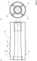
- Figure 3 shows a dowel 22 according to the invention in a first embodiment, as shown for example in Figure 1 can be used.
- Figure 3a shows the dowel 22 in a longitudinal section
- Figure 3b shows a top view of the Figure 3a second end face of the dowel 22 arranged on the left.
- the dowel 22 has a hollow cylindrical basic shape.
- the inner surface of the dowel 22 has the conical region 24 at its end shown on the left.
- the conical region 24 is designed in such a way that it tapers towards the end of the component, i.e. towards the second end face 17 shown in the figure.
- a thread 32 is arranged on the side of the recess 12 opposite the cone 24.
- the receiving mandrel 40 and in particular the bolt 42 of the receiving mandrel 40 can be screwed to the dowel 22 via the thread 32.
- the outer surface 23 of the dowel is essentially cylindrical and has three radial projections 28, 28', 28" in the region of the conical inner surface 24.
- the radial projections 28, 28 ⁇ , 28" are formed as circumferential rings integral with the dowel 22.
- the dowel 22 has longitudinal slots 30, 30', 30", 30′′′ in the area of the conical inner surface 24, which Figure 3b are shown and extend radially over the entire dowel 22.
- the individual longitudinal slots 30, 30', 30", 30′′′ are each arranged offset by 90° from one another.
- the conical inner surface 24 has a cone angle which is designed in such a way that it is a self-locking cone.
- the cone 26 is driven into the conical area 24 of the dowel 22. This is done by applying a predefined force. For this purpose, for example, a screw can be screwed into the thread 32 under a predefined torque.
- a predefined force for this purpose, for example, a screw can be screwed into the thread 32 under a predefined torque.
- the brass dowel 22 expands and in particular the radial projections 28, 28', 28" deform plastically.
- the plastic deformation is facilitated by the four longitudinal slots 30, 30', 30", 30′′′ and an improved pressing of the ring elements is ensured.
- the plastic deformation of the dowel 22 securely fixes the expansion element 20 in the sonotrode body 10.
- the plastic deformation is designed in such a way that the compressive residual stresses of the brass dowel 22 are maximum without leading to failure of the component.
- the sonotrode body 10 is usually made of a titanium alloy. Due to The material of the dowel 22 is softer than that of the sonotrode body 10, meaning that it can absorb the compressive stresses. In addition, the dimensioning of the residual compressive stresses to be introduced must ensure that no friction occurs between the dowel 22 and the sonotrode body 10 due to the induced vibrations, which would lead to wear.
- the third radial projection 28" is arranged in the node surface K 1/4 . No longitudinal vibration occurs in the node surface K 1/4 , but at most minimal transverse contractions of the central recess 12 can occur. However, these can be absorbed and compensated by the plastic deformation of the dowel 22.
- the first and second radial projection 28, 28' are located outside the node surface K 1/4 and thus a longitudinal vibration of the sonotrode body 10 occurs in the area of these projections.
- the plastic deformation of the dowel 22 ensures that no friction occurs between the dowel 22 and the sonotrode body 10. By forming the dowel 22 from a softer material than the sonotrode body 10, it can compensate for the minimal longitudinal vibrations in this area without friction between the projections 28, 28' and the sonotrode body 10. occurs.
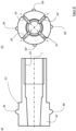
- FIG. 4 An alternative embodiment of the anchor 22 is shown in Figure 4 shown.
- Figure 4a shows a cross section and Figure 4b shows a top view of the Figure 4a left-hand side of the dowel 22.
- the conical inner surface 24 does not decrease towards the left side but widens towards the left or narrows starting from the left end face towards the thread 32.
- the cone 26 is not driven in from the direction of the first end face 15 but from the direction of the second end face 17, i.e. the fastening area 16.
- a further thread 32' is arranged in order to drive or press in the cone 26 with a screw. This enables simple and repeatable pressing of the dowel 22 under predefined forces.
- FIG 5 shows a second embodiment of a round sonotrode 1 according to the invention with a mandrel 40.
- the sonotrode body 10 has, in comparison to the one in Figure 1 shown sonotrode body 10 has a bulge in the central recess 12.
- the bulge is designed as a circumferential groove 18.
- the circumferential groove 18 has a convex outwardly curved cross-section.
- the dowel 22 has a radially outwardly extending, circumferential projection 34.
- the projection 34 has an outwardly convex cross-section which is designed essentially congruent to the cross-section of the groove 18.
- Figure 6 shows a dowel 22 according to the invention in a third embodiment, as shown for example in Figure 5 can be used.
- Figure 6a shows the dowel 22 in a longitudinal section
- Figure 6b shows a top view of the Figure 6a second end face of the dowel 22 arranged on the left.
- the projection 34 extending radially away from the cylindrical region of the outer surface 23 of the dowel 22 is designed as a circumferential projection which is interrupted by the longitudinal slots 30-30′′′.
- the dowel 22 When installing the dowel 22, the dowel 22 is first inserted into the recess 12 until the projection 34 snaps into the groove 18. The cone 26 is then inserted and the dowel 22 is spread open. When inserting the cone 26, it may be necessary to elastically deform the individual sections between the longitudinal slots 30-30′′′ radially inwards so that the projection 19 can be inserted into the recess. When spreading, the outer surface 23 and in particular the projection 34 are plastically deformed.
- Figure 7 shows a third embodiment of a round sonotrode 1 according to the invention with a mandrel 40.
- the sonotrode body 10 has, in comparison to the one in Figure 5
- the sonotrode body shown does not have a bulge in the form of a radial groove 18, but rather four or two continuous radial bores 19, so that the sonotrode body 10 contains four bulges.
- the bores 19 are offset from one another by an angle of 90°.
- the dowel 22 has four projections 36-36′′′, which extend outwards in a substantially hemispherical manner.
- Figure 8 shows a dowel 22 according to the invention in a fourth embodiment, as shown for example in Figure 7 can be used.
- Figure 8a shows the dowel 22 in a longitudinal section
- Figure 8b shows a top view of the Figure 8a second front side of the dowel 22 arranged on the left.
- the projections 36-36′′′ extending radially away from the cylindrical area of the outer surface 23 of the dowel 22 are offset by an angle of 90° to one another and are arranged centrally between two longitudinal slots 30-30′′′.
- it may also have to be rotated about its longitudinal axis so that the projections 36-36′′′ are aligned with the holes 19 and engage in them.
Landscapes
- Engineering & Computer Science (AREA)
- Mechanical Engineering (AREA)
- Pressure Welding/Diffusion-Bonding (AREA)
Priority Applications (1)
| Application Number | Priority Date | Filing Date | Title |
|---|---|---|---|
| EP23169585.9A EP4454868A1 (fr) | 2023-04-24 | 2023-04-24 | Sonotrode ronde avec logement de pièce serré intérieurement |
Applications Claiming Priority (1)
| Application Number | Priority Date | Filing Date | Title |
|---|---|---|---|
| EP23169585.9A EP4454868A1 (fr) | 2023-04-24 | 2023-04-24 | Sonotrode ronde avec logement de pièce serré intérieurement |
Publications (1)
| Publication Number | Publication Date |
|---|---|
| EP4454868A1 true EP4454868A1 (fr) | 2024-10-30 |
Family
ID=86185133
Family Applications (1)
| Application Number | Title | Priority Date | Filing Date |
|---|---|---|---|
| EP23169585.9A Pending EP4454868A1 (fr) | 2023-04-24 | 2023-04-24 | Sonotrode ronde avec logement de pièce serré intérieurement |
Country Status (1)
| Country | Link |
|---|---|
| EP (1) | EP4454868A1 (fr) |
Citations (6)
| Publication number | Priority date | Publication date | Assignee | Title |
|---|---|---|---|---|
| US4029911A (en) * | 1975-04-29 | 1977-06-14 | U.S. Philips Corporation | Electro-acoustic transducer and method of manufacturing such a transducer |
| DE102013202766A1 (de) | 2013-02-20 | 2014-08-21 | Ms Spaichingen Gmbh | Rundsonotrode |
| DE102014212313A1 (de) | 2014-06-26 | 2015-12-31 | Telsonic Holding Ag | Torsionssonotrode, Vorrichtung und Verfahren zum Schweißen mittels Ultraschall |
| DE102014111661A1 (de) | 2014-08-14 | 2016-02-18 | Herrmann Ultraschalltechnik Gmbh & Co. Kg | Schwingungselement mit entkoppeltem Bauteil |
| DE102015103799A1 (de) | 2015-03-16 | 2016-09-22 | Rehau Ag + Co | Sonotrode für eine Ultraschall-Schweißanlage sowie Verfahren zur Verschweißung eines Anschlusselementes mit einem Bauteil |
| DE202017104190U1 (de) | 2017-07-13 | 2018-10-16 | PP-Tech GmbH | Ultraschallbearbeitungseinrichtung und radial-resonante Ultraschallsonotrode |
-
2023
- 2023-04-24 EP EP23169585.9A patent/EP4454868A1/fr active Pending
Patent Citations (6)
| Publication number | Priority date | Publication date | Assignee | Title |
|---|---|---|---|---|
| US4029911A (en) * | 1975-04-29 | 1977-06-14 | U.S. Philips Corporation | Electro-acoustic transducer and method of manufacturing such a transducer |
| DE102013202766A1 (de) | 2013-02-20 | 2014-08-21 | Ms Spaichingen Gmbh | Rundsonotrode |
| DE102014212313A1 (de) | 2014-06-26 | 2015-12-31 | Telsonic Holding Ag | Torsionssonotrode, Vorrichtung und Verfahren zum Schweißen mittels Ultraschall |
| DE102014111661A1 (de) | 2014-08-14 | 2016-02-18 | Herrmann Ultraschalltechnik Gmbh & Co. Kg | Schwingungselement mit entkoppeltem Bauteil |
| DE102015103799A1 (de) | 2015-03-16 | 2016-09-22 | Rehau Ag + Co | Sonotrode für eine Ultraschall-Schweißanlage sowie Verfahren zur Verschweißung eines Anschlusselementes mit einem Bauteil |
| DE202017104190U1 (de) | 2017-07-13 | 2018-10-16 | PP-Tech GmbH | Ultraschallbearbeitungseinrichtung und radial-resonante Ultraschallsonotrode |
Similar Documents
| Publication | Publication Date | Title |
|---|---|---|
| EP2486288B1 (fr) | Liaison entre deux éléments en plastique renforcé et son procédé de fabrication | |
| EP3271136B1 (fr) | Sonotrode pour système de soudage par ultrasons et procédé de soudage d'un élément de raccordement à un composant | |
| EP2288450A1 (fr) | Unité émettrice d'ultrasons avec support | |
| DE102016105354A1 (de) | Spanabhebendes Werkzeug | |
| DE102006019405A1 (de) | Werkzeug zur Kaltexpansion von Löchern | |
| WO2017000998A1 (fr) | Dispositif pour souder des pièces au moyen d'ultrasons par des oscillations de torsion | |
| DE2912019A1 (de) | Befestiger | |
| DE69909359T2 (de) | Distanzhülse | |
| EP1250210A1 (fr) | Procede pour assembler deux pieces par soudage par friction, et element de machine realise selon ce procede | |
| EP4454868A1 (fr) | Sonotrode ronde avec logement de pièce serré intérieurement | |
| EP1122102B1 (fr) | Jambe de suspension | |
| DE10325431A1 (de) | Verbindungsanordnung zweier Bauteile mit einem Blindniet und Verfahren zum Vernieten zweier Bauteile | |
| EP1660769B1 (fr) | Piston en plusieurs parties destine a un moteur a combustion interne | |
| DE2829253A1 (de) | Vorrichtung zur verformung einer elastomerschicht fuer einen drehschwingungsdaempfer | |
| DE102012220033A1 (de) | Funktionselement zum Einpressen in ein Blechteil und Zusammenbauteil bestehend aus dem Funktionselement und einem Blechteil | |
| DE202017104190U1 (de) | Ultraschallbearbeitungseinrichtung und radial-resonante Ultraschallsonotrode | |
| EP1650467B1 (fr) | Amortisseur de vibrations | |
| EP0926415B1 (fr) | Raccord de tuyaux | |
| EP3600849B1 (fr) | Élément de montage à relier à une pièce | |
| DE202006000285U1 (de) | Elastomer-Metall-Gelenklager, insbesondere als Zentralgelenklager eines Dreieckslenkers zur Verbindung eines Achskörpers mit einem Fahrzeugaufbau | |
| DE19734539C2 (de) | Bauteilverbindung | |
| DE102019124519A1 (de) | Hydraulische Dehnspanneinrichtung | |
| DE102018102068A1 (de) | Dämpfungsvorrichtung mit Ganzmetallkissen | |
| DE102007019699A1 (de) | Schraubverbindung | |
| DE19524926B4 (de) | Elastische Bolzenkupplung |
Legal Events
| Date | Code | Title | Description |
|---|---|---|---|
| PUAI | Public reference made under article 153(3) epc to a published international application that has entered the european phase |
Free format text: ORIGINAL CODE: 0009012 |
|
| STAA | Information on the status of an ep patent application or granted ep patent |
Free format text: STATUS: THE APPLICATION HAS BEEN PUBLISHED |
|
| AK | Designated contracting states |
Kind code of ref document: A1 Designated state(s): AL AT BE BG CH CY CZ DE DK EE ES FI FR GB GR HR HU IE IS IT LI LT LU LV MC ME MK MT NL NO PL PT RO RS SE SI SK SM TR |
|
| STAA | Information on the status of an ep patent application or granted ep patent |
Free format text: STATUS: REQUEST FOR EXAMINATION WAS MADE |
|
| 17P | Request for examination filed |
Effective date: 20250428 |
|
| RIC1 | Information provided on ipc code assigned before grant |
Ipc: B29C 65/78 20060101AFI20260224BHEP Ipc: B29C 65/08 20060101ALI20260224BHEP Ipc: B29C 65/00 20060101ALI20260224BHEP Ipc: B29L 31/30 20060101ALN20260224BHEP Ipc: B29L 31/00 20060101ALN20260224BHEP |
|
| GRAP | Despatch of communication of intention to grant a patent |
Free format text: ORIGINAL CODE: EPIDOSNIGR1 |
|
| STAA | Information on the status of an ep patent application or granted ep patent |
Free format text: STATUS: GRANT OF PATENT IS INTENDED |
|
| RIC1 | Information provided on ipc code assigned before grant |
Ipc: B29C 65/78 20060101AFI20260306BHEP Ipc: B29C 65/08 20060101ALI20260306BHEP Ipc: B29L 31/30 20060101ALN20260306BHEP Ipc: B29L 31/00 20060101ALN20260306BHEP |
|
| RIC1 | Information provided on ipc code assigned before grant |
Ipc: B29C 65/78 20060101AFI20260317BHEP Ipc: B29C 65/08 20060101ALI20260317BHEP Ipc: B29L 31/30 20060101ALN20260317BHEP Ipc: B29L 31/00 20060101ALN20260317BHEP |