EP4454961A2 - Essieu de véhicule avec moteurs d'entraînement électriques et frein électrohydraulique et autres modules tels que boîte de vitesses, torque vectoring et frein de stationnement - Google Patents
Essieu de véhicule avec moteurs d'entraînement électriques et frein électrohydraulique et autres modules tels que boîte de vitesses, torque vectoring et frein de stationnement Download PDFInfo
- Publication number
- EP4454961A2 EP4454961A2 EP24188961.7A EP24188961A EP4454961A2 EP 4454961 A2 EP4454961 A2 EP 4454961A2 EP 24188961 A EP24188961 A EP 24188961A EP 4454961 A2 EP4454961 A2 EP 4454961A2
- Authority
- EP
- European Patent Office
- Prior art keywords
- ecu
- pressure supply
- vehicle axle
- pressure
- brake
- Prior art date
- Legal status (The legal status is an assumption and is not a legal conclusion. Google has not performed a legal analysis and makes no representation as to the accuracy of the status listed.)
- Pending
Links
Images







Classifications
-
- B—PERFORMING OPERATIONS; TRANSPORTING
- B60—VEHICLES IN GENERAL
- B60T—VEHICLE BRAKE CONTROL SYSTEMS OR PARTS THEREOF; BRAKE CONTROL SYSTEMS OR PARTS THEREOF, IN GENERAL; ARRANGEMENT OF BRAKING ELEMENTS ON VEHICLES IN GENERAL; PORTABLE DEVICES FOR PREVENTING UNWANTED MOVEMENT OF VEHICLES; VEHICLE MODIFICATIONS TO FACILITATE COOLING OF BRAKES
- B60T13/00—Transmitting braking action from initiating means to ultimate brake actuator with power assistance or drive; Brake systems incorporating such transmitting means, e.g. air-pressure brake systems
- B60T13/10—Transmitting braking action from initiating means to ultimate brake actuator with power assistance or drive; Brake systems incorporating such transmitting means, e.g. air-pressure brake systems with fluid assistance, drive, or release
- B60T13/58—Combined or convertible systems
- B60T13/588—Combined or convertible systems both fluid and mechanical assistance or drive
-
- B—PERFORMING OPERATIONS; TRANSPORTING
- B60—VEHICLES IN GENERAL
- B60T—VEHICLE BRAKE CONTROL SYSTEMS OR PARTS THEREOF; BRAKE CONTROL SYSTEMS OR PARTS THEREOF, IN GENERAL; ARRANGEMENT OF BRAKING ELEMENTS ON VEHICLES IN GENERAL; PORTABLE DEVICES FOR PREVENTING UNWANTED MOVEMENT OF VEHICLES; VEHICLE MODIFICATIONS TO FACILITATE COOLING OF BRAKES
- B60T13/00—Transmitting braking action from initiating means to ultimate brake actuator with power assistance or drive; Brake systems incorporating such transmitting means, e.g. air-pressure brake systems
-
- B—PERFORMING OPERATIONS; TRANSPORTING
- B60—VEHICLES IN GENERAL
- B60T—VEHICLE BRAKE CONTROL SYSTEMS OR PARTS THEREOF; BRAKE CONTROL SYSTEMS OR PARTS THEREOF, IN GENERAL; ARRANGEMENT OF BRAKING ELEMENTS ON VEHICLES IN GENERAL; PORTABLE DEVICES FOR PREVENTING UNWANTED MOVEMENT OF VEHICLES; VEHICLE MODIFICATIONS TO FACILITATE COOLING OF BRAKES
- B60T13/00—Transmitting braking action from initiating means to ultimate brake actuator with power assistance or drive; Brake systems incorporating such transmitting means, e.g. air-pressure brake systems
- B60T13/10—Transmitting braking action from initiating means to ultimate brake actuator with power assistance or drive; Brake systems incorporating such transmitting means, e.g. air-pressure brake systems with fluid assistance, drive, or release
- B60T13/66—Electrical control in fluid-pressure brake systems
-
- B—PERFORMING OPERATIONS; TRANSPORTING
- B60—VEHICLES IN GENERAL
- B60T—VEHICLE BRAKE CONTROL SYSTEMS OR PARTS THEREOF; BRAKE CONTROL SYSTEMS OR PARTS THEREOF, IN GENERAL; ARRANGEMENT OF BRAKING ELEMENTS ON VEHICLES IN GENERAL; PORTABLE DEVICES FOR PREVENTING UNWANTED MOVEMENT OF VEHICLES; VEHICLE MODIFICATIONS TO FACILITATE COOLING OF BRAKES
- B60T13/00—Transmitting braking action from initiating means to ultimate brake actuator with power assistance or drive; Brake systems incorporating such transmitting means, e.g. air-pressure brake systems
- B60T13/74—Transmitting braking action from initiating means to ultimate brake actuator with power assistance or drive; Brake systems incorporating such transmitting means, e.g. air-pressure brake systems with electrical assistance or drive
- B60T13/745—Transmitting braking action from initiating means to ultimate brake actuator with power assistance or drive; Brake systems incorporating such transmitting means, e.g. air-pressure brake systems with electrical assistance or drive acting on a hydraulic system, e.g. a master cylinder
-
- B—PERFORMING OPERATIONS; TRANSPORTING
- B60—VEHICLES IN GENERAL
- B60T—VEHICLE BRAKE CONTROL SYSTEMS OR PARTS THEREOF; BRAKE CONTROL SYSTEMS OR PARTS THEREOF, IN GENERAL; ARRANGEMENT OF BRAKING ELEMENTS ON VEHICLES IN GENERAL; PORTABLE DEVICES FOR PREVENTING UNWANTED MOVEMENT OF VEHICLES; VEHICLE MODIFICATIONS TO FACILITATE COOLING OF BRAKES
- B60T8/00—Arrangements for adjusting wheel-braking force to meet varying vehicular or ground-surface conditions, e.g. limiting or varying distribution of braking force
- B60T8/17—Using electrical or electronic regulation means to control braking
- B60T8/1755—Brake regulation specially adapted to control the stability of the vehicle, e.g. taking into account yaw rate or transverse acceleration in a curve
-
- B—PERFORMING OPERATIONS; TRANSPORTING
- B60—VEHICLES IN GENERAL
- B60T—VEHICLE BRAKE CONTROL SYSTEMS OR PARTS THEREOF; BRAKE CONTROL SYSTEMS OR PARTS THEREOF, IN GENERAL; ARRANGEMENT OF BRAKING ELEMENTS ON VEHICLES IN GENERAL; PORTABLE DEVICES FOR PREVENTING UNWANTED MOVEMENT OF VEHICLES; VEHICLE MODIFICATIONS TO FACILITATE COOLING OF BRAKES
- B60T2270/00—Further aspects of brake control systems not otherwise provided for
- B60T2270/40—Failsafe aspects of brake control systems
-
- B—PERFORMING OPERATIONS; TRANSPORTING
- B60—VEHICLES IN GENERAL
- B60T—VEHICLE BRAKE CONTROL SYSTEMS OR PARTS THEREOF; BRAKE CONTROL SYSTEMS OR PARTS THEREOF, IN GENERAL; ARRANGEMENT OF BRAKING ELEMENTS ON VEHICLES IN GENERAL; PORTABLE DEVICES FOR PREVENTING UNWANTED MOVEMENT OF VEHICLES; VEHICLE MODIFICATIONS TO FACILITATE COOLING OF BRAKES
- B60T2270/00—Further aspects of brake control systems not otherwise provided for
- B60T2270/40—Failsafe aspects of brake control systems
- B60T2270/402—Back-up
Definitions
- the present invention relates to a device for an electric axle for electric vehicles, particularly designed for vehicles in increasingly autonomous driving mode
- stage 5 the pedal travel sensor and pedal simulator and their characteristics are no longer relevant.
- the remaining components and subsystems will have 3-fold redundancy, with the "2 out of 3" rule for sensors, control and regulation units (ECU) and partial ECU, or multiple redundancy.
- ECU control and regulation units
- complete redundancy must be provided for the wheel-specific control.
- EMB electromechanical brake
- electromechanical wedge brake electromechanical wedge brake
- the EMB has not been successful in the past due to safety concerns and high costs.
- the high costs are mainly due to the fact that an electric motor and a complex electromechanical mechanism are required for each wheel brake.
- an EMB has a large number of electrical contact points, which are known to be more prone to errors than hydraulic lines.
- braking systems for the FAD and AD stages cannot exclusively have EMB or wedge brakes.
- An EMB is only suitable for the rear axle of a vehicle because the rear axle has a smaller share of the braking force and a failure is not considered as critical as on the front axle.
- a hydraulic braking system with control in the predominantly closed brake circuit via an electrically driven piston-cylinder unit is preferable.
- the pressure is controlled using a non-linear characteristic field, the so-called pressure-volume characteristic curve, in which the relationship between pressure and piston position is evaluated.
- the pressure is used by phase current control of the electric motor, whereby the physical relationship of the proportionality between current and torque and due to a known piston area and fixed gear ratio also Proportionality between current and pressure exists and is used. With these two parameters, the pressure and the pressure change curve can be controlled very precisely.
- WO201614622A2 In addition, a special valve circuit of switching valves is implemented, where the interior of the switching valve is connected to the associated brake circuit via a hydraulic line and the valve seat compensation is connected to the associated wheel brake via a hydraulic line.
- This valve circuit is particularly suitable for the MUX method with only one switching valve per brake circuit, since in the event of a fault the solenoid valve opens due to the pressure in the wheel brake and thus prevents the pressure in the wheel brake from remaining locked in, which leads to unwanted vehicle deceleration.
- Electric motors are an integral part of one or more axles and axle concepts with integrated electric motors are increasingly being offered by various suppliers as part of e-vehicle platforms. This achieves maximum flexibility in vehicle design and vehicles can implement new vehicle interior concepts because the combustion engine is no longer a limiting factor in the length of the vehicle.
- the object of the present invention is to provide a vehicle axle for electric vehicles with an integrated actuator for braking and driving dynamics tasks, thereby meeting the requirements of high availability in fully automated driving (FAD) and autonomous driving (AD) and additionally creating the basis for the integration of further hydraulic actuators, in particular for the steering, transmission actuators and torque vectoring modules.
- FAD fully automated driving
- AD autonomous driving
- the invention is advantageously characterized by the fact that redundancy requirements of fully automated driving (FAD) and autonomous driving (AD) are met and at the same time high synergy effects are used in the interaction of the braking system with electric drive motors of electric vehicles.
- FAD fully automated driving
- AD autonomous driving
- the energy recovery of kinetic energy by the electric motor is not carried out by the braking system as is the case with follow-up brake boosters without a path simulator according to DE 11 2009 005 541 B3 limited, at the same time the electric motor can contribute to braking.
- the vehicle axle according to the invention is advantageously equipped with an actuating unit (BE) with a pedal feel simulator for FAD.
- BE actuating unit
- an actuation unit with appropriate redundancies must be provided for autonomous driving.
- the actuation unit optionally has a hydraulic connection to at least one brake circuit or is used as a pure pedal feel simulator without connection to the hydraulics of the brake system, with the actuation force then being transmitted purely electrically.
- An electric brake pedal e-brake pedal
- the aim is to make the actuation unit extremely short so that the length advantages of e-axle concepts can be exploited to the maximum.
- no actuation unit is provided, with a central control unit (M-ECU) taking over the communication with the actuating units.
- M-ECU central control unit
- This design provides at least two-fold redundancy, at least for the pressure supply and its control, and several hydraulic actuators can be controlled very precisely with only one or fewer, in particular two, pressure supply devices. This makes it possible to create a very cost-effective and reliable solution for several hydraulic actuators (brake, gear actuator, steering).
- the very precise pressure control based on the basic patents DE102005055751B4 and DE102005018649B4
- the PPC process can achieve performance comparable to that of a purely electromechanical solution (e.g. electric power steering, electromechanical brake) at significantly lower costs.
- the vehicle axle is preferably designed in such a way that all hydraulic components or actuators (brakes, steering, transmission actuators, clutches, etc.) with slave electronics and hydraulic control units HCU with valves and pressure sensors are positioned on the vehicle axle or are sensibly integrated into the units and the control of all modules is carried out via a higher-level control unit (M-ECU) that is not located on the vehicle axle.
- M-ECU higher-level control unit
- This also makes it possible to have actuating units such as the brake pedal on the bulkhead to the vehicle interior. The actuating units are not required for vehicles of level AD.
- the control signals to the various components or actuators of the vehicle axle can preferably be transmitted redundantly and a fast BUS system such as Flexray ® is preferably used for fast data transmission without time delay. Diagnostic processes as well as engine and pressure control are components of the slave ECU modules of the various components.
- each, electronic control and regulating unit controls separate windings of the or an electric motor drive. This advantageously ensures that if a winding system fails, the drive motor can still be operated at at least half the maximum torque.
- the previously described embodiments can also be made safer if either one, in particular redundant, valve arrangement is advantageously assigned to each pressure supply device or a redundant valve arrangement is assigned to two pressure supply devices.
- the invention understands a redundant valve arrangement to be designed in such a way that if one or both control and regulating units of the pressure supply device fail, the solenoid valves of the pressure supply or the units of the vehicle axle can still be operated safely.
- actuating device in particular in the form of a Brake pedal
- a brake pressure can be built up with the actuating device in at least one brake circuit via a hydraulic connection.
- a simple master brake cylinder or a tandem master cylinder and the mandatory pedal feel simulator can be provided.
- the braking systems described above are advantageously regulated in normal operation with a closed brake circuit, i.e. in normal operation there is no pressure reduction via solenoid valves in the reservoir and/or the pressure in the wheel brakes of the respective brake circuit is regulated or set using the PPC and/or multiplex method.
- the switching valves should be connected to the wheel brakes in such a way that they open automatically when pressure is applied by the wheel brake. This advantageously ensures that the brake pressure in the wheel brakes can be reduced in every case and that there is no undesired braking or locking of the wheels.
- At least one wheel brake is a hydraulically assisted electromechanical brake (H-EMB), an electric parking brake (EPB) or an electromechanical brake (EMB).
- H-EMB hydraulically assisted electromechanical brake
- EPB electric parking brake
- EMB electromechanical brake
- an electric motor of an additional electric parking brake or an electromechanical brake can act to brake the wheel. This measure creates further redundancy.
- a hydraulically assisted electromechanical brake it can advantageously be used to build up braking force both hydraulically and electromechanically.
- M-ECU higher-level control unit
- M-ECU higher-level control unit
- It sends control signals to the various actuators. It can control the pressure supply devices, valves, electric drive motors and/or EMB or H-EMB during braking and/or ABS control operation. and/or to diagnose the braking system and can also usefully control other driving dynamics functions in addition to the brakes, e.g. steering, damping, roll stabilization.
- At least one electric drive or traction motor is provided for at least one axle or wheel of the vehicle, this can advantageously be used to brake an axle or wheel. This provides further redundancy. In this way, in normal operation or in the event of failure of a component of the braking system, e.g. a pressure supply device, a (supporting) braking force can also be generated by means of the traction motor(s).
- a component of the braking system e.g. a pressure supply device
- a faster increase in braking force with a shorter time to lock (TTL) can advantageously be achieved in normal operation or in the event of failure of one or more components of the braking system.
- At least one isolating valve can advantageously be connected upstream of each pressure supply device at the outlet of the pressure supply, wherein the respective pressure supply device can be separated from the respective brake circuit by closing the isolating valve, in particular in the event of its failure.
- At least one control and regulating device of a pressure supply and valve arrangement can have a separate voltage supply and in particular signal transmission, in particular all modules of a pressure supply device can be supplied by at least two on-board networks and/or have redundant signal transmissions.
- Two on-board networks means that either different voltage levels and/or voltage sources are used to supply the components.
- either the pressure control in a brake circuit is carried out using at least one pressure sensor and/or by measuring the current of the motor current of the drive and controlling the piston of the pressure supply device, which can be further refined in terms of pressure control quality by taking the temperature of the drive into account.
- connection module with switching valves is arranged between the axles so that either the brake circuits of the front axle and rear axle can be connected to one another, separated from one another and/or one or both brake circuits can be connected to the reservoir, particularly if no actuating device is provided by which pressure can be reduced in the reservoir.
- the normally open solenoid valves used to connect the brake circuits to the reservoir are advantageously used.
- normally closed solenoid valves or hydraulic fluid transfer pistons that can be locked in position should preferably be used in the connection module.
- connection module can either have, for example, several solenoid valves, via which a hydraulic connection can be established between a brake circuit and the reservoir or between the two brake circuits.
- connection module it is also possible for the connection module to be formed by a piston-cylinder unit, the piston of which separates a first and a second pressure chamber from one another, the first pressure chamber being connected to one first brake circuit and the second pressure chamber being connected to the other second brake circuit, and the piston being lockable by means of a blocking device. In the locked state, there would then be virtually no hydraulic connection between the brake circuits, since a volume shift is prevented.
- the piston-cylinder units of the vehicle axle have redundant seals and hydraulic diagnostic lines and redundant regulation and control units are also provided, and that the drives of the pressure supply devices have 2x3 phases, and that the motor phase current i phase , the motor angle ⁇ , and in particular the temperature T, are measured by means of sensors and taken into account in the pressure regulation, and that a redundant supply is provided via two on-board networks or voltage levels, and that redundant signal transmission is provided.
- the provision of all these measures advantageously results in a very safe system that is suitable for AD levels 3-5.
- a storage container can advantageously be used with the vehicle axles described above, which has several separate chambers, wherein one chamber of the storage container is hydraulically connected or connectable to at least one pressure supply device and/or another chamber is hydraulically connected or connectable to the connection module. This advantageously results in further switching options using the valves used, which contribute to the further safety of the vehicle axle.
- the above-described braking systems of the vehicle axles can advantageously be operated in such a way that the wheels are decelerated at least on an axle-by-axle basis, preferably individually by wheel, by means of the pressure supply device(s), the electric drive motor(s) and the hydraulically assisted electromechanical brake (H-EMB) or the electromechanical brake (EMB).
- Torque vectoring can also be carried out by means of the pressure supply device(s), the electric drive motor(s) (TM) and the hydraulically assisted electromechanical brake (H-EMB) or the electromechanical brake (EMB).
- the piston position and the pressure volume characteristic can also be used for pressure control, and the change in the pressure volume characteristic in the event of air inclusion, for example, can be adjusted using the pressure sensor or the H-EMB.
- the combined use of both of the methods described above results in highly precise pressure control, which is also possible without a pressure sensor.
- This method provides additional redundancy in the event of pressure sensor failure or can also be used to simplify the system with low redundancy requirements (e.g. system with only one or no pressure sensor).
- the braking system of the vehicle axle according to the invention can also be used for steering/torque vectoring and for the actuation of transmissions, in particular clutches, wherein the wheel-individual control options can be used with the at least one pressure supply and the hydraulically assisted electromechanical brake(s) H-EMB, electric parking brake(s) EPB and/or electromechanical brake(s) EMB and/or drive motors or the steering EPS.
- Table 1 according to Figure 7 are for the vehicle axle according to the invention or various driving dynamics control functions, such as electric brake booster e-BKV, ABS operation, steering/torque vectoring, Stability control/ESP, energy recovery by electric motor and parking brake EPB, transmission lock GS, which can be represented by the components pressure supply on axle 1 (DV1-A1 and DV2-A1) or pressure supply on axle 2 (DV-A2), drive motor TM1, TM2, electro-hydraulic steering EPS and hydraulically assisted H-EMB or parking brake EPB, are explained.
- the primary function and the secondary function/redundancy are identified. This makes it clear that the most important driving dynamics functions of an axle are at least 2-fold redundant.
- the pressure control can even be considered 3-fold redundant when designed as a 2x3 phase motor and connection module between the front axle and rear axle.
- the PPC method see above for DE102005055751B4 and DE102005018649B4 , can be refined by temperature measurement and can be used for brakes, steering and clutches, especially in the event of a pressure sensor failure, providing further redundancy in operation.
- the inventive e-axle system with integrated braking system is therefore suitable for all levels of autonomous driving up to level 5 (AD).
- a pressure supply device can also be driven by a rotary pump, which can in particular be a gear pump. It can then have a motor housing with an electric motor drive arranged therein, which drives the gear pump.
- the drive has a stator and a rotor. An inner gear of the gear pump is moved via the rotor of the drive.
- the drive is designed as a dry rotor by means of at least one seal which is arranged between the rotor and the inner gear, or has a dry-running rotor, i.e. the rotor of the drive is not flowed around by the medium pumped by the gear pump and/or is not surrounded by the medium. By designing it as a dry rotor, the rotor rotates without great friction and flow resistance, which means that higher speeds and better efficiency can be achieved.
- a particularly compact and simple pressure supply device is obtained if the motor housing has a side wall on which the gear pump is arranged, in particular if this has a recess in which the gear pump is at least partially or completely located.
- the side wall of the motor housing can be penetrated by a shaft that is connected to the rotor in a rotationally fixed manner, with the gear either being connected to the shaft in a rotationally fixed manner or being coupled to the shaft via an intermediate gear and/or a clutch.
- the drive with its housing rests against a hydraulic housing with at least one valve and/or hydraulic lines or channels arranged therein or forms a unit with it.
- the side wall of the drive housing can rest against or abut the side wall of the hydraulic housing, in particular be fastened to it, wherein the, in particular pot-shaped, recess at least partially or completely accommodates the gear pump and is open towards the hydraulic housing.
- the gear pump can either lie completely in the recess in the wall of the drive housing, completely in a recess in the hydraulic housing or both in a recess in the side wall of the drive housing and in a recess in the side wall of the hydraulic housing. In the latter case, the openings of the two recesses then face each other. Additional seals can be provided in order to seal the two housings from one another and from the outside.
- the above-described recess in the side wall of the drive housing is advantageously open to the outside and, if a hydraulic housing is present, to the latter.
- the recess itself can advantageously be pot-shaped. It can also have a cylindrical section with a circular cross-section in which the gear pump and its gears are located.
- the side wall of the drive housing can also advantageously be designed as a flange with which the drive can be attached to another part or unit can be attached.
- the gear pump used in the pressure supply device according to the invention can be an internal gear pump with a sickle, an external gear pump or a gear ring pump.
- the gear pump can also advantageously be arranged axially next to the stator and/or the rotor of the drive, its structure and size are not disadvantageously limited by the gear pump.
- the gear pump is then also not dependent on the dimensions of the stator and the rotor in terms of its size and structure.
- the drive housing can be made up of at least two parts, with the side wall being part of or forming a first housing part.
- the second housing part can be pot-shaped, for example, and can accommodate the stator and the rotor of the drive.
- the rotor is connected to the gear by means of a drive shaft directly or via a gear and/or a clutch.
- the gear can be connected to the drive shaft in a rotationally fixed manner either by means of a force-fit connection or by means of a form-fit connection, which is formed in particular by means of a pin or serration.
- the inner gear is arranged eccentrically on a part connected to the drive shaft, in particular in the form of a disk or a cam disk.
- the gear pump of the pressure supply device is designed as an internal gear pump or as a gear ring pump
- an external internal gear ring is also required in addition to the internal gear.
- the internal gear ring is rotated about its axis of rotation by means of the internal gear driven by the drive shaft, with the internal gear wheel being arranged eccentrically to the internal gear ring.
- the internal gear ring rotates in an external ring or cylinder that surrounds it.
- a sickle must be provided, which must be arranged in the space between the internal gear ring and the inner gear wheel resulting from the eccentricity.
- the internal gear ring In contrast to the internal gear pump, the internal gear ring is fixed in the gerotor pump, whereby the inner gear rolls in the internal gear ring due to its eccentric bearing on the disk rotated by the drive shaft. A sickle as in the internal gear pump is not required.
- the drive shaft can extend into the hydraulic housing, in particular to the side opposite the drive.
- a target for a sensor can be arranged on the drive shaft, with the sensor being arranged in the control and regulating unit (ECU). Additional seals can prevent the pumped medium from entering the control and regulating unit. It is also possible for the drive shaft to extend all the way through the hydraulic housing and end in the adjoining housing, e.g. a control and regulating unit.
- the gear pump as an internal gear pump can be designed in different ways.
- the inner gear, the inner gear ring, the sickle and the outer ring can be arranged between two disks, whereby after appropriate centering and adjustment of the parts to each other, the disks are connected to the outer ring in a material-locking manner.
- the material-locking connection can extend all the way around the circumference, resulting in a stable and compact design, with in which the individual moving parts have only small clearances and gaps between each other, thus achieving good efficiency and high pressure.
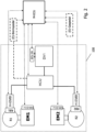
- the Figure 1 shows a first possible embodiment of the vehicle axle 100 according to the invention with the wheels R1 and R2, wherein each wheel is braked by means of a conventional wheel brake RB1, RB2 and additionally has a parking brake EPB.
- the vehicle axle 100 also has an electric motor EM with control EM-ECU for driving the axle, as well as an electro-hydraulic power steering EHPS.
- the vehicle axle in a first expansion variant has a pressure supply device DV1, which together with the valve arrangement HCU carries out the pressure control in the wheel brakes RB1 and RB2 in the multiplex method and/or PPC method.
- the pressure supply device DV1 is controlled by a control and regulating unit ECU DV1, wherein this controls the electric drive motor of the Pressure supply device DV1 is controlled. If one of the two phase or winding systems fails, the drive motor can continue to operate with reduced power so that there is no total failure of the pressure supply device DV1. If further redundancy is to be created, this can be done by providing a second pressure supply device DV2, which is also controlled by a control and regulating device ECU DV2 and can also have two winding or phase systems to increase reliability.
- the pressure supply or regulation of the electro-hydraulic power steering EHPS is also carried out by the pressure supply device, whereby this takes place separately from the pressure regulation in the wheel brakes by means of the valve arrangement HCU. If assisted steering is also required at the same time as braking, the wheel brakes RB1 and RB2 can be supplied together with the steering in multiplex operation. If two pressure supply devices DV1 and DV2 are provided, the steering also has two redundant pressure supply devices.
- the dashed line marked with 100 forms the system boundary of the vehicle axle according to the invention.
- the valve arrangement can be as in Figure 1a shown, with each wheel brake RB1, RB2 being assigned a switching valve SV1, SV2.
- the switching valve SV1, SV2 When the switching valve SV1, SV2 is open, the pressure in the respective wheel brake RB1, RB2 can be regulated by means of the pressure supply device V1, with the pressure in the respective wheel brake RB1, RB2 being enclosed or frozen when the switching valve Sv1, SV2 is closed. It is optionally possible to provide an outlet valve for at least one wheel brake so that the pressure in this wheel brake can be reduced via the outlet valve.
- the associated switching valve is closed, the pressure in the other wheel brake can then be built up at the same time using the pressure supply device.
- a braking torque can be generated alternatively or additionally using the parking brakes EPB and/or the electric drive EM.
- FIG. 1a When providing a not shown actuating device BE, as shown in Figure 1a is shown schematically, which has a piston-cylinder unit whose piston can be adjusted using the brake pedal of the actuating device BE, a braking pressure can be built up in the wheel brakes RB1, RB2 in an emergency.
- a separating valve TV1 must be connected upstream of the pressure supply device, which is closed when de-energized, whereby the pressure supply device DV1 is separated from the wheel brakes RB1, RB2 and the actuating device BE.
- the pressure control in the wheel brakes is carried out via the pressure sensor p/U and additionally via the PPC method with displacement control of the piston of the pressure supply device DV1, and additionally or in the event of failure of the pressure sensor via the motor current and pressure volume characteristic of the system.
- the pressure control in the steering EHPS is carried out via the volume control by displacement control of the piston of the piston-cylinder unit of the steering EHPS, for which the steering has at least one, advantageously an additional preferably redundant, displacement sensor x/U, see Figure 1a
- the angle sensor ⁇ /U of the electric motor of the pressure supply device can also be used, which is also designed redundantly.
- All components of the vehicle axle are controlled by the higher-level control and regulation unit M-ECU.
- an electric brake pedal for brake-by-wire and an electric accelerator pedal E-accelerator pedal can be provided instead of an actuating device BE.
- the Figure 1a shows a hydraulic diagram of the vehicle axle according to Figure 1 with only one pressure supply device DV1, which has two control and regulating units DV-ECU1 and DV-ECU2, each control and regulating unit controlling a 3-winding system of the drive, so that even if a control and regulating unit or a 3-winding system fails, the pressure supply can be operated with reduced dynamics and reduced maximum pressure.
- the EHPS steering system has an inlet valve EVS1, EVS2, EVS3, EVS4 for each pressure chamber, whereby by opening the switching valves the piston for steering support is adjustable.
- the EHPS control follows in such a way that to move the piston in the direction of wheel R2, the EVS1 valve and the EVS4 valve are opened, while EVS2 and EVS4 are closed.
- the EVS2 and EVS3 valves are opened and EVS1, EVS4 valves are opened.
- the steering can be controlled using an emergency control procedure in such a way that the leakage rates are determined via the piston of the pressure supply device and the valves are controlled intelligently so that steering in both directions is possible despite the leak.
- steering modules are provided on several axles.
- the Figure 1b shows a vehicle axis according to Figure 1a Another embodiment, in which a purely electro-hydraulic brake is provided and the pressure supply device is only connected to the steering module.
- the EHPS steering system only has one switching valve EVS1.
- the Figure 1c shows a further possible embodiment of the vehicle axle according to the invention, in which two pressure supply devices DV1 and DV2 are provided, each of which has two control and regulating units DV-ECU1 and DV-ECU2.
- Each control and regulating unit DV-ECU1 and DV-ECU2 controls its own phase or winding system of the motor M1, M2, so that the control and regulating units are designed redundantly.
- further redundancies can be provided if the voltage supply and/or the signal lines for the control and regulating units DV-ECU1 and DV-ECU2 are designed redundantly, ie a supply from two on-board networks and/or two voltage levels BN1, BN2 is provided or the data lines DS1, DS2 are designed redundantly.
- the pressure supply device DV1 is intended for pressure control in the wheel brakes RB1 and RB2.
- the pressure supply device DV2 is intended for pressure control or pressure supply to the steering EHPS.
- the two hydraulic systems are separated from each other so that a fault in one system cannot affect the other.
- the functioning of the steering is in Figure 1a described.
- the Figure 2 shows a schematic diagram of a second possible embodiment of the vehicle axle 100.
- the wheel brakes RB1 and RB2 of the axle 100 are formed by hydraulically supported electromechanical brakes H-EMB, with which a braking force can be built up in normal operation not only by means of the pressure supply device DV1 but also by means of the vehicle's own electric drive. This can be used as a support or in the event of a total failure.
- a deceleration of the vehicle wheels R1 and R2 can be generated as a support or on its own using the traction drives EM1 and EM2.
- the control and regulation unit ECU DV can be designed identically to that in the previously described embodiments. This means that it can be designed redundantly.
- a second pressure supply device can also be provided as a replacement for the pressure supply device DV1 in an emergency.
- the components are controlled by the higher-level control and regulation unit M-ECU, whereby, as already described, an actuation unit BE can be provided optionally.
- This can either have a purely electronic brake pedal (E-brake pedal) or has a piston-cylinder unit, the piston of which can be adjusted in an emergency using the brake pedal to build up pressure in the wheel brakes, so that emergency braking is still possible.
- This braking force generated by the foot can be supported by the traction motors EM1, EM2 and the motors of the hydraulically assisted brakes H-EMB.
- a steering EHPS and/or clutch and gear adjuster can also be provided on the axle, as described in the following figures.
- a further pressure supply device (not shown) can also be provided, which serves for the redundant pressure supply of the wheel brakes H-EMB and/or for the pressure supply of the other components such as the steering EHPS and/or clutch and gear adjuster.
- the pressure supply devices can also take over the supply of all components of the vehicle axle in the event of a fault in one pressure supply device.
- the Figure 2a shows the hydraulic lines and valves of the vehicle axle as they are in Figure 2
- the normally closed isolating valve TV is open, whereby the pressure control in the wheel brakes RB1, RB2 in multiplex operation and/or simultaneously using the pressure supply device DV1 and the switching valves SV1, SV2.
- the pressure can be regulated by measuring the pressure using the pressure sensor p/U.
- the motor current i of the motor M1 as well as the rotor position ⁇ and optionally the temperature of the motor and the pressure-volume characteristic curve can also be used as a support or in the event of a failure of the pressure sensor.
- the isolating valve TV closes and the normally open isolating valve TVBE opens so that pressure can be built up in the wheel brakes using the actuating device BE.
- the Figure 2b shows a cross-sectional view of a hydraulically supported electromechanical brake H-EMB, which can be connected to the pressure supply device DV1 via a hydraulic connection HL-DV1, so that a force can be applied to the brake discs either via the hydraulics and/or the electric motor EM.
- the rotary movement of the electric motor is converted into a linear movement via a gear G and generates the force F EM on the wheel brake.
- the gear G is preferably self-locking so that the parking brake functions reliably when the vehicle is at a standstill if the on-board power supply fails.
- a hydraulic force F hyd is generated via the pressure supply.
- the dynamics of the braking torque change and the additional braking torque available can be determined by the H-EMB by appropriately designing the components and matching them to the hydraulic brake.
- the pressure is supplied or regulated in the wheel brakes R1, R2 and the drive train: a) manual transmission SG, b) torque vectoring TVM, transmission lock GS using the pressure supply device DV1.
- a second pressure supply device DV2 can be provided to increase the reliability of the components.
- the brake pedal and the electric accelerator pedal provide the input signals for the higher-level control and regulation unit M-ECU.
- the HCU valve arrangement with the valves not shown regulates the control of the individual components.
- the brake pedal can be designed as a pure electric brake pedal and thus only provides sensor signals.
- an actuation device BE with a brake pedal and, for example, with a master cylinder and hydraulic simulator, so that it is possible to establish a hydraulic connection to the HCU. This advantageously creates a fallback level in which the driver can generate brake pressure in the wheel brakes directly via the brake pedal, as already described above.
- the motor in the pressure supply device DV1 can be designed as a 6-phase motor, with two separate output stages each supplying power to half the motor windings. This means that if one output stage ECU-DV1 fails, 50% of the total motor power can still be provided.
- the manual transmission SG can be actuated using two hydraulically operated multi-plate clutches.
- other hydraulically actuated shifting elements are also possible, such as hydraulically actuated gear selectors, hydraulically actuated freewheels, etc.
- the electric motor EM communicates partially directly with the control and regulation unit SG-ECU of the manual transmission SG.
- a steering system EHPS as used in the previously described embodiments, can also be used on the vehicle axle according to Figure 3 be provided.
- the Figure 3a shows a possible embodiment in which the valves of the HCU according to Figure 3 are shown.
- the normally open switching valves SV1, SV2 serve, as already described, for pressure control in the wheel brakes.
- the pressure is built up and reduced via the switching valve SV1, SV2, with the wheel-individual pressure control taking place in multiplex operation (MUX).
- MUX multiplex operation
- the clutches in the manual transmission SG are actuated via a valve SGV1, SGSV2, preferably closed when de-energized, to build up pressure and a valve SGVA1, SGVA2, closed when de-energized, to reduce pressure.
- the pressure can be regulated directly via the pressure supply unit DV1.
- the pressure in the manual transmission SG can also be regulated by high-frequency cycling of the valves SGV1, SGSV2, SGVA1 and SGVA2.
- Two pressure sensors can be used to regulate the pressure in the manual transmission.
- the torque vectoring HS-TV is activated via the MV-TV solenoid valve.
- the gear lock GS is activated via a valve SVGS, which is preferably closed when de-energized.
- the brake pedal with travel simulator WS can be connected to the hydraulic circuit of the vehicle axle via the solenoid valve TVBE.
- the pressure supply device DV1 can be separated from the other components by means of the normally closed valve TV.
- Each sub-ECU controls three motor phases and records the signals temperature T, phase current i and rotor angle ⁇ . If one sub-ECU fails, the other ECU can record all signals and control the motor with approx. 50% of the total performance, which is sufficient for the majority of relevant braking maneuvers.
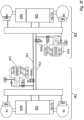
- the Figure 3b shows a possible embodiment of a vehicle with two vehicle axles A1 and A2 according to the invention, which are each supplied by their own pressure supply device DV1 and DV2.
- the axle A2 is not shown.
- the connection module VM makes it possible to connect the two hydraulic circuits of the two axles A1 and A2. If one pressure supply device fails, the other still intact pressure supply device can take over the pressure control for all components of the vehicle, which ensures a high level of error safety and redundancy.
- the connection module VM also enables a connection to the storage tank VB.
- the internal structure of the connection module is not described in detail here. However, in a simple design it is possible to manage with just three switching valves.
- Additional hydraulically assisted H-EMB parking brakes are installed on the wheel brakes. Their function is already Figure 2 described in detail.
- a reservoir VB supplies the pressure supply device DV1 with hydraulic fluid and it can be replenished.
- a VB2 with separate chambers K1 and K2 supplies the pressure supply device DV2 with hydraulic fluid and pressure can be released into the reservoir via the connection module VM.
- pressure must be released from the hydraulic circuit of axis A2 because axis A2 does not have an actuating unit BE, which is typically designed hydraulically with a separate reservoir (not shown). This allows excess pressure in the hydraulic circuit of axis A1 to escape via the actuating unit BE.
- the actuating unit BE is connected to the hydraulic circuit of axis A1 via a normally open valve TVBE, so that if both fail, pressure supply devices or a pressure in the wheel brakes of axle A1 a braking pressure can be built up.
- FIG. 3a The pressure supply and control of the gearbox is in Figure 3a described in detail. Reference is made to the explanations therein.
- a media separation MTK between the brake circuit and the transmission circuit is optionally provided.
- the optional media separation piston MTK enables a different medium to be used for transmission actuation than for brake actuation. Therefore, a separate reservoir VB3 is provided, into which the volume is drained during clutch actuation. This reservoir is in turn connected to the MTK module.
- FIG. 3b Another difference of the Figure 3b to Figure 3a is that a H-EMB is used. This mode of action is in Figures 2a and 2b described in detail.
- additional hydraulic actuators for torque vectoring HS-TV are provided, which are controlled via solenoid valve(s) MV-TV.
- the torque vectoring module HS-TV can be integrated in the gearbox or installed separately (see dashed line)
- the Figure 3c shows another possible embodiment in which no actuating device BE is present.
- This corresponds to a vehicle structure with a pure electric brake pedal for fully autonomous driving.
- the connection module is designed in such a way that pressure can be released from the hydraulic circuits of both axles A1 and A2 into the storage tank VB.
- the pressure supplies DV1 and DV2 are connected to the storage tank VB, with each pressure supply being assigned a separate chamber K2, K3. Both pressure supplies can replenish from chambers K2 and K3 or, alternatively, via the VM module via chamber K1. This creates further redundancy and only one storage tank is required for all pressure supplies.
- the Figure 3d shows another possible embodiment of a vehicle axle with two pressure supply units DV1 and DV2.
- Each pressure supply device DV1, DV2 controls a wheel brake RB1, RB2 and a part the manual transmission actuation SG.
- the wheel brakes and manual transmission actuations are connected to the respective pressure supply unit via solenoid valves that are preferably open when de-energized.
- at least one media separation piston MTK can be installed so that the brakes can be operated with a different hydraulic medium than the manual transmission SG.
- the associated switching valve SV1, SV2 is opened and the valve of the associated transmission actuation is closed.
- the valve switching is reversed. Braking has priority over switching the manual transmission SG.
- the pressure supply device is permanently connected to the respective wheel brake during pressure modulation when braking. Switching can take place during braking phases with constant pressure or after braking.
- the Figure 4 shows a possible embodiment of a pressure supply device DV1 with two control and regulating devices DV-ECU1 and DV-ECU2.
- the pressure supply device has an electric motor M1, the rotor R of which adjusts a spindle SP, which is connected to a piston KB.
- a pressure in the pressure chamber DR can be set up, which can be fed into a brake circuit BK via the isolating valve TV.
- the piston is sealed by several seals in the cylinder, with a hydraulic line leading to the reservoir between each seal. This means that the pressure supply is still fully operational and redundant even if one seal fails.
- the pressure chamber DR is connected to the reservoir via a check valve. This means that the pressure supply can continue to pump.
- Each of the two control and regulating devices DV-ECU1 and DV-ECU2 are connected to separate winding or phase systems of the motor M1 via 1x3 phase lines, so that if one control and regulating device or winding system fails, the motor M1 can still be operated via the other winding or phase system and the other control and regulating device, even if only about half the torque can then be generated by the M1 drive.
- One or both control and regulating devices have sensors for determining the temperature T, the motor current i and the rotor angle ⁇ .
- power supplies BN1, BN2 and data and control lines DS1 and DS2 are also provided in duplicate.
- the power supplies BN1 and BN2 can be, for example, different voltage levels of an on-board network or separate on-board networks.
- the Figure 5 shows a possible embodiment of a pressure supply device DV in the form of a double-acting piston with 2 pressure chambers and different areas A1 and A2, whereby the area ratio A1/A2 is preferably between 1.5 and 2.5.
- the DV also has two control and regulating devices DV-ECU1 and DV-ECU2.
- the pressure supply device has an electric motor M1, the rotor R of which adjusts a spindle SP, which is connected to a piston KB. By adjusting the piston KB, a pressure can be built up in the pressure chamber DR, which can be fed into a brake circuit BK via the isolating valve TV.
- the piston is sealed in the cylinder via several seals, whereby, as with the pressure supply device, a redundant, diagnosable sealing system is created.
- the pressure supply device also has a pressure between The seals each have a hydraulic line to the reservoir. This means that the seals can be diagnosed and the pressure supply is still fully operational and redundant even if one seal fails.
- the pressure chambers DRx and DRx are connected to the reservoir via check valves and valves xx and xx. This means that the pressure supply can draw volume from the reservoir into both pressure chambers Dxx and Dxx and a controlled pressure reduction is possible via both pressure chambers into the reservoir.
- the pressure reduction can take place via piston control or valve control, e.g. by PWM timing of the valves.
- the pressure sensors p/u are advantageously used for pressure control; PPC control can be used additionally or alternatively.
- the two hydraulic circuits HKI and HK II are connected via one or more bypass valve(s), which are preferably designed to be closed when de-energized.
- the pressure build-up in HK1 and HK2 can therefore take place in the forward and reverse stroke directions.
- the effective area of the piston in the forward and return stroke direction can be reduced because when the bypass valve circuit is open, A1-A2 is effective in the forward stroke direction and A2 in the return stroke direction. This means that the torque requirement for the electric motor can be reduced, costs can be saved and the load on the gearbox can be reduced due to lower axial forces.
- Each of the two control and regulating devices DV-ECU1 and DV-ECU2 are connected to separate winding or phase systems of the motor M1 via 1x3 phase lines, so that if one control and regulating device or winding system fails, the motor M1 can still be operated via the other winding or phase system and the other control and regulating device, even if only about half the torque can then be generated by the drive M1.
- One or both control and regulating devices have sensors for determining the temperature T, the motor current i and the rotor angle ⁇ of the electric motor.
- the power supplies BN1, BN2 and the data and control lines DS1 and DS2 are provided in duplicate.
- the power supplies BN1 and BN2 can, for example, be different voltage levels of an on-board network or separate on-board networks.
- the Figure 6 shows a brake pressure control in the event of a failure of the pressure sensor DG, whereby the motor torque M Mot and thus the pressure p are controlled by measuring the motor current i phase and evaluating the pressure-volume characteristic.
- the motor temperature T is also taken into account, since the torque constant is reduced at higher temperatures and thus has an influence on the proportionality factor kt * (1-Br%* ⁇ T) between the motor torque M Mot and the motor current i phase . This advantageously results in redundancy of the pressure measurement.
- a pressure sensor can be dispensed with.
- the control is calibrated by the pressure sensor and it is primarily controlled using the current, travel and pressure-volume characteristic.
- the PPC procedure (see introduction DE102005055751B4 and DE102005018649B4 ) can be refined and is used for braking, steering, clutches, torque vectoring with clutch release.
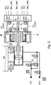
- the Fig. 8a shows a representation of an entire assembly consisting of motor 22, pump Z, HCU and ECU, which is able to exercise pressure regulation and control for systems such as brakes, transmission, etc.
- the combination of motor and pump is essentially shown here.
- the pump is arranged in the bearing flange 18 or in a separate pump housing 40, as shown in the upper half of the picture, attached to the HCU or ECU.
- Fig. 8a A version is shown which requires an additional motor bearing 20 in which the shaft 1 is mounted.
- the motor consists as usual, consists of rotor 21, which is connected to shaft 1 via driver 10a. Rotor 21 is axially preloaded by the force of a permanent magnet in housing 30.
- the motor is shown here as a brushless motor, which requires a motor sensor for commutation and control of the volumetric delivery of the pump.
- This motor sensor is arranged away from the drive housing 22, with a sensor shaft 26, which is arranged or attached to the drive shaft 1, carrying a sensor target 27.
- This target 27 acts on the sensor element 28, which is arranged on the circuit board of the ECU.
- the winding is connected to the ECU via contact rails 24.
- the motor with bearing flange 18 can be connected directly to the hydraulic housing HCU, which contains valves or other hydraulic components, with the pump. If this is not the case, it is advisable to connect the drive housing 22, 18 directly to the housing of the ECU.
- the gear pump Z is also possible to arrange the gear pump Z in a pump housing 40 which is directly connected to the hydraulic housing HCU, as shown in Figure 8a in the upper half of the drive shaft 1.
- the gear pump Z is first integrated or mounted in the pump housing 40, whereby the rotor 21 is then pressed onto the shaft 1 and then assembled with the bearing 20.
- the pulling force of the magnet 30 can also be applied to the rotor 21 and the bearing 20, whereby the bearing acts like a four-point bearing.
- the motor housing 22 is thus connected to the gear pump Z and its pump housing 40 and can be connected to the hydraulic housing HCU or the electronics housing ECU in the next step.
- the fastening screw 41 is used for this.
- the shaft 1 is previously centered in the outer disks 7.1 and 7.2 so that the pump housing 40 is centered with the shaft 1 before being screwed to the hydraulic housing HCU or the electronics housing ECU.
- the pressure supply device uses a 2-stage pump with long plain or roller bearings, which does not require a separate motor bearing. Accordingly, the motor structure with housing is simplified.
- the rotor 21 sits on the motor shaft with driver 10a and is axially connected to the locking ring.
- the pump housing protrudes slightly into the HCU here.
Landscapes
- Engineering & Computer Science (AREA)
- Transportation (AREA)
- Mechanical Engineering (AREA)
- Regulating Braking Force (AREA)
- Valves And Accessory Devices For Braking Systems (AREA)
Applications Claiming Priority (4)
| Application Number | Priority Date | Filing Date | Title |
|---|---|---|---|
| DE102018133223.8A DE102018133223A1 (de) | 2018-12-20 | 2018-12-20 | Fahrzeugachse mit elektrischen Antriebsmotoren und elektrohydraulischer Bremse und weiterer Module wie Getriebe, Torque Vektoring und Parkbremse |
| EP19831586.3A EP3898359B1 (fr) | 2018-12-20 | 2019-12-20 | Essieu de véhicule avec propulsion électrique, frein électro-hydraulique et modules additionnels comme engrenage, vecteur de couple, et frein de stationnement |
| EP22203469.6A EP4169781B1 (fr) | 2018-12-20 | 2019-12-20 | Essieu de véhicule avec moteurs d'entraînement électriques et frein électrohydraulique et autres modules tels que boîte de vitesses, torque vectoring et frein de stationnement |
| PCT/EP2019/086870 WO2020128081A1 (fr) | 2018-12-20 | 2019-12-20 | Essieu de véhicule comprenant des moteurs d'entraînement électriques et un frein électrohydraulique et d'autres modules tels qu'engrenage, vecteur de couple et frein de stationnement |
Related Parent Applications (2)
| Application Number | Title | Priority Date | Filing Date |
|---|---|---|---|
| EP22203469.6A Division EP4169781B1 (fr) | 2018-12-20 | 2019-12-20 | Essieu de véhicule avec moteurs d'entraînement électriques et frein électrohydraulique et autres modules tels que boîte de vitesses, torque vectoring et frein de stationnement |
| EP19831586.3A Division EP3898359B1 (fr) | 2018-12-20 | 2019-12-20 | Essieu de véhicule avec propulsion électrique, frein électro-hydraulique et modules additionnels comme engrenage, vecteur de couple, et frein de stationnement |
Publications (2)
| Publication Number | Publication Date |
|---|---|
| EP4454961A2 true EP4454961A2 (fr) | 2024-10-30 |
| EP4454961A3 EP4454961A3 (fr) | 2025-03-05 |
Family
ID=69159744
Family Applications (3)
| Application Number | Title | Priority Date | Filing Date |
|---|---|---|---|
| EP19831586.3A Active EP3898359B1 (fr) | 2018-12-20 | 2019-12-20 | Essieu de véhicule avec propulsion électrique, frein électro-hydraulique et modules additionnels comme engrenage, vecteur de couple, et frein de stationnement |
| EP22203469.6A Active EP4169781B1 (fr) | 2018-12-20 | 2019-12-20 | Essieu de véhicule avec moteurs d'entraînement électriques et frein électrohydraulique et autres modules tels que boîte de vitesses, torque vectoring et frein de stationnement |
| EP24188961.7A Pending EP4454961A3 (fr) | 2018-12-20 | 2019-12-20 | Essieu de véhicule avec moteurs d'entraînement électriques et frein électrohydraulique et autres modules tels que boîte de vitesses, torque vectoring et frein de stationnement |
Family Applications Before (2)
| Application Number | Title | Priority Date | Filing Date |
|---|---|---|---|
| EP19831586.3A Active EP3898359B1 (fr) | 2018-12-20 | 2019-12-20 | Essieu de véhicule avec propulsion électrique, frein électro-hydraulique et modules additionnels comme engrenage, vecteur de couple, et frein de stationnement |
| EP22203469.6A Active EP4169781B1 (fr) | 2018-12-20 | 2019-12-20 | Essieu de véhicule avec moteurs d'entraînement électriques et frein électrohydraulique et autres modules tels que boîte de vitesses, torque vectoring et frein de stationnement |
Country Status (5)
| Country | Link |
|---|---|
| US (3) | US12084012B2 (fr) |
| EP (3) | EP3898359B1 (fr) |
| CN (5) | CN118810711A (fr) |
| DE (2) | DE102018133223A1 (fr) |
| WO (1) | WO2020128081A1 (fr) |
Families Citing this family (27)
| Publication number | Priority date | Publication date | Assignee | Title |
|---|---|---|---|---|
| DE102020202477A1 (de) | 2020-02-26 | 2021-08-26 | Volkswagen Aktiengesellschaft | Sicherheitssystem für einen elektrisch antreibbaren Kraftwagen, Verfahren zum Betreiben eines solchen Sicherheitssystems sowie Kraftwagen |
| DE102021100921A1 (de) | 2021-01-18 | 2022-07-21 | Audi Aktiengesellschaft | Elektrohydraulischer Achsmomentensteller |
| CN112959983A (zh) * | 2021-02-02 | 2021-06-15 | 中船第九设计研究院工程有限公司 | 一种液压台车启停保护用双重制动机构 |
| DE102021201046A1 (de) * | 2021-02-04 | 2022-08-04 | Continental Teves Ag & Co. Ohg | Verfahren zur Steuerung eines Bremssystems |
| DE102021202221A1 (de) | 2021-03-08 | 2022-09-08 | Knorr-Bremse Systeme für Nutzfahrzeuge GmbH | Redundante Ausführung eines elektromechanischen Bremssystems |
| DE102021108523A1 (de) | 2021-04-06 | 2022-10-06 | Audi Aktiengesellschaft | Bremssystem für ein autonomes Fahrzeug |
| DE102021108524A1 (de) | 2021-04-06 | 2022-10-06 | Audi Aktiengesellschaft | Bremssystem für ein autonomes Fahrzeug |
| US12135065B2 (en) * | 2021-07-13 | 2024-11-05 | ZF Active Safety US Inc. | Electronic parking brake |
| DE102021210786A1 (de) * | 2021-09-28 | 2023-03-30 | Vitesco Technologies GmbH | Einrichtung und Verfahren zur Verhinderung eines Wegrollens eines geparkten Fahrzeugs |
| DE102021133569B4 (de) * | 2021-12-17 | 2025-02-06 | Dr. Ing. H.C. F. Porsche Aktiengesellschaft | Verfahren zum Betreiben eines Brake-by-wire-Bremssystems und Brake-by-wire-Bremssystem für ein Kraftfahrzeug |
| US12113423B2 (en) * | 2022-02-14 | 2024-10-08 | Dana Motion Systems Italia S.R.L. | Electric motor with integrated pump |
| DE102022103839B3 (de) | 2022-02-17 | 2023-03-30 | Audi Aktiengesellschaft | Antriebsvorrichtung für eine Fahrzeugachse |
| DE102022104852A1 (de) | 2022-03-01 | 2023-09-07 | Zf Active Safety Gmbh | Bremssystem, Fahrzeug und Verfahren zum Betreiben eines Bremssystems |
| US20250282228A1 (en) | 2022-05-05 | 2025-09-11 | Ipgate Ag | Driving dynamics system, vehicle and method for operating a driving dynamics system |
| EP4554827B1 (fr) * | 2022-07-12 | 2026-04-01 | Stellantis Europe S.p.A. | Système et procédé de génération de pression hydraulique pour actionner un système de freinage de véhicule automobile |
| CN115140001B (zh) * | 2022-08-17 | 2024-05-03 | 杭叉集团股份有限公司 | 一种重装电动叉车电液复合制动系统及控制方法 |
| DE102022209494A1 (de) * | 2022-09-12 | 2024-03-14 | Robert Bosch Gesellschaft mit beschränkter Haftung | Verfahren zum Betreiben eines Steuergeräts für ein Parkbremsensystem |
| DE102023102942A1 (de) | 2023-02-07 | 2024-08-08 | Audi Aktiengesellschaft | Antriebsvorrichtung für eine Fahrzeugachse |
| DE102023102939B4 (de) | 2023-02-07 | 2024-10-10 | Audi Aktiengesellschaft | Antriebsvorrichtung für eine Fahrzeugachse |
| DE102023102933B4 (de) | 2023-02-07 | 2024-09-19 | Audi Aktiengesellschaft | Antriebsvorrichtung für eine Fahrzeugachse mit Torque-Vectoring-Funktion und Bremsfunktion |
| CN116039587B (zh) * | 2023-03-30 | 2023-06-20 | 小米汽车科技有限公司 | 制动控制方法、装置、系统、车辆、介质及芯片 |
| DE102023203907A1 (de) * | 2023-04-27 | 2024-10-31 | Robert Bosch Gesellschaft mit beschränkter Haftung | Verfahren zur Steuerung eines radindividuellen, elektrohydraulischen Bremsaktuators; radindividueller, elektrohydraulischer Bremsaktuator und elektronisch schlupfregelbare Fremdkraftbremsanlage mit radindividuellem, elektrohydraulischem Bremsaktuator |
| DE102023114897A1 (de) | 2023-06-06 | 2024-12-12 | Audi Aktiengesellschaft | Bremsanlage für ein Kraftfahrzeug, Verfahren zum Betreiben der Bremsanlage sowie Kraftfahrzeug |
| DE102023114851A1 (de) | 2023-06-06 | 2024-12-12 | Audi Aktiengesellschaft | Bremssystem für ein Kraftfahrzeug, Verfahren zum Betreiben eines Bremssystems sowie Kraftfahrzeug |
| DE102023129984A1 (de) * | 2023-10-30 | 2025-04-30 | Audi Aktiengesellschaft | Antriebsvorrichtung für eine Fahrzeugachse |
| DE102024102956A1 (de) * | 2024-02-02 | 2025-08-07 | Zf Active Safety Gmbh | Fehlertolerantes Bremssystem für ein Kraftfahrzeug |
| DE102024134643B3 (de) | 2024-11-25 | 2026-05-07 | Dr. Ing. H.C. F. Porsche Aktiengesellschaft | Antriebsstrang eines elektrisch oder teilelektrisch angetriebenen Kraftfahrzeugs mit Torque-Vectoring-Einheit |
Citations (7)
| Publication number | Priority date | Publication date | Assignee | Title |
|---|---|---|---|---|
| EP2137427A1 (fr) | 2007-03-30 | 2009-12-30 | Ipgate Ag | Frein de parking électrique |
| EP1874602B1 (fr) | 2005-04-21 | 2012-12-05 | Ipgate Ag | Commande de modulateur de pression |
| EP1759447B1 (fr) | 2004-06-23 | 2013-07-10 | Thomas Leiber | Machine a champ tournant pourvue d'induits en cloche |
| EP2396202B1 (fr) | 2009-02-13 | 2015-04-29 | Ipgate Ag | Systeme de freinage avec diminution ou augmentation de pression dans les cylindres de frein simultanee ou partiellement simultanee a partir de niveaux differents de la pression dans les cylindres de frein |
| WO2016014622A1 (fr) | 2014-07-23 | 2016-01-28 | Fci Asia Pte. Ltd | Module connecteur optoélectrique |
| DE112009005541B3 (de) | 2009-02-03 | 2017-08-17 | Ipgate Ag | Bremssystem ohne Wegsimulator |
| DE102005018649B4 (de) | 2005-04-21 | 2018-10-31 | Ipgate Ag | Bremssystem mit elektromotorisch angetriebenem Kolben-Zylinder-System |
Family Cites Families (31)
| Publication number | Priority date | Publication date | Assignee | Title |
|---|---|---|---|---|
| DE3424912A1 (de) * | 1984-07-06 | 1986-01-16 | Alfred Teves Gmbh, 6000 Frankfurt | Elektronisch kontrolliertes bremsbetaetigungssystem |
| DE4415438A1 (de) * | 1994-05-03 | 1995-11-09 | Teves Gmbh Alfred | Elektronisch regelbares Bremsbetätigungssystem |
| DE19526250B4 (de) * | 1995-07-18 | 2005-02-17 | Daimlerchrysler Ag | Brems- und Lenksystem für ein Fahrzeug |
| DE10118263A1 (de) * | 2001-04-12 | 2002-10-17 | Bosch Gmbh Robert | Elektronisches Steuersystem, insbesondere für eine Fahrzeugbremsanlage |
| DE10223847A1 (de) * | 2001-05-30 | 2003-01-09 | Continental Teves Ag & Co Ohg | Verfahren zur Erhöhung der Lenkbarkeit und/oder der Fahrstabilität |
| CN101039830A (zh) | 2004-10-15 | 2007-09-19 | 大陆-特韦斯贸易合伙股份公司及两合公司 | 用于机动车辆的制动设备 |
| CN100577484C (zh) | 2004-10-15 | 2010-01-06 | 大陆-特韦斯贸易合伙股份公司及两合公司 | 用于机动车辆的制动设备 |
| DE102008049739B4 (de) * | 2008-09-30 | 2020-07-23 | Ipgate Ag | Zentrale Druckversorgung für Nebenantriebe |
| US9333957B2 (en) * | 2010-01-28 | 2016-05-10 | Continental Teves Ag & Co. Ohg | Method for operating a brake system for a motor vehicle and brake system |
| DE102011084206A1 (de) | 2010-10-12 | 2012-04-12 | Continental Teves Ag & Co. Ohg | Bremsanlage für Kraftfahrzeuge |
| AT12010U3 (de) * | 2011-04-04 | 2012-04-15 | Ve Vienna Engineering Forschungs Und Entwicklungs Gmbh | Elektrofahrzeug mit radindividuellen reibungsbremsen und radindividuellem antrieb und bremsverfahren dafür |
| JP2012240452A (ja) * | 2011-05-16 | 2012-12-10 | Advics Co Ltd | ブレーキ制御装置 |
| DE102012202467A1 (de) * | 2012-02-17 | 2013-08-22 | Continental Teves Ag & Co. Ohg | Verfahren zur Ansteuerung eines Bremssystems, Bremssystem und Verwendung |
| JP5960461B2 (ja) * | 2012-03-21 | 2016-08-02 | トヨタ自動車株式会社 | ブレーキ装置 |
| DE102013224870A1 (de) * | 2013-03-05 | 2014-09-11 | Continental Teves Ag & Co. Ohg | Bremsbetätigungseinheit |
| DE102013224313A1 (de) | 2013-03-05 | 2014-09-11 | Continental Teves Ag & Co. Ohg | Verfahren zum Betreiben eines Bremssystems |
| DE102013217954A1 (de) | 2013-09-09 | 2015-03-12 | Continental Teves Ag & Co. Ohg | Bremsanlage für ein Kraftfahrzeug und Betriebsverfahren |
| DE102013224776A1 (de) * | 2013-12-03 | 2015-06-03 | Continental Teves Ag & Co. Ohg | Bremssystem für ein Kraftfahrzeug |
| EP2998175B1 (fr) * | 2014-09-19 | 2018-07-25 | KNORR-BREMSE Systeme für Nutzfahrzeuge GmbH | Système de commande de direction supplémentaire |
| DE102014117726A1 (de) * | 2014-12-02 | 2016-06-02 | Ipgate Ag | Betätigungsanlage für eine Kraftfahrzeugbremse |
| WO2016146222A2 (fr) * | 2015-03-16 | 2016-09-22 | Ipgate Ag | Système de freinage équipé d'une unité à maître-cylindre de frein à régulation mux innovante (mux 2.0) comprenant au moins une soupape de sortie, et procédé servant à la régulation de pression |
| CN107428317A (zh) * | 2015-03-16 | 2017-12-01 | 爱皮加特股份公司 | 具有借助入口阀的特殊布线进行压力形成调节的具有制动回路/车轮制动器的制动装置和用于压力调节的方法 |
| KR102399337B1 (ko) * | 2015-10-29 | 2022-05-18 | 현대모비스 주식회사 | 차량의 전자식 제동 시스템 및 방법 |
| US10569657B2 (en) * | 2016-02-16 | 2020-02-25 | Toyota Jidosha Kabushiki Kaisha | Vehicle brake system |
| DE102016203563A1 (de) | 2016-03-04 | 2017-09-07 | Continental Teves Ag & Co. Ohg | Bremsanlage mit zwei Druckbereitstellungseinrichtungen sowie Verfahren zum Betreiben einer Bremsanlage |
| CN107472232B (zh) * | 2016-06-08 | 2021-09-14 | 爱皮加特股份公司 | 用于制动系统的诊断方法 |
| JP6485418B2 (ja) * | 2016-08-09 | 2019-03-20 | トヨタ自動車株式会社 | ブレーキ制御装置 |
| DE102016225537A1 (de) * | 2016-12-20 | 2018-06-21 | Continental Teves Ag & Co. Ohg | Bremssystem mit zwei Druckquellen und Verfahren zum Betreiben eines Bremssystems |
| DE102017111077A1 (de) * | 2017-05-22 | 2018-11-22 | Lsp Innovative Automotive Systems Gmbh | Bremsvorrichtung, insbesondere für elektrisch angetriebene Kraftfahrzeuge |
| DE102017114556A1 (de) * | 2017-06-29 | 2019-01-03 | Ipgate Ag | Vorrichtung für ein hydraulisches Betätigungssystem |
| EP4653272A2 (fr) * | 2018-12-20 | 2025-11-26 | Ipgate Ag | Système de freinage redondant avec alimentation en pression pour véhicules électriques et véhicules avec conduite autonome du niveau 3 (had) jusqu'à 4 (fad) |
-
2018
- 2018-12-20 DE DE102018133223.8A patent/DE102018133223A1/de not_active Withdrawn
-
2019
- 2019-12-20 EP EP19831586.3A patent/EP3898359B1/fr active Active
- 2019-12-20 CN CN202411072115.1A patent/CN118810711A/zh active Pending
- 2019-12-20 WO PCT/EP2019/086870 patent/WO2020128081A1/fr not_active Ceased
- 2019-12-20 CN CN202410228650.5A patent/CN118372791A/zh active Pending
- 2019-12-20 DE DE112019006371.5T patent/DE112019006371A5/de active Pending
- 2019-12-20 CN CN201980092241.4A patent/CN113453967B/zh active Active
- 2019-12-20 US US17/415,294 patent/US12084012B2/en active Active
- 2019-12-20 CN CN202411072013.XA patent/CN118790211A/zh active Pending
- 2019-12-20 EP EP22203469.6A patent/EP4169781B1/fr active Active
- 2019-12-20 EP EP24188961.7A patent/EP4454961A3/fr active Pending
- 2019-12-20 CN CN202411072061.9A patent/CN118810710A/zh active Pending
-
2024
- 2024-04-05 US US18/628,001 patent/US12263819B2/en active Active
- 2024-08-05 US US18/794,203 patent/US20240391439A1/en active Pending
Patent Citations (8)
| Publication number | Priority date | Publication date | Assignee | Title |
|---|---|---|---|---|
| EP1759447B1 (fr) | 2004-06-23 | 2013-07-10 | Thomas Leiber | Machine a champ tournant pourvue d'induits en cloche |
| EP1874602B1 (fr) | 2005-04-21 | 2012-12-05 | Ipgate Ag | Commande de modulateur de pression |
| DE102005055751B4 (de) | 2005-04-21 | 2018-09-06 | Ipgate Ag | Druckmodulatorsteuerung |
| DE102005018649B4 (de) | 2005-04-21 | 2018-10-31 | Ipgate Ag | Bremssystem mit elektromotorisch angetriebenem Kolben-Zylinder-System |
| EP2137427A1 (fr) | 2007-03-30 | 2009-12-30 | Ipgate Ag | Frein de parking électrique |
| DE112009005541B3 (de) | 2009-02-03 | 2017-08-17 | Ipgate Ag | Bremssystem ohne Wegsimulator |
| EP2396202B1 (fr) | 2009-02-13 | 2015-04-29 | Ipgate Ag | Systeme de freinage avec diminution ou augmentation de pression dans les cylindres de frein simultanee ou partiellement simultanee a partir de niveaux differents de la pression dans les cylindres de frein |
| WO2016014622A1 (fr) | 2014-07-23 | 2016-01-28 | Fci Asia Pte. Ltd | Module connecteur optoélectrique |
Also Published As
| Publication number | Publication date |
|---|---|
| CN113453967B (zh) | 2024-08-20 |
| DE112019006371A5 (de) | 2021-09-30 |
| DE102018133223A1 (de) | 2020-06-25 |
| EP3898359A1 (fr) | 2021-10-27 |
| EP3898359B1 (fr) | 2023-02-08 |
| US20240300463A1 (en) | 2024-09-12 |
| US12084012B2 (en) | 2024-09-10 |
| US20220055593A1 (en) | 2022-02-24 |
| CN118372791A (zh) | 2024-07-23 |
| CN118810710A (zh) | 2024-10-22 |
| CN118810711A (zh) | 2024-10-22 |
| CN118790211A (zh) | 2024-10-18 |
| EP4169781A1 (fr) | 2023-04-26 |
| EP4169781C0 (fr) | 2024-07-31 |
| EP4454961A3 (fr) | 2025-03-05 |
| EP4169781B1 (fr) | 2024-07-31 |
| CN113453967A (zh) | 2021-09-28 |
| WO2020128081A1 (fr) | 2020-06-25 |
| US12263819B2 (en) | 2025-04-01 |
| US20240391439A1 (en) | 2024-11-28 |
Similar Documents
| Publication | Publication Date | Title |
|---|---|---|
| EP4169781B1 (fr) | Essieu de véhicule avec moteurs d'entraînement électriques et frein électrohydraulique et autres modules tels que boîte de vitesses, torque vectoring et frein de stationnement | |
| EP4147925B1 (fr) | Système de freinage redondant avec 2 alimentations en pression pour les véhicules électriques et les véhicules à conduite autonome de niveau 3 (had) à niveau 5 (ad) | |
| EP4219255B1 (fr) | Système de freinage redondant avec une alimentation en pression pour les véhicules électriques et les véhicules à conduite autonome de niveau 3 (had) à niveau 4 (fad) | |
| EP4523980B1 (fr) | Système de dynamique de conduite | |
| EP3924226B1 (fr) | Système de freinage comportant au moins deux circuits hydrauliques et au moins deux dispositifs compresseurs | |
| EP4096977B1 (fr) | Système de freinage et procédé de commande d'un système de freinage | |
| DE102018133218A1 (de) | Redundantes Bremssystem mit einer Druckversorgung für E-Fahrzeuge und Fahrzeuge mit autonomem Fahren der Stufe 3 (HAD) bis Stufe 4 (FAD) | |
| DE102018133189A1 (de) | Redundantes Bremssystem mit 2 Druckversorgungen für Elektrofahrzeuge und Fahrzeuge mit autonomem Fahren der Stufe 3 (HAD) bis Stufe 5 (AD) | |
| DE202015008975U1 (de) | Bremsanlage mit Schwimmkolben-Hauptbremszylindereinheit mit neuartiger MUX-Regelung (MUX 2.0) mit mindestens einem Auslassventil | |
| EP4635808A1 (fr) | Système de freinage avec dispositif d'alimentation en pression et sécurité pour les circuits de freinage | |
| DE202019107193U1 (de) | Bremsvorrichtung, insbesondere für elektrisch angetriebene Kraftfahrzeuge | |
| DE102022204955A1 (de) | Bremssystem für Kraftfahrzeuge mit einem Aktuator |
Legal Events
| Date | Code | Title | Description |
|---|---|---|---|
| PUAI | Public reference made under article 153(3) epc to a published international application that has entered the european phase |
Free format text: ORIGINAL CODE: 0009012 |
|
| STAA | Information on the status of an ep patent application or granted ep patent |
Free format text: STATUS: REQUEST FOR EXAMINATION WAS MADE |
|
| REG | Reference to a national code |
Ref country code: DE Ref legal event code: R079 Free format text: PREVIOUS MAIN CLASS: B60T0013660000 Ipc: B60T0013580000 |
|
| 17P | Request for examination filed |
Effective date: 20240723 |
|
| AC | Divisional application: reference to earlier application |
Ref document number: 3898359 Country of ref document: EP Kind code of ref document: P Ref document number: 4169781 Country of ref document: EP Kind code of ref document: P |
|
| AK | Designated contracting states |
Kind code of ref document: A2 Designated state(s): AL AT BE BG CH CY CZ DE DK EE ES FI FR GB GR HR HU IE IS IT LI LT LU LV MC MK MT NL NO PL PT RO RS SE SI SK SM TR |
|
| RIC1 | Information provided on ipc code assigned before grant |
Ipc: B60T 13/00 20060101ALI20241007BHEP Ipc: B60T 13/66 20060101ALI20241007BHEP Ipc: B60T 13/74 20060101ALI20241007BHEP Ipc: B60T 13/58 20060101AFI20241007BHEP |
|
| PUAL | Search report despatched |
Free format text: ORIGINAL CODE: 0009013 |
|
| AK | Designated contracting states |
Kind code of ref document: A3 Designated state(s): AL AT BE BG CH CY CZ DE DK EE ES FI FR GB GR HR HU IE IS IT LI LT LU LV MC MK MT NL NO PL PT RO RS SE SI SK SM TR |
|
| RIC1 | Information provided on ipc code assigned before grant |
Ipc: B60T 13/00 20060101ALI20250128BHEP Ipc: B60T 13/66 20060101ALI20250128BHEP Ipc: B60T 13/74 20060101ALI20250128BHEP Ipc: B60T 13/58 20060101AFI20250128BHEP |
|
| STAA | Information on the status of an ep patent application or granted ep patent |
Free format text: STATUS: EXAMINATION IS IN PROGRESS |
|
| 17Q | First examination report despatched |
Effective date: 20251104 |
|
| RAP1 | Party data changed (applicant data changed or rights of an application transferred) |
Owner name: IPGATE AG |