EP4455014A1 - Dérivation de compresseur d'air de cabine pour éviter les surtensions - Google Patents
Dérivation de compresseur d'air de cabine pour éviter les surtensions Download PDFInfo
- Publication number
- EP4455014A1 EP4455014A1 EP24172172.9A EP24172172A EP4455014A1 EP 4455014 A1 EP4455014 A1 EP 4455014A1 EP 24172172 A EP24172172 A EP 24172172A EP 4455014 A1 EP4455014 A1 EP 4455014A1
- Authority
- EP
- European Patent Office
- Prior art keywords
- medium
- compressor
- control system
- heat exchanger
- environmental control
- Prior art date
- Legal status (The legal status is an assumption and is not a legal conclusion. Google has not performed a legal analysis and makes no representation as to the accuracy of the status listed.)
- Pending
Links
Images

Classifications
-
- B—PERFORMING OPERATIONS; TRANSPORTING
- B64—AIRCRAFT; AVIATION; COSMONAUTICS
- B64D—EQUIPMENT FOR FITTING IN OR TO AIRCRAFT; FLIGHT SUITS; PARACHUTES; ARRANGEMENT OR MOUNTING OF POWER PLANTS OR PROPULSION TRANSMISSIONS IN AIRCRAFT
- B64D13/00—Arrangements or adaptations of air-treatment apparatus for aircraft crew or passengers, or freight space
- B64D13/06—Arrangements or adaptations of air-treatment apparatus for aircraft crew or passengers, or freight space the air being conditioned
-
- F—MECHANICAL ENGINEERING; LIGHTING; HEATING; WEAPONS; BLASTING
- F25—REFRIGERATION OR COOLING; COMBINED HEATING AND REFRIGERATION SYSTEMS; HEAT PUMP SYSTEMS; MANUFACTURE OR STORAGE OF ICE; LIQUEFACTION SOLIDIFICATION OF GASES
- F25B—REFRIGERATION MACHINES, PLANTS OR SYSTEMS; COMBINED HEATING AND REFRIGERATION SYSTEMS; HEAT PUMP SYSTEMS
- F25B49/00—Arrangement or mounting of control or safety devices
- F25B49/02—Arrangement or mounting of control or safety devices for compression type machines, plants or systems
- F25B49/022—Compressor control arrangements
-
- B—PERFORMING OPERATIONS; TRANSPORTING
- B64—AIRCRAFT; AVIATION; COSMONAUTICS
- B64D—EQUIPMENT FOR FITTING IN OR TO AIRCRAFT; FLIGHT SUITS; PARACHUTES; ARRANGEMENT OR MOUNTING OF POWER PLANTS OR PROPULSION TRANSMISSIONS IN AIRCRAFT
- B64D13/00—Arrangements or adaptations of air-treatment apparatus for aircraft crew or passengers, or freight space
- B64D13/06—Arrangements or adaptations of air-treatment apparatus for aircraft crew or passengers, or freight space the air being conditioned
- B64D13/08—Arrangements or adaptations of air-treatment apparatus for aircraft crew or passengers, or freight space the air being conditioned the air being heated or cooled
-
- F—MECHANICAL ENGINEERING; LIGHTING; HEATING; WEAPONS; BLASTING
- F25—REFRIGERATION OR COOLING; COMBINED HEATING AND REFRIGERATION SYSTEMS; HEAT PUMP SYSTEMS; MANUFACTURE OR STORAGE OF ICE; LIQUEFACTION SOLIDIFICATION OF GASES
- F25B—REFRIGERATION MACHINES, PLANTS OR SYSTEMS; COMBINED HEATING AND REFRIGERATION SYSTEMS; HEAT PUMP SYSTEMS
- F25B9/00—Compression machines, plants or systems, in which the refrigerant is air or other gas of low boiling point
- F25B9/002—Compression machines, plants or systems, in which the refrigerant is air or other gas of low boiling point characterised by the refrigerant
- F25B9/004—Compression machines, plants or systems, in which the refrigerant is air or other gas of low boiling point characterised by the refrigerant the refrigerant being air
-
- F—MECHANICAL ENGINEERING; LIGHTING; HEATING; WEAPONS; BLASTING
- F25—REFRIGERATION OR COOLING; COMBINED HEATING AND REFRIGERATION SYSTEMS; HEAT PUMP SYSTEMS; MANUFACTURE OR STORAGE OF ICE; LIQUEFACTION SOLIDIFICATION OF GASES
- F25B—REFRIGERATION MACHINES, PLANTS OR SYSTEMS; COMBINED HEATING AND REFRIGERATION SYSTEMS; HEAT PUMP SYSTEMS
- F25B9/00—Compression machines, plants or systems, in which the refrigerant is air or other gas of low boiling point
- F25B9/06—Compression machines, plants or systems, in which the refrigerant is air or other gas of low boiling point using expanders
-
- B—PERFORMING OPERATIONS; TRANSPORTING
- B64—AIRCRAFT; AVIATION; COSMONAUTICS
- B64D—EQUIPMENT FOR FITTING IN OR TO AIRCRAFT; FLIGHT SUITS; PARACHUTES; ARRANGEMENT OR MOUNTING OF POWER PLANTS OR PROPULSION TRANSMISSIONS IN AIRCRAFT
- B64D13/00—Arrangements or adaptations of air-treatment apparatus for aircraft crew or passengers, or freight space
- B64D13/06—Arrangements or adaptations of air-treatment apparatus for aircraft crew or passengers, or freight space the air being conditioned
- B64D2013/0603—Environmental Control Systems
- B64D2013/0618—Environmental Control Systems with arrangements for reducing or managing bleed air, using another air source, e.g. ram air
-
- B—PERFORMING OPERATIONS; TRANSPORTING
- B64—AIRCRAFT; AVIATION; COSMONAUTICS
- B64D—EQUIPMENT FOR FITTING IN OR TO AIRCRAFT; FLIGHT SUITS; PARACHUTES; ARRANGEMENT OR MOUNTING OF POWER PLANTS OR PROPULSION TRANSMISSIONS IN AIRCRAFT
- B64D13/00—Arrangements or adaptations of air-treatment apparatus for aircraft crew or passengers, or freight space
- B64D13/06—Arrangements or adaptations of air-treatment apparatus for aircraft crew or passengers, or freight space the air being conditioned
- B64D2013/0603—Environmental Control Systems
- B64D2013/0644—Environmental Control Systems including electric motors or generators
-
- B—PERFORMING OPERATIONS; TRANSPORTING
- B64—AIRCRAFT; AVIATION; COSMONAUTICS
- B64D—EQUIPMENT FOR FITTING IN OR TO AIRCRAFT; FLIGHT SUITS; PARACHUTES; ARRANGEMENT OR MOUNTING OF POWER PLANTS OR PROPULSION TRANSMISSIONS IN AIRCRAFT
- B64D13/00—Arrangements or adaptations of air-treatment apparatus for aircraft crew or passengers, or freight space
- B64D13/06—Arrangements or adaptations of air-treatment apparatus for aircraft crew or passengers, or freight space the air being conditioned
- B64D2013/0603—Environmental Control Systems
- B64D2013/0648—Environmental Control Systems with energy recovery means, e.g. using turbines
-
- F—MECHANICAL ENGINEERING; LIGHTING; HEATING; WEAPONS; BLASTING
- F25—REFRIGERATION OR COOLING; COMBINED HEATING AND REFRIGERATION SYSTEMS; HEAT PUMP SYSTEMS; MANUFACTURE OR STORAGE OF ICE; LIQUEFACTION SOLIDIFICATION OF GASES
- F25B—REFRIGERATION MACHINES, PLANTS OR SYSTEMS; COMBINED HEATING AND REFRIGERATION SYSTEMS; HEAT PUMP SYSTEMS
- F25B2400/00—Component parts or details not otherwise provided for in this subclass
- F25B2400/04—Refrigeration circuit bypassing means
- F25B2400/0401—Refrigeration circuit bypassing means for compressors
-
- F—MECHANICAL ENGINEERING; LIGHTING; HEATING; WEAPONS; BLASTING
- F25—REFRIGERATION OR COOLING; COMBINED HEATING AND REFRIGERATION SYSTEMS; HEAT PUMP SYSTEMS; MANUFACTURE OR STORAGE OF ICE; LIQUEFACTION SOLIDIFICATION OF GASES
- F25B—REFRIGERATION MACHINES, PLANTS OR SYSTEMS; COMBINED HEATING AND REFRIGERATION SYSTEMS; HEAT PUMP SYSTEMS
- F25B2600/00—Control issues
- F25B2600/25—Control of valves
- F25B2600/2501—Bypass valves
Definitions
- Exemplary embodiments pertain to the art of thermal management and, in particular, to thermal management of one or more loads of a vehicle.
- Environmental control systems are utilized on various types of aircraft for several purposes, such as air supply systems and/or cabin condition systems for the aircraft.
- components of the environmental control system may be utilized to remove heat from various aircraft lubrication and electrical systems and/or used to condition aircraft cabin air.
- a cabin air conditioning may include one or more cabin air compressing devices (CAC) which compress air entering the system from an outside source or from a ram air system. The compressed air is typically delivered to an environmental control system pack to bring it to a desired temperature then delivered to the aircraft cabin. After passing through the cabin, the air is typically exhausted to the outside.
- CACs may be driven, for example, by air-cooled electric motors.
- an environmental control system for a vehicle includes a source of a first medium, a cabin air compressing device including a compressor having a compressor inlet and a compressor outlet, and a conduit fluidly coupling the source of the first medium to the compressor inlet.
- the first medium provided to the compressor inlet is output at the compressor outlet as a compressed first medium.
- An environmental control system pack is located downstream from and is fluidly coupled to the compressor outlet.
- the environmental control system pack includes a ram air circuit having at least one ram air heat exchanger. Another conduit for providing a second medium to the compressor fluidly couples an outlet of the at least one ram air heat exchanger and the compressor inlet.
- a pressure of the second medium is equal to a pressure of the compressed first medium.
- a pressure of the second medium is greater than a pressure of the compressed first medium.
- the second medium is the compressed first medium.
- the at least one ram air heat exchanger further comprises a primary heat exchanger and a secondary heat exchanger.
- the another conduit is fluidly connected to an outlet of the primary heat exchanger.
- the at least one ram air heat exchanger further comprises a primary heat exchanger and a secondary heat exchanger.
- the another conduit is fluidly connected to an outlet of the secondary heat exchanger.
- the cabin air compressing device further includes a shaft connected to the compressor and an electric motor operably connected to the shaft and configured to drive the compressor.
- a valve is associated with the another conduit.
- the valve is operable to control a supply of the second medium provided to the compressor inlet.
- a controller is operable to move the valve between a plurality of positions to control the supply of the second medium provided to the compressor inlet.
- the first medium includes ram air.
- the first medium includes bleed air.
- the vehicle is an aircraft.
- a method of operating an environmental control system of a vehicle includes providing a first medium to a compressor inlet of a compressor of a cabin air compressing device via a conduit, compressing the first medium at the compressor to produce a compressed first medium, providing the compressed first medium to an environmental control system pack, and directing a flow of a second medium provided at an outlet of a ram air heat exchanger of the environmental control system pack to the compressor inlet.
- directing the flow of the second medium to the compressor inlet includes operating a valve associated with another conduit.
- the another conduit fluidly connecting the outlet of the ram air heat exchanger and the compressor inlet.
- sensing a parameter at the compressor inlet and/ or a compressor outlet and operating the valve in response to the parameter In embodiments, sensing a parameter at the compressor inlet and/ or a compressor outlet and operating the valve in response to the parameter.
- the ram air heat exchanger is a primary heat exchanger.
- the ram air heat exchanger is a secondary heat exchanger.
- the second medium is the compressed first medium.
- the vehicle is an aircraft.
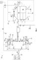
- the environmental control system 20 may be a refrigeration or air cycle subsystem and is configured to receive a first medium A at an inlet 22 from a first source 24 and/or at an inlet 26 from a second source 28.
- the first source 24 is an engine or auxiliary power unit of the aircraft and the medium A is bleed air.
- the first medium A provided to the inlet 26 may be fresh air, such as outside air for example.
- This outside air also referred to herein as RAM air, can be procured via one or more scooping mechanisms, such as an impact scoop or a flush scoop for example.
- the first medium A from the inlet 26 is generally at an ambient pressure equal to an air pressure outside of the aircraft when the aircraft is on the ground and is between an ambient pressure and a cabin pressure when the aircraft is in flight. It should be understood that any suitable first medium A is within the scope of the disclosure.
- suitable mediums available on an aircraft include, but are not limited to cabin discharge air, which is air leaving the cabin and that would typically be discharged overboard.
- Valves e.g., flow regulation device or mass flow valve
- Valves are devices that regulate, direct, and/or control a flow of a medium by opening, closing, or partially obstructing various passageways within the tubes, pipes, etc. of the system. Valves can be operated by actuators, such that flow rates of the medium in any portion of the environmental control system 20 can be regulated to a desired value.
- the environmental control system 20 includes at least one cabin air compressing device.
- the at least one cabin air compressing device includes a first cabin air compressing device 30a and a second cabin air compressing device 30b arranged in parallel.
- Each cabin air compressing device 30a, 30b is a mechanical device that includes one or more components for performing thermodynamic work on a medium (e.g., performs work on the medium by raising and/or lowering the pressure thereof and by raising and/or lowering the temperature thereof.)
- Each cabin air compressing device 30a, 30b includes a compressor 32.
- a compressor 32 is a mechanical device configured to raise a pressure of a medium and can be driven by another mechanical device (e.g., a motor or a medium via a turbine). Examples of compressor types include centrifugal, diagonal or mixed-flow, axial-flow, reciprocating, ionic liquid piston, rotary screw, rotary vane, scroll, diaphragm, air bubble, etc.
- the cabin air compressing device 30a, 30b additionally includes an electric motor 34, such as mounted to the shaft (not shown) of the compressor 32 to impart rotational motion thereto.
- the motor 34 can receive power from a power source (not shown) such as generator or a power bus (e.g., a power bus of an aircraft).
- a power source such as generator or a power bus (e.g., a power bus of an aircraft).
- the cabin air compressing device 30a, 30b may include additional components, such as a turbine for example. In embodiments including both a turbine and a motor 34 operably coupled to the compressor 32, either or all of the turbine and the motor 34 may be used to drive the compressor 32.
- the first medium A is provided to the environmental control system 20 from one or both of the inlet 22 and the inlet 26.
- the two flows merge or mix at a location upstream from the junction where the flow splits into a first flow of first medium A1a provided to the inlet 36 of the first cabin air compressing device 30a via a first pressure conduit 37 and a second flow of first medium A1b provided to the inlet 36 of the second cabin air compressing device 30b via a second conduit 38.
- the act of compressing the medium A1a or A1b heats the flow of medium A1a or A1b and increases the pressure of the thereof. Accordingly, at least one of a temperature and pressure of the compressed medium A1a' and A1b' provided at an outlet 39 of each compressor is greater than that of the medium A1a and A1b provided to the compressor inlet 36 of each respective compressor 32.
- the first flow of compressed first medium A1a' and/or the second flow of compressed first medium A1b' output from at least one of the cabin air compressing devices 30a, 30b may then be provided to a downstream component or system 40 before it is delivered to a volume of the vehicle, such as a cabin for example.
- the first flow of compressed first medium A1a' and the second flow of compressed first medium A1b' are combined upstream from the downstream component or system 40.
- the combined flow may simply be referred to as the compressed first medium.
- the first flow of compressed first medium A1a' and/or the second flow of compressed first medium A1b' output from at least one of the cabin air compressing devices 30a, 30b is provided to an ozone converter 70 located upstream from the downstream system or component 40.
- the ozone converter 70 is configured to convert ozone within the first and/or second flow of compressed first medium Ala', A1b' into oxygen.
- the resulting reduced-ozone first and/or second flow of compressed first medium Ala', A1b' may then be provided to the downstream system 40 for further conditioning.
- downstream system 40 is an environmental control system (ECS) pack 40 and at least one of the first flow of compressed first medium A1a' and the second flow of compressed first medium A1b' is provided to an inlet 41 thereof.
- the ECS pack 40 operable to condition the at least one of the first flow of compressed first medium A1a' and the second flow of compressed first medium A1b' for example.
- the ECS pack 40 may include a RAM air circuit 42 including a shell or duct, illustrated schematically at 44, within which one or more heat exchangers are located.
- the shell 44 can receive and direct a medium, such as ram air A R for example, through a portion of the ECS pack 40.
- the one or more heat exchangers are devices built for efficient heat transfer from one medium to another.
- Examples of the type of heat exchangers that may be used include, but are not limited to, double pipe, shell and tube, plate, plate and shell, adiabatic shell, plate fin, pillow plate, and fluid heat exchangers.
- Each of the one or more heat exchangers arranged within the shell 44 may be referred to as a ram air heat exchanger.
- the at least one ram air heat exchanger includes a first or primary heat exchanger 46 and a second or secondary heat exchanger 48.
- ram air AR such as outside air, acts as a heat sink to cool a medium passing there through, for example at least one of the first flow of compressed first medium A1a' and the second flow of compressed first medium A1b'output from one or both of the cabin air compressing devices 30a, 30b.
- the ECS pack 40 additionally comprises at least one thermodynamic device, illustrated schematically at 50.
- the thermodynamic device 50 of the system 20 is a mechanical device that includes components for performing thermodynamic work on a medium (e.g., extracts work from or applies work to the first flow of compressed first medium A1a' and/or the second flow of compressed first medium A1b' by raising and/or lowering pressure and by raising and/or lowering temperature).
- the thermodynamic device 50 include an air cycle machine, a three-wheel air cycle machine, a four-wheel air cycle machine, etc.
- the thermodynamic device 50 includes at least one compressor, such as compressor 52, and at least one turbine, such as a first turbine 54a and a second turbine 54b, coupled to each other via a shaft 56.
- the compressor 52 is a mechanical device that raises a pressure of a medium and can be driven by another mechanical device (e.g., a motor or a medium via a turbine).
- the one or more turbines 54a, 54b are mechanical devices that are operable to expand a medium and extract work therefrom (also referred to as extracting energy).
- the at least one turbine 54a, 54b may drive the compressor 52 via the shaft 56.
- the illustrated thermodynamic device 50 is intended as an example only and that a thermodynamic device having another configuration is also within the scope of the disclosure.
- another conduit 60 may be fluidly connected to the inlet 36 of compressor 32 to supply a flow of a second medium A2 thereto.
- the conduit 37, 38 coupled to the inlet 36 may be considered a primary inlet or flow path for supplying the first medium A1a or A1b to the compressor 36 and the conduit 60 may be considered a secondary inlet or secondary flow path for supplying a second medium A2 to a compressor 36 of at least one, or multiple cabin air compressing devices 30a, 30b.
- the conduit 60 includes a plurality of branches fluidly coupled to each of the plurality of cabin air compressing device 30a, 30b, respectively.
- a first branch 62 of the conduit 60 is connected at an end thereof to the conduit 37 and a second branch 63 of the conduit 60 is connected at an end thereof to the conduit 38.
- the first and second branches 62, 63 may connect to the conduits 37, 38 at a position downstream from the interface joining the first and second conduits 37, 38 and upstream from the inlet 36 of the compressor 32 associated with each respective conduit 37, 38 for example.
- Embodiments where one or more branches 62, 63 of the conduit 60 is directly connected to the inlet 36 of a compressor 32 are also within the scope of the disclosure.
- the compressor 32 may include a plurality of inlet openings, i.e., a first inlet opening (not shown) for receiving the first medium A1 from the primary conduit 37, 38 and a second inlet opening (not shown) for receiving the second medium A2 from the conduit 60, or a respective branch thereof.
- Providing a flow to the compressor 32 of each cabin air compressing device 30a, 30b separately, allows for operation of the compressors 32 at different speeds.
- the conduit 60 may be fluidly coupled to the cabin air compressing devices 30a, 30b at a location upstream from the interface joining the first and second conduits 37, 38.
- Such an embodiment may be suitable for use in embodiment where the compressors 32 of the cabin air compressing devices 30a, 30b are operating at the same speed.
- a valve may be arranged at the interface between the first and second conduits 37, 38 to control the flow provided to each compressor 32.
- the second medium A2 delivered to a compressor 32 of a cabin air compressing device 30a, 30b via conduit 60 may be the first flow of compressed first medium A1a' and/or the second flow of compressed first medium A1b' provided to the ECS pack 40 via inlet 41.
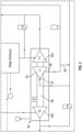
- the conduit 60 may be used to divert a portion of the first flow of compressed first medium A1a' and/or the second flow of compressed first medium A1b' provided at an outlet of a heat exchanger of the RAM air circuit 42, such as the primary heat exchanger 46 ( FIG. 1 ) or the secondary heat exchanger 48 ( FIG. 2 ) for example.
- an upstream end 64 of the conduit 60 may be fluidly coupled to an outlet of the primary heat exchanger 46 or the secondary heat exchanger 48, respectively.
- the end 64 of the conduit 60 may be fluidly coupled to the ECS pack 40 downstream from a heat exchanger 46, 48, and upstream from another component configured to condition the temperature and/or pressure of the first flow of compressed first medium A1a' and/or a second flow of compressed first medium A1b'.
- the pressure of the second medium A2 recirculated to the compressor 32 from the environmental control system 40 is substantially equal to the pressure of the first flow of compressed first medium A1a' and/or the second flow of compressed first medium A1b' output from the compressor 32.
- the flow of second medium A2 may have been provided to the thermodynamic device 50 prior to being returned to a cabin air compressing device 30a, 30b.
- the pressure of the second medium A2 is greater than that of the first flow of compressed first medium A1a' and/or the second flow of compressed first medium A1b'at the outlet of the compressor 32.
- the pressure of the second medium A2 is reduced relative to that of the first flow of compressed first medium A1a' and/or the second flow of compressed first medium A1b' at the outlet of the compressor 32.
- a valve V1 may be operable to control the flow of the second medium A2 recirculated back to the inlet 36 of a compressor 32.
- the valve V1 may be arranged within the conduit 60 forming the secondary flow path or may be arranged at the interface between a conduit or component within the environmental control system 40 and the conduit 60.
- the valve V1 may be arranged at the interface of the conduit 37, 38 and the conduit 60 forming the secondary flow path.
- the valve V1 may be operated or moved between a plurality of positions by a controller C, such as in response to a sensed parameter at the compressor inlet 36 or compressor outlet.
- the sensed parameter may be the pressure directly upstream from the compressor inlet 36.
- the valve V1 may be a check valve configured to open in response to a pressure within the conduit 37, 38.
- a temperature of the second medium A2 provided to the cabin air compressor via conduit 60 may be controlled by regulating one or more operating conditions of the RAM air circuit 42.
- the temperature of the medium A3 may be regulated by controlling one or more of the rotational speed of a ram air fan used to move the ram air A R through the ram air duct 44 and a position of a RAM door or scoop providing a flow to the RAM air circuit 42.
- an air cycle machine bypass conduit 58 may extend from and fluidly couple an outlet 59 of the compressor 52 and an inlet 57 of the compressor 52.
- the first flow of further compressed first medium A1a' and/or the second flow of further compressed first medium A1b' output from the compressor 52 of the thermodynamic device 50 and diverted via the air cycle machine bypass conduit 58 is configured to bypass at least one heat exchanger, such as the second heat exchanger for example, located downstream from the compressor outlet 59.
- An environmental control system 20 having a system or component operable to divert a flow of medium to a compressor, such as of a cabin air compressing device for example, to reduce or eliminate the likelihood of a compressor surge even has an increased reliability compared to existing systems.
- a conduit 60 as described herein eliminates the need for a recirculating conduit having a first end directly connected to the outlet of the compressor 32 and a second opposite end directly connected to the inlet of the compressor 32 (see FIG. 1 ).
- a recirculating conduit 70 operable to divert a flow output from the compressor 32 directly back to the inlet 36 of the compressor 32 may still be present within the system 20, as shown in FIG. 2 .
Landscapes
- Engineering & Computer Science (AREA)
- Physics & Mathematics (AREA)
- Mechanical Engineering (AREA)
- Thermal Sciences (AREA)
- General Engineering & Computer Science (AREA)
- Health & Medical Sciences (AREA)
- General Health & Medical Sciences (AREA)
- Pulmonology (AREA)
- Aviation & Aerospace Engineering (AREA)
- Structures Of Non-Positive Displacement Pumps (AREA)
Applications Claiming Priority (1)
| Application Number | Priority Date | Filing Date | Title |
|---|---|---|---|
| US18/305,565 US20240353161A1 (en) | 2023-04-24 | 2023-04-24 | Cabin air compressor bypass for surge avoidance |
Publications (1)
| Publication Number | Publication Date |
|---|---|
| EP4455014A1 true EP4455014A1 (fr) | 2024-10-30 |
Family
ID=90880396
Family Applications (1)
| Application Number | Title | Priority Date | Filing Date |
|---|---|---|---|
| EP24172172.9A Pending EP4455014A1 (fr) | 2023-04-24 | 2024-04-24 | Dérivation de compresseur d'air de cabine pour éviter les surtensions |
Country Status (2)
| Country | Link |
|---|---|
| US (1) | US20240353161A1 (fr) |
| EP (1) | EP4455014A1 (fr) |
Families Citing this family (1)
| Publication number | Priority date | Publication date | Assignee | Title |
|---|---|---|---|---|
| US20250341346A1 (en) * | 2024-02-29 | 2025-11-06 | Thevu LLC | Air conditioning system and transportation system including same |
Citations (6)
| Publication number | Priority date | Publication date | Assignee | Title |
|---|---|---|---|---|
| US20070113579A1 (en) * | 2004-08-25 | 2007-05-24 | Claeys Henry M | Low energy electric air cycle with portal shroud cabin air compressor |
| US20120285184A1 (en) * | 2011-05-09 | 2012-11-15 | Honeywell International Inc. | Environmental control system with closed loop pressure cycle |
| US20160325840A1 (en) * | 2015-05-06 | 2016-11-10 | Hamilton Sundstrand Corporation | Compressor mount bracket for aircraft cabin air supply system |
| US10160547B2 (en) * | 2015-05-26 | 2018-12-25 | Hamilton Sundstrand Corporation | Aircraft environmental control system |
| US11391299B2 (en) * | 2013-06-28 | 2022-07-19 | Hamilton Sundstrand Corporation | Enhanced motor cooling system and method |
| US11459110B2 (en) * | 2016-04-22 | 2022-10-04 | Hamilton Sunstrand Corporation | Environmental control system utilizing two pass secondary heat exchanger and cabin pressure assist |
Family Cites Families (4)
| Publication number | Priority date | Publication date | Assignee | Title |
|---|---|---|---|---|
| US6128909A (en) * | 1998-06-04 | 2000-10-10 | Alliedsignal Inc. | Air cycle environmental control systems with two stage compression and expansion and separate ambient air fan |
| US7322202B2 (en) * | 2004-09-22 | 2008-01-29 | Hamilton Sundstrand Corporation | Electric motor driven supercharger with air cycle air conditioning system |
| US10144517B2 (en) * | 2016-05-26 | 2018-12-04 | Hamilton Sundstrand Corporation | Mixing bleed and ram air using a two turbine architecture with an outflow heat exchanger |
| US11773778B1 (en) * | 2022-09-23 | 2023-10-03 | Rtx Corporation | Air bottoming cycle air cycle system source |
-
2023
- 2023-04-24 US US18/305,565 patent/US20240353161A1/en active Pending
-
2024
- 2024-04-24 EP EP24172172.9A patent/EP4455014A1/fr active Pending
Patent Citations (6)
| Publication number | Priority date | Publication date | Assignee | Title |
|---|---|---|---|---|
| US20070113579A1 (en) * | 2004-08-25 | 2007-05-24 | Claeys Henry M | Low energy electric air cycle with portal shroud cabin air compressor |
| US20120285184A1 (en) * | 2011-05-09 | 2012-11-15 | Honeywell International Inc. | Environmental control system with closed loop pressure cycle |
| US11391299B2 (en) * | 2013-06-28 | 2022-07-19 | Hamilton Sundstrand Corporation | Enhanced motor cooling system and method |
| US20160325840A1 (en) * | 2015-05-06 | 2016-11-10 | Hamilton Sundstrand Corporation | Compressor mount bracket for aircraft cabin air supply system |
| US10160547B2 (en) * | 2015-05-26 | 2018-12-25 | Hamilton Sundstrand Corporation | Aircraft environmental control system |
| US11459110B2 (en) * | 2016-04-22 | 2022-10-04 | Hamilton Sunstrand Corporation | Environmental control system utilizing two pass secondary heat exchanger and cabin pressure assist |
Also Published As
| Publication number | Publication date |
|---|---|
| US20240353161A1 (en) | 2024-10-24 |
Similar Documents
| Publication | Publication Date | Title |
|---|---|---|
| EP3489142B1 (fr) | Système de commande environnemental d'aéronef avec des turbines à air de prélèvement en série | |
| EP3514065B1 (fr) | Système de contrôle environnemental d'un aéronef | |
| US11851191B2 (en) | Aircraft environmental control system | |
| US11939065B2 (en) | Aircraft environmental control system | |
| EP4082911B1 (fr) | Système de climatisation à 100 % air ambiant avec turbines à prélèvement d'air moteur agencées en série | |
| EP3666656B1 (fr) | Admission d'air frais alternative de compresseur pour système de climatisation | |
| EP4005925A1 (fr) | Architecture d'air ambiant avec machine à cycle d'air unique et séparateur d'eau haute pression | |
| EP4455014A1 (fr) | Dérivation de compresseur d'air de cabine pour éviter les surtensions | |
| US12006046B2 (en) | Electro-pneumatic powered environmental control system | |
| EP4331991A1 (fr) | Système de contrôle environnemental à faible pression d'entrée | |
| EP4273044A1 (fr) | 100% système de régulation environnementale d'air ambiant | |
| EP4455010A1 (fr) | Dérivation de compresseur d'air de cabine pour éviter les surtensions | |
| EP4455012A1 (fr) | Dérivation de compresseur d'air de cabine pour éviter les surtensions | |
| EP4495005A1 (fr) | Système de contrôle environnemental avec agencement de turbine adaptatif | |
| EP4286278A1 (fr) | Système de contrôle environnemental sans papillon commandé par purge |
Legal Events
| Date | Code | Title | Description |
|---|---|---|---|
| PUAI | Public reference made under article 153(3) epc to a published international application that has entered the european phase |
Free format text: ORIGINAL CODE: 0009012 |
|
| STAA | Information on the status of an ep patent application or granted ep patent |
Free format text: STATUS: THE APPLICATION HAS BEEN PUBLISHED |
|
| AK | Designated contracting states |
Kind code of ref document: A1 Designated state(s): AL AT BE BG CH CY CZ DE DK EE ES FI FR GB GR HR HU IE IS IT LI LT LU LV MC ME MK MT NL NO PL PT RO RS SE SI SK SM TR |
|
| STAA | Information on the status of an ep patent application or granted ep patent |
Free format text: STATUS: REQUEST FOR EXAMINATION WAS MADE |
|
| 17P | Request for examination filed |
Effective date: 20250430 |
|
| STAA | Information on the status of an ep patent application or granted ep patent |
Free format text: STATUS: EXAMINATION IS IN PROGRESS |
|
| 17Q | First examination report despatched |
Effective date: 20251208 |