EP4455485A1 - Compresseur et climatiseur - Google Patents
Compresseur et climatiseur Download PDFInfo
- Publication number
- EP4455485A1 EP4455485A1 EP23780062.8A EP23780062A EP4455485A1 EP 4455485 A1 EP4455485 A1 EP 4455485A1 EP 23780062 A EP23780062 A EP 23780062A EP 4455485 A1 EP4455485 A1 EP 4455485A1
- Authority
- EP
- European Patent Office
- Prior art keywords
- resonance
- casing
- resonance frequency
- compressor
- resonance mode
- Prior art date
- Legal status (The legal status is an assumption and is not a legal conclusion. Google has not performed a legal analysis and makes no representation as to the accuracy of the status listed.)
- Pending
Links
Images



Classifications
-
- F—MECHANICAL ENGINEERING; LIGHTING; HEATING; WEAPONS; BLASTING
- F24—HEATING; RANGES; VENTILATING
- F24F—AIR-CONDITIONING; AIR-HUMIDIFICATION; VENTILATION; USE OF AIR CURRENTS FOR SCREENING
- F24F1/00—Room units for air-conditioning, e.g. separate or self-contained units or units receiving primary air from a central station
- F24F1/02—Self-contained room units for air-conditioning, i.e. with all apparatus for treatment installed in a common casing
- F24F1/022—Self-contained room units for air-conditioning, i.e. with all apparatus for treatment installed in a common casing comprising a compressor cycle
-
- F—MECHANICAL ENGINEERING; LIGHTING; HEATING; WEAPONS; BLASTING
- F04—POSITIVE - DISPLACEMENT MACHINES FOR LIQUIDS; PUMPS FOR LIQUIDS OR ELASTIC FLUIDS
- F04B—POSITIVE-DISPLACEMENT MACHINES FOR LIQUIDS; PUMPS
- F04B35/00—Piston pumps specially adapted for elastic fluids and characterised by the driving means to their working members, or by combination with, or adaptation to, specific driving engines or motors, not otherwise provided for
- F04B35/04—Piston pumps specially adapted for elastic fluids and characterised by the driving means to their working members, or by combination with, or adaptation to, specific driving engines or motors, not otherwise provided for the means being electric
-
- F—MECHANICAL ENGINEERING; LIGHTING; HEATING; WEAPONS; BLASTING
- F04—POSITIVE - DISPLACEMENT MACHINES FOR LIQUIDS; PUMPS FOR LIQUIDS OR ELASTIC FLUIDS
- F04B—POSITIVE-DISPLACEMENT MACHINES FOR LIQUIDS; PUMPS
- F04B39/00—Component parts, details, or accessories, of pumps or pumping systems specially adapted for elastic fluids, not otherwise provided for in, or of interest apart from, groups F04B25/00 - F04B37/00
- F04B39/0027—Pulsation and noise damping means
- F04B39/0055—Pulsation and noise damping means with a special shape of fluid passage, e.g. bends, throttles, diameter changes, pipes
- F04B39/0061—Pulsation and noise damping means with a special shape of fluid passage, e.g. bends, throttles, diameter changes, pipes using muffler volumes
-
- F—MECHANICAL ENGINEERING; LIGHTING; HEATING; WEAPONS; BLASTING
- F04—POSITIVE - DISPLACEMENT MACHINES FOR LIQUIDS; PUMPS FOR LIQUIDS OR ELASTIC FLUIDS
- F04B—POSITIVE-DISPLACEMENT MACHINES FOR LIQUIDS; PUMPS
- F04B39/00—Component parts, details, or accessories, of pumps or pumping systems specially adapted for elastic fluids, not otherwise provided for in, or of interest apart from, groups F04B25/00 - F04B37/00
- F04B39/02—Lubrication
- F04B39/0223—Lubrication characterised by the compressor type
- F04B39/023—Hermetic compressors
-
- F—MECHANICAL ENGINEERING; LIGHTING; HEATING; WEAPONS; BLASTING
- F04—POSITIVE - DISPLACEMENT MACHINES FOR LIQUIDS; PUMPS FOR LIQUIDS OR ELASTIC FLUIDS
- F04C—ROTARY-PISTON, OR OSCILLATING-PISTON, POSITIVE-DISPLACEMENT MACHINES FOR LIQUIDS; ROTARY-PISTON, OR OSCILLATING-PISTON, POSITIVE-DISPLACEMENT PUMPS
- F04C23/00—Combinations of two or more pumps, each being of rotary-piston or oscillating-piston type, specially adapted for elastic fluids; Pumping installations specially adapted for elastic fluids; Multi-stage pumps specially adapted for elastic fluids
- F04C23/008—Hermetic pumps
-
- F—MECHANICAL ENGINEERING; LIGHTING; HEATING; WEAPONS; BLASTING
- F04—POSITIVE - DISPLACEMENT MACHINES FOR LIQUIDS; PUMPS FOR LIQUIDS OR ELASTIC FLUIDS
- F04C—ROTARY-PISTON, OR OSCILLATING-PISTON, POSITIVE-DISPLACEMENT MACHINES FOR LIQUIDS; ROTARY-PISTON, OR OSCILLATING-PISTON, POSITIVE-DISPLACEMENT PUMPS
- F04C29/00—Component parts, details or accessories of pumps or pumping installations, not provided for in groups F04C18/00 - F04C28/00
- F04C29/06—Silencing
- F04C29/065—Noise dampening volumes, e.g. muffler chambers
-
- F—MECHANICAL ENGINEERING; LIGHTING; HEATING; WEAPONS; BLASTING
- F04—POSITIVE - DISPLACEMENT MACHINES FOR LIQUIDS; PUMPS FOR LIQUIDS OR ELASTIC FLUIDS
- F04C—ROTARY-PISTON, OR OSCILLATING-PISTON, POSITIVE-DISPLACEMENT MACHINES FOR LIQUIDS; ROTARY-PISTON, OR OSCILLATING-PISTON, POSITIVE-DISPLACEMENT PUMPS
- F04C2270/00—Control; Monitoring or safety arrangements
- F04C2270/15—Resonance
-
- F—MECHANICAL ENGINEERING; LIGHTING; HEATING; WEAPONS; BLASTING
- F24—HEATING; RANGES; VENTILATING
- F24F—AIR-CONDITIONING; AIR-HUMIDIFICATION; VENTILATION; USE OF AIR CURRENTS FOR SCREENING
- F24F13/00—Details common to, or for air-conditioning, air-humidification, ventilation or use of air currents for screening
- F24F13/24—Means for preventing or suppressing noise
- F24F2013/245—Means for preventing or suppressing noise using resonance
-
- F—MECHANICAL ENGINEERING; LIGHTING; HEATING; WEAPONS; BLASTING
- F25—REFRIGERATION OR COOLING; COMBINED HEATING AND REFRIGERATION SYSTEMS; HEAT PUMP SYSTEMS; MANUFACTURE OR STORAGE OF ICE; LIQUEFACTION SOLIDIFICATION OF GASES
- F25B—REFRIGERATION MACHINES, PLANTS OR SYSTEMS; COMBINED HEATING AND REFRIGERATION SYSTEMS; HEAT PUMP SYSTEMS
- F25B2500/00—Problems to be solved
- F25B2500/01—Geometry problems, e.g. for reducing size
-
- F—MECHANICAL ENGINEERING; LIGHTING; HEATING; WEAPONS; BLASTING
- F25—REFRIGERATION OR COOLING; COMBINED HEATING AND REFRIGERATION SYSTEMS; HEAT PUMP SYSTEMS; MANUFACTURE OR STORAGE OF ICE; LIQUEFACTION SOLIDIFICATION OF GASES
- F25B—REFRIGERATION MACHINES, PLANTS OR SYSTEMS; COMBINED HEATING AND REFRIGERATION SYSTEMS; HEAT PUMP SYSTEMS
- F25B2500/00—Problems to be solved
- F25B2500/12—Sound
-
- F—MECHANICAL ENGINEERING; LIGHTING; HEATING; WEAPONS; BLASTING
- F25—REFRIGERATION OR COOLING; COMBINED HEATING AND REFRIGERATION SYSTEMS; HEAT PUMP SYSTEMS; MANUFACTURE OR STORAGE OF ICE; LIQUEFACTION SOLIDIFICATION OF GASES
- F25B—REFRIGERATION MACHINES, PLANTS OR SYSTEMS; COMBINED HEATING AND REFRIGERATION SYSTEMS; HEAT PUMP SYSTEMS
- F25B31/00—Compressor arrangements
- F25B31/02—Compressor arrangements of motor-compressor units
- F25B31/026—Compressor arrangements of motor-compressor units with compressor of rotary type
Definitions
- the present disclosure relates to a compressor and an air conditioner.
- Some typical compressors include a muffler provided between a fluid outlet (discharge port) of a compression mechanism in a casing and a high-pressure space in the casing (see, e.g., Patent Document 1).
- the compressor of Patent Document 1 employs a configuration allowing the resonance frequency in the muffler to match the resonance frequency in the space between the muffler and the casing in order to reduce noise.
- Patent Document 1 Japanese Utility Model Publication No. S55-17914
- a compressor has a first resonance mode where the resonance frequency changes as the oil level of lubricant oil stored in a casing changes and a second resonance mode where the resonance frequency does not change as the oil level of lubricant oil stored in a casing changes. Then, a louder noise is produced if the resonance frequencies of the two resonance modes match each other due to fluctuation in the oil level of lubricant oil.
- the compressor of Patent Document 1 does not take any measures against that noise into consideration.
- a first aspect of the present disclosure is directed to a compressor including: a casing (20) having a cylindrical shape and including end plates (22, 23) at both ends; a compression mechanism (30) housed in the casing (20); and a muffler (38) disposed between a fluid outlet (32b) of the compression mechanism (30) and a space in the casing (20), wherein a size of the casing (20) or the muffler (38) is set so that in an entire range of a first resonance mode where a resonance frequency changes as an oil level of lubricant oil stored in the casing (20) changes, the resonance frequency of the first resonance mode is different from a resonance frequency of a second resonance mode where the resonance frequency does not change as the oil level of the lubricant oil changes.
- the resonance frequency of the first resonance mode is different from the resonance frequency of the second resonance mode, and thus the two resonance modes do not overlap each other when the compressor (10) is operating. Thus, noise increase can be reduced.
- a second aspect of the present disclosure is directed to the compressor of the first aspect.
- the compressor further includes an electric motor (40) disposed above the compression mechanism (30) and configured to drive the compression mechanism (30), wherein the resonance frequency of the first resonance mode is a resonance frequency of which parameters are a volume of the muffler (38) and a volume of a primary space (60) formed between a lower end of the electric motor (40) and a bottom surface of the casing (20) and changing in accordance with the oil level, and the resonance frequency of the second resonance mode is a resonance frequency of which a parameter is an inner diameter of part of the casing (20) forming the primary space (60).
- the resonance frequency of the first resonance mode is a resonance frequency of which parameters are a volume of the muffler (38) and a volume of a primary space (60) formed between a lower end of the electric motor (40) and a bottom surface of the casing (20) and changing in accordance with the oil level
- the resonance frequency of the second resonance mode is a resonance frequency of which
- a third aspect of the present disclosure is directed to the compressor of the first or second aspect, wherein the resonance frequency of the first resonance mode is lower than the resonance frequency of the second resonance mode at an oil level reached by an amount of oil initially supplied into the casing (20).
- the resonance frequency of the first resonance mode is lower than the resonance frequency of the second resonance mode, and the two resonance modes do not overlap each other when the compressor (10) is operating.
- noise increase can be reduced.
- a fourth aspect of the present disclosure is directed to the compressor of the first or second aspect, wherein the resonance frequency of the first resonance mode is higher than the resonance frequency of the second resonance mode with no lubricant oil being stored in the casing (20).
- the resonance frequency of the first resonance mode is higher than the resonance frequency of the second resonance mode, and the two resonance modes do not overlap each other when the compressor (10) is operating.
- noise increase can be reduced.
- a fifth aspect of the present disclosure is directed to the compressor of any one of the first to fourth aspects, wherein the compression mechanism (30) is a single-cylinder compression mechanism.
- the compressor including the single-cylinder compression mechanism does not allow the two resonance modes to overlap each other, and thus noise increase can be reduced.
- a sixth aspect of the present disclosure is directed to an air conditioner comprising a refrigerant circuit configured to perform a vapor compression refrigeration cycle, wherein the refrigerant circuit (1) includes the compressor (10) of any one of the first to fifth aspects.
- the refrigeration apparatus including the compressor (10) of any one of the first to fourth aspects can reduce the noise of the compressor (10) caused by the two resonance modes overlapping each other.
- a seventh aspect of the present disclosure is directed to an air conditioner comprising a refrigerant circuit (1) configured to perform a vapor compression refrigeration cycle, wherein a compressor (10) of the refrigerant circuit (1) includes a casing (20) having a cylindrical shape and including end plates (22, 23) at both ends, a compression mechanism (30) housed in the casing (20), and a muffler (38) disposed between a fluid outlet (32b) of the compression mechanism (30) and a space in the casing (20); and has a first resonance mode where a resonance frequency changes as an oil level of lubricant oil stored in the casing (20) changes and a second resonance mode where the resonance frequency does not change as the oil level of lubricant oil stored in the casing (20) changes, and the resonance frequency of the first resonance mode is lower than the resonance frequency of the second resonance mode at an oil level at which lubricant oil in the refrigerant circuit (1) is collected in the compressor (10).
- a compressor (10) of the refrigerant circuit (1) includes a casing (20
- the resonance frequency of the first resonance mode is lower than the resonance frequency of the second resonance mode.
- An eighth aspect of the present disclosure is directed to an air conditioner comprising a refrigerant circuit (1) configured to perform a vapor compression refrigeration cycle, wherein a compressor (10) of the refrigerant circuit (1) includes a casing (20) having a cylindrical shape and including end plates (22, 23) at both ends, a compression mechanism (30) housed in the casing (20), and a muffler (38) disposed between a fluid outlet (32b) of the compression mechanism (30) and a space in the casing (20); and has a first resonance mode where a resonance frequency changes as an oil level of lubricant oil stored in the casing (20) changes and a second resonance mode where the resonance frequency does not change as the oil level of lubricant oil stored in the casing (20) changes, and the air conditioner operates to control an oil level of the compressor (10) so that the resonance frequency of the first resonance mode is lower than the resonance frequency of the second resonance mode at all times during a steady operation in an entire operation range.
- a compressor (10) of the refrigerant circuit (1) includes
- the air conditioner operates to control the oil level of the compressor (10), and thus the resonance frequency of the first resonance mode is lower than the resonance frequency of the second resonance mode at all times.
- noise increase caused by the resonance frequencies of the two resonance modes overlapping each other can be reduced.
- a ninth aspect of the present disclosure is directed to an air conditioner comprising a refrigerant circuit (1) configured to perform a vapor compression refrigeration cycle, wherein a compressor (10) of the refrigerant circuit (1) includes a casing (20) having a cylindrical shape and including end plates (22, 23) at both ends, a compression mechanism (30) housed in the casing (20), and a muffler (38) disposed between a fluid outlet (32b) of the compression mechanism (30) and a space in the casing (20); and has a first resonance mode where a resonance frequency changes as an oil level of lubricant oil stored in the casing (20) changes and a second resonance mode where the resonance frequency does not change as the oil level of lubricant oil stored in the casing (20) changes, and the air conditioner operates to control an oil level of the compressor (10) so that the resonance frequency of the first resonance mode is higher than the resonance frequency of the second resonance mode at all times during a steady operation in an entire operation range.
- a compressor (10) of the refrigerant circuit (1) includes
- the air conditioner operates to control the oil level of the compressor (10), and thus the resonance frequency of the first resonance mode is higher than the resonance frequency of the second resonance mode at all times.
- noise increase caused by the resonance frequencies of the two resonance modes overlapping each other can be reduced.
- a tenth aspect of the present disclosure is directed to an air conditioner comprising a refrigerant circuit (1) configured to perform a vapor compression refrigeration cycle, wherein a compressor (10) of the refrigerant circuit (1) includes a casing (20) having a cylindrical shape and including end plates (22, 23) at both ends, a compression mechanism (30) housed in the casing (20), and a muffler (38) disposed between a fluid outlet (32b) of the compression mechanism (30) and a space in the casing (20); and has a first resonance mode where a resonance frequency changes as an oil level of lubricant oil stored in the casing (20) changes and a second resonance mode where the resonance frequency does not change as the oil level of lubricant oil stored in the casing (20) changes, and the air conditioner avoids an operation of the compressor (10) and does not perform a steady operation at a point at which the resonance frequencies of the first resonance mode and the second resonance mode match each other.
- a compressor (10) of the refrigerant circuit (1) includes a casing (20
- the resonance frequencies of the two resonance modes do not match each other at any point.
- noise increase caused by the resonance frequencies of the two resonance modes overlapping each other can be reduced.
- An eleventh aspect of the present disclosure is directed to the air conditioner of any one of the seventh to tenth aspects, wherein the compressor (10) includes an electric motor (40) disposed above the compression mechanism (30) and configured to drive the compression mechanism (30), the resonance frequency of the first resonance mode is a resonance frequency of which parameters are a volume of the muffler (38) and a volume of a primary space (60) formed between a lower end of the electric motor (40) and a bottom surface of the casing (20) and changing in accordance with the oil level, and the resonance frequency of the second resonance mode is a resonance frequency of which a parameter is an inner diameter of part of the casing (20) forming the primary space (60).
- the compressor (10) includes an electric motor (40) disposed above the compression mechanism (30) and configured to drive the compression mechanism (30)
- the resonance frequency of the first resonance mode is a resonance frequency of which parameters are a volume of the muffler (38) and a volume of a primary space (60) formed between a lower end of the electric motor (40)
- a twelfth aspect of the present disclosure is directed to the air conditioner of any one of the eighth to eleventh aspects, wherein the air conditioner operates to control a rotational speed of the compressor (10) to avoid a point at which the resonance frequencies of the first resonance mode and the second resonance mode match each other, thereby controlling the resonance frequency of the first resonance mode.
- the resonance frequencies of the two resonance modes do not match each other at any point.
- noise increase caused by the resonance frequencies of the two resonance modes overlapping each other can be reduced.
- a thirteenth aspect of the present disclosure is directed to the air conditioner of any one of the eighth to eleventh aspects, wherein the air conditioner operates to adjust an amount of oil returned to the compressor (10) from an oil return circuit (6) including an oil separator (7) connected to a discharge side of the compressor (10), thereby controlling the oil level to control the resonance frequency of the first resonance mode.
- the oil return operation is performed to adjust the oil level, and thus noise increase caused by the resonance frequencies of the two resonance modes overlapping each other can be reduced.
- a fourteenth aspect of the present disclosure is directed to the air conditioner of any one of the seventh to thirteenth aspects, wherein the compressor (10) is a compressor including the single-cylinder compression mechanism (30).
- the air conditioner including the refrigerant circuit including the compressor having the single-cylinder compression mechanism (30) can reduce noise increase caused by the resonance frequencies of the two resonance modes overlapping each other.
- a fifteenth aspect of the present disclosure is directed to the air conditioner of the sixth or fourteenth aspect, wherein a rotational speed N (rps) of the compression mechanism (30) is 120 ⁇ N.
- the compressor (10) operating at a relatively high speed can reduce noise increase caused by the resonance frequencies of the two resonance modes overlapping each other.
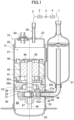
- a compressor (10) of this embodiment is a compressor (10) of oscillating piston type and is connected to a refrigerant circuit (1) as shown in FIG. 1 .
- the refrigerant circuit (1) includes the compressor (10), a radiator (2), an expansion mechanism (3), and an evaporator (4), which are connected in sequence by a refrigerant pipe (5); and performs a vapor compression refrigeration cycle by a refrigerant circulating therein.
- the expansion mechanism (3) is generally an expansion valve of which the opening degree is adjustable, but may be another element such as a capillary tube of which the opening degree is fixed.
- the compressor (10) includes a casing (20).
- the casing (20) is a closed container having a vertically long cylindrical shape and including a first end plate (22) at one end (upper end) and a second end plate (23) at the other end (lower end) of a cylindrical barrel (21) in the axial direction.
- the casing (20) houses a compression mechanism (30) that compresses a refrigerant in the refrigerant circuit (1) and an electric motor (40) of variable-speed type that drives the compression mechanism (30), where the compression mechanism (30) and the electric motor (40) are fixed to the inner peripheral surface of the barrel (21).
- the electric motor (40) is disposed in the casing (20) in which a first space (S 1) is sandwiched between the electric motor (40) and the first end plate (22), and the compression mechanism (30) is disposed in the casing (20) in which a second space (S2) is sandwiched between the compression mechanism (30) and the electric motor (40).
- the electric motor (40) includes a stator (41) and a rotor (42), both formed in a cylindrical shape.
- the stator (41) is fixed to the barrel (21) of the casing (20).
- the stator (41) includes a hollow portion where the rotor (42) is disposed.
- a drive shaft (45) is fixed to a hollow portion of the rotor (42) so as to penetrate the rotor (42), and the rotor (42) and the drive shaft (45) rotates integrally.
- the drive shaft (45) includes a main shaft portion (46) extending vertically.
- the drive shaft (45) is formed integrally with an eccentric portion (47) near a lower end of the main shaft portion (46).
- the eccentric portion (47) has a larger diameter than the main shaft portion (46).
- the eccentric portion (47) has an axis decentered by a predetermined distance with respect to the axis of the main shaft portion (46).
- a lower end portion of the main shaft portion (46) is provided with an oil supply pump (48).
- the oil supply pump (48) is immersed in lubricant oil in an oil reservoir formed at the bottom of the casing (20).
- the oil supply pump (48) pumps up lubricant oil into an oil supply path (not shown) in the drive shaft (45) along with rotation of the drive shaft (45), and then supplies the lubricant oil to each sliding portion of the compression mechanism (30).
- the compression mechanism (30) includes a cylinder (31) formed in an annular shape.
- the cylinder (31) has one axial end (upper end) to which a front head (32) is fixed and the other axial end (lower end) to which a rear head (33) is fixed.
- the cylinder (31), the front head (32), and the rear head (33) are stacked from top to bottom in order of the front head (32), the cylinder (31), and the rear head (33), and are fastened and fixed together with a plurality of bolts, for example.
- the compression mechanism (30) is what is called a single-cylinder compression mechanism including one cylinder and one piston.
- the drive shaft (45) vertically penetrates the compression mechanism (30).
- the front head (32) and the rear head (33) are provided with bearing portions (32a, 33a) that support the drive shaft (45) at both above and below the eccentric portion (47).
- the cylinder (31) has an upper end closed by the front head (32) and a lower end closed by the rear head (33).
- the internal space of the cylinder (31) forms a cylinder chamber (35).
- the cylinder (31) (cylinder chamber (35)) houses a tubular piston (34) slidably fitted to the eccentric portion (47) of the drive shaft (45).
- the piston (34) rotates eccentrically in the cylinder chamber (35).
- the piston (34) has an outer peripheral surface integrated with a blade extending radially outward from the outer peripheral surface of the piston (34). The blade is held by a bush (not shown) provided in the piston (34) and swings along with rotation of the drive shaft (45).
- a bush not shown
- the cylinder (31) has a suction port (31a) communicating with the cylinder chamber (35).
- the suction port (31a) is connected with a suction pipe (36) fixed to the barrel (21).
- the suction pipe (36) is connected with an accumulator (37) fixed to the casing (20).
- the front head (32) has a discharge port (32b) extending parallel to the axis of the drive shaft (45).
- the discharge port (32b) is opened and closed by a discharge valve (not shown).
- a muffler (38) is attached to an upper surface of the front head (32) so as to cover the discharge port (32b) and the discharge valve.
- a muffler space (38a) defined in the muffler (38) communicates with the internal space of the casing (20) through a discharge opening (38b) formed on an upper portion of the muffler (38).
- the suction pipe (36) connected to the suction port (31a) is attached to the casing (20) so that a refrigerant is sucked into the compression mechanism (30) through the accumulator (37) and the suction pipe (36).
- a discharge pipe (39) is attached to the casing (20) and penetrates the first end plate (22).
- a lower end portion of the discharge pipe (39) is open to the inside of the casing (20).
- the discharge port (32b) as a fluid outlet of the compression mechanism (30) communicates with the internal space of the casing (20) through the discharge opening (38b) of the muffler (38).
- a refrigerant discharged from the compression mechanism (30) flows out of the casing (20) through the internal space of the casing (20) and the discharge pipe (39).
- the first end plate (22) of the casing (20) is provided with a terminal (50) to which an electric wire for supplying electric power to the electric motor (40) is connected.
- the compressor of this embodiment includes: the casing (20) having a cylindrical shape and including the end plates (22, 23) at both ends; the compression mechanism (30) housed in the casing (20); and the muffler (38) disposed between the discharge port (32b) of the compression mechanism (30) and the space (second space (S2)) in the casing (20).
- the compressor (10) has a first resonance mode where the resonance frequency changes as the oil level of lubricant oil stored in the casing (20) changes and a second resonance mode where the resonance frequency does not change as the oil level of lubricant oil stored in the casing (20) changes.
- the compressor (10) includes the casing (20) and the muffler (38), each of which has a size and shape defined so that in an entire range of the first resonance mode, a resonance frequency f 1 of the first resonance mode is different from a resonance frequency f 2 of the second resonance mode.
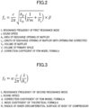
- the resonance frequency f 1 of the first resonance mode is a resonance frequency of which main parameters are a volume of the muffler and a volume of the primary space (60), and is determined by the formula shown in FIG. 2 .
- the primary space (60) is a space formed between the lower end of the electric motor (40) and the bottom surface of the casing (20) and changing in accordance with the oil level.
- the primary space is a space for removing oil accumulated in the casing (20).
- the volume of the primary space (60) includes the volume of a space below the electric motor (40) and the volume of a space below the front head.
- the resonance frequency f 1 changes as the volume of the primary space (60) changes due to change in the oil level with respect to the area of a discharge opening and the length of a discharge opening of the muffler (38) and the volume of a space (second space (S2)) below the electric motor, each determined for each compressor (10).
- the resonance frequency f 1 decreases as the volume of the primary space (60) increases due to lowering of the oil level
- the resonance frequency f 1 increases as the volume of the primary space (60) decreases due to rising of the oil level.
- the resonance frequency f 2 of the second resonance mode is a resonance frequency generated in the cross section of the casing (20), and is determined by the formula shown in FIG. 3 of which a main parameter is an inner diameter of the casing (20) in the space (second space (S2)) below the electric motor.
- a parameter of the resonance frequency f 2 of the second resonance mode is an inner diameter of part of the casing (20) forming the primary space (60).
- a value of the resonance frequency f 2 of the second resonance mode slightly changes in accordance with the state of the volume below the front head (or in accordance with the change in the oil level), and is inversely proportional to the inner diameter of the casing (20) and is substantially constant as shown in the graph of FIG. 4 .
- Ap is an area of the discharge opening (38b) of the muffler (38)
- Lp is an axial length of the discharge opening (38b) of the muffler (38) of which the opening end are corrected
- Vi is a volume of the primary space (60)
- Vm is a volume of the muffler
- ⁇ is a correction coefficient.
- the correction coefficient of an opening end is used to correct a deviation between a position of the opening end of the muffler (38) and a position of a belly of the sound wave.
- the value of the correction coefficient of an opening end is 0.3, and the correction value is 0.3d where the diameter (hydraulic diameter) of the discharge opening (38b) of the muffler (38) is d.
- the correction coefficient ⁇ is a value determined by matching a finite element method (FEM) analysis and an actual measurement.
- the resonance frequency f 1 of the first resonance mode is about 1027 Hz, where the sound speed c is 243 (m/s), assuming an example where the area Ap of the discharge opening (38b) of the muffler (38) is 5.84 ⁇ 10 -5 (m 2 ), the length Lp of the discharge opening (38b) of which the opening end is corrected is 2.83 ⁇ 10 -3 (m), the volume Vm of the muffler is 2.32 ⁇ 10 -5 (m 3 ), the volume V 1 of the primary space (60) is 1.90 ⁇ 10 -4 (m 3 ), and the correction coefficient ⁇ is 0.84.
- the correction coefficient ⁇ is a value determined by matching a FEM analysis and a actual measurement
- the mode coefficient ⁇ is a constant determined by the second resonance mode
- R 1 is a radius of the inner circumferential surface of the body.
- the resonance frequency f 2 of the second resonance mode is about 1154 Hz
- the correction coefficient ⁇ is 0.73
- the mode coefficient ⁇ is 1.84
- the radius R1 is 4.5 ⁇ 10 -2 (m)
- the sound speed c is 243 (m/s).
- the resonance frequency f 1 of the first resonance mode is about 1160 Hz, where, for example, the area Ap of the discharge opening of the muffler is 4.75 ⁇ 10 -5 (m 2 ), the length Lp of the discharge opening of which the opening end is corrected is 2.65 ⁇ 10 -3 (m), the volume Vm of the muffler is 1.55 ⁇ 10 -5 (m 3 ), the volume V 1 of the primary space (60) is 1.56 ⁇ 10 -4 (m 3 ), the correction coefficient ⁇ is 0.84, and the sound speed c is 243 (m/s).
- the resonance frequency f 2 of the second resonance mode is about 1154 Hz similarly to the above example, where the correction coefficient ⁇ is 0.73, the mode coefficient ⁇ is 1.84, the radius R 1 is 4.5 ⁇ 10 -2 (m) similarly to the above example, and the sound speed c is 243 (m/s).
- this embodiment exhibits a large difference between the resonance frequency f 1 of the first resonance mode and the resonance frequency f 2 of the second resonance mode, while the typical compressor exhibits a small difference between the resonance frequency f 1 of the first resonance mode and the resonance frequency f 2 of the second resonance mode.
- the typical compressor if the resonance frequency f 1 of the first resonance mode fluctuates, the resonance frequencies of the two resonance modes are likely to match each other.
- the resonance frequency f 1 of the first resonance mode and the resonance frequency f 2 of the second resonance mode match each other at any point, the two resonance modes overlapping each other causes amplification of the sound, thereby causing noise increase.
- the size of the casing (20) or the muffler (38) is set so that the resonance frequency f 1 of the first resonance mode is different from the resonance frequency f 2 of the second resonance mode in the entire range of the first resonance mode, and thus the two resonance modes do not overlap each other.
- the size of the casing (20) or the muffler (38) is determined so that as shown in FIG. 5 the resonance frequency f 1 of the first resonance mode is lower than the resonance frequency f 2 of the second resonance mode at the oil level reached by the amount of oil initially supplied into the casing (20).
- a diameter of the discharge opening of the muffler, the number of discharge openings of the muffler, an area of the discharge opening of the muffler, a plate thickness of the muffler, a volume of the muffler space (38a), an inner diameter of the barrel (21), a volume of the primary space (60), and the like are determined so that f 1 ⁇ f 2 holds true as described in the above embodiment. If the parameters shown in the formulas of FIGS. 2 and 3 are set so that f 1 ⁇ f 2 holds true at the oil level reached by the amount of oil initially supplied, f 1 ⁇ f 2 holds true at all times during an operation of the compressor (10). As a result, at all times during the operation, the resonance frequency f 1 of the first resonance mode and the resonance frequency f 2 of the second resonance mode do not match each other at any point, and thus noise increase caused by the two resonance modes overlapping each other can be reduced.
- a compressor When operating at a high speed (e.g., where the rotational speed N (rps) during a steady operation is 120 ⁇ N), a compressor undergoes an oil loss such that there is significant change in the oil level reached by the amount of oil initially supplied.
- N rotational speed
- the compressor (10) that do not allow the two resonance modes to overlap each other is more useful in one preferred embodiment.
- a typical compressor operating at a high speed causes the oil level to lower, thereby allowing the two resonance modes to overlap each other, but the compressor of this embodiment do not allow them to overlap each other even when the oil level lowers, thereby easily operating at a high speed.
- the compressor (10) operating at a high speed tends to allow the casing (20) to discharge a larger amount of oil so that the oil level lowers.
- the casing (20) is downsized and has a smaller diameter, the oil level significantly fluctuates as the amount of oil changes.
- the resonance frequency of the first resonance mode and the resonance frequency of the second resonance mode are likely to match each other.
- the size and shape of the casing (20) or the muffler (38) are set so that the resonance frequency of the first resonance mode is different from the resonance frequency of the second resonance mode. Accordingly, even if the oil level fluctuates, the resonance frequencies of the two resonance modes do not match each other. Thus, noise increase caused by the two resonance modes overlapping each other can be reduced. In addition, even if the oil level easily fluctuates by the compressor (10) being downsized and operated at a high speed, the two resonance modes do not overlap each other, and thus noise increase can be reduced. This embodiment has a great advantage in reducing the noise even if the compressor is not downsized and operated at a high speed.
- the sizes and shapes of parts such as a diameter of a discharge opening of a muffler, the number of discharge openings of the muffler, an area of the discharge opening of the muffler, a plate thickness of the muffler, a volume of a muffler space (38a), an inner diameter of a barrel (21), a volume of a primary space (60), and the like are determined so that with no lubricant oil being stored in a casing (20), a resonance frequency of the first resonance mode is higher than a resonance frequency of the second resonance mode, as shown in FIG. 6 . If the parameters shown in the formulas of FIGS.
- the second embodiment relates to an air conditioner including a refrigerant circuit (1).
- a compressor (10) of the air conditioner includes: a casing (20) having a cylindrical shape and including end plates (22, 23) at both ends; a compression mechanism (30) housed in a casing (20); and a muffler (38) disposed between a fluid outlet (32b) of the compression mechanism (30) and a space in the casing (20).
- the compressor (10) has a first resonance mode where the resonance frequency changes as the oil level of lubricant oil stored in the casing (20) changes and a second resonance mode where the resonance frequency does not change as the oil level of lubricant oil stored in the casing (20) changes.
- the amount of oil and the length of pipe in the refrigerant circuit (1) are determined so that the resonance frequency of the first resonance mode is lower than the resonance frequency of the second resonance mode at the oil level at which lubricant oil in the refrigerant circuit (1) is collected in the compressor (10).
- the sizes of the casing (20) and the muffler (38) of the compressor (10) are not necessarily set so that the resonance frequency of the first resonance mode is different from the resonance frequency of the second resonance mode, but the use of the compressor of the first embodiment is not excluded.
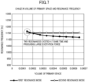
- the resonance frequency f 1 of the first resonance mode is lower than the resonance frequency f 2 of the second resonance mode when the oil level of lubricant oil is at the highest one, and thus similarly to the example shown in FIG. 5 , the resonance frequencies f 1 and f 2 do not match each other at any point during the operation. If as shown in FIG. 7 the resonance frequencies f 1 and f 2 of the two resonance modes match each other at any point, the noise increases, but according to the second embodiment, noise increase caused by the resonance frequencies f 1 and f 2 of the two resonance modes overlapping each other can be reduced.
- an air conditioner of a first variation includes a refrigerant circuit (1) including a compressor having a first resonance mode and a second resonance mode.
- the air conditioner operates to control the oil level of a compressor (10) so that the resonance frequency of the first resonance mode is lower than the resonance frequency of the second resonance mode at all times during a steady operation in the entire operation range.
- an oil return circuit (6) in the refrigerant circuit (1) is used to adjust the amount of oil returned to the compressor (10).
- the compressor (10) is provided with an oil level gauge (not shown) for detecting the oil level.
- the oil return circuit (6) includes an oil separator (7) connected to the discharge side of the compressor (10) and includes an oil return pipe (7a) connected to a suction pipe (37a) provided between an accumulator (37) and the compressor (10).
- the oil return pipe (7a) is provided with an oil return valve (7b).
- the oil return valve (7b) may be an on-off valve adjustable between two positions, i.e., a fully closed position and a fully open position, or may be an opening degree control valve adjustable to any opening degree.
- the rotational speed of the compressor (10) is increased to increase the amount of refrigerant circulated, and the oil return valve (7b) is opened to collect the oil in the refrigerant circuit (1).
- the amount of oil loss (the amount of oil flowing out of the compressor (10)) increases, and thus, in general, the rotational speed is set to a medium speed in order to reduce the oil loss.
- the differential pressure in the refrigerant circuit increases, the amount of oil loss increases, and thus, in general, the oil return operation is performed with a low load (low differential pressure).
- the oil level gauge detects that the oil level of the compressor (10) lowers, the oil return operation is performed at a medium speed with a low load in order to secure the oil level. Accordingly, the oil level rises. In contrast, an operation at a high speed with a high differential pressure causes increase in the amount of oil loss, and thus an operation at a high speed with a high differential pressure is performed in order to decrease the oil level.
- the resonance frequencies f 1 and f 2 of the two resonance modes do not match each other at any point, and thus noise increase caused by the resonance frequencies of the two resonance modes overlapping each other can be reduced.
- an air conditioner of a second variation includes a refrigerant circuit (1) including a compressor having a first resonance mode and a second resonance mode.
- the air conditioner operates to control the oil level of a compressor (10) so that the resonance frequency of the first resonance mode is higher than the resonance frequency of the second resonance mode at all times during a steady operation in the entire operation range.
- the resonance frequencies f 1 and f 2 of the two resonance modes do not match each other at any point, and thus similarly to the first variation, noise increase caused by the resonance frequencies of the two resonance modes overlapping each other can be reduced.
- an air conditioner of a third variation includes a refrigerant circuit (1) including a compressor having a first resonance mode and a second resonance mode.
- the air conditioner operates to control the rotational speed of the compressor (10) to avoid a point at which the resonance frequencies f 1 and fz of the first resonance mode and the second resonance mode match each other, thereby controlling the resonance frequency of the first resonance mode.
- the air conditioner operates to adjust the rotational speed of the compressor (10) in order to adjust the oil level so that the resonance frequency f 1 of the first resonance mode do not match the resonance frequency f 2 of the second resonance mode.
- the operation of adjusting the oil level in the second embodiment can be performed by avoiding an operation of the compressor (10) and not performing a steady operation at a point at which the resonance frequencies of the first resonance mode and the second resonance mode match each other.
- the resonance frequencies f 1 and f 2 of the two resonance modes do not match each other at any point, and thus similarly to the first and second variations, noise increase caused by the resonance frequencies of the two resonance modes overlapping each other can be reduced.
- the above embodiments assume that the compressor (10) is downsized and rotated at a high speed, but the configuration of the present disclosure is useful in reducing the noise not only when a compressor is downsized and rotated at a high speed but also when a compressor in a typical size is rotated at a normal speed, when a compressor in a normal size is rotated at a high speed, and when a compressor in a still smaller size is rotated at a normal speed.
- the numerical values in the embodiments are not limited to themselves.
- the present disclosure is useful for a compressor and an air conditioner.
Landscapes
- Engineering & Computer Science (AREA)
- Mechanical Engineering (AREA)
- General Engineering & Computer Science (AREA)
- Chemical & Material Sciences (AREA)
- Combustion & Propulsion (AREA)
- Compressor (AREA)
- Applications Or Details Of Rotary Compressors (AREA)
Applications Claiming Priority (2)
| Application Number | Priority Date | Filing Date | Title |
|---|---|---|---|
| JP2022059440 | 2022-03-31 | ||
| PCT/JP2023/011559 WO2023190051A1 (fr) | 2022-03-31 | 2023-03-23 | Compresseur et climatiseur |
Publications (2)
| Publication Number | Publication Date |
|---|---|
| EP4455485A1 true EP4455485A1 (fr) | 2024-10-30 |
| EP4455485A4 EP4455485A4 (fr) | 2025-07-30 |
Family
ID=88202073
Family Applications (1)
| Application Number | Title | Priority Date | Filing Date |
|---|---|---|---|
| EP23780062.8A Pending EP4455485A4 (fr) | 2022-03-31 | 2023-03-23 | Compresseur et climatiseur |
Country Status (6)
| Country | Link |
|---|---|
| US (1) | US20240410601A1 (fr) |
| EP (1) | EP4455485A4 (fr) |
| JP (1) | JP7381975B2 (fr) |
| CN (1) | CN118575000A (fr) |
| AU (1) | AU2023242477B2 (fr) |
| WO (1) | WO2023190051A1 (fr) |
Family Cites Families (8)
| Publication number | Priority date | Publication date | Assignee | Title |
|---|---|---|---|---|
| JPS5827047Y2 (ja) | 1978-07-19 | 1983-06-11 | 松下電器産業株式会社 | 密閉型圧縮機の消音装置 |
| JPS5679683U (fr) * | 1979-11-22 | 1981-06-27 | ||
| JPH11141489A (ja) * | 1997-10-31 | 1999-05-25 | Toshiba Corp | ロータリコンプレッサ |
| JP2005113867A (ja) * | 2003-10-10 | 2005-04-28 | Matsushita Electric Ind Co Ltd | 密閉型圧縮機 |
| CN104379937B (zh) * | 2012-05-09 | 2017-12-22 | 三菱电机株式会社 | 密闭型压缩机和热泵装置 |
| JP6147605B2 (ja) * | 2013-08-02 | 2017-06-14 | 三菱重工業株式会社 | 圧縮機 |
| JP2016070229A (ja) * | 2014-09-30 | 2016-05-09 | ダイキン工業株式会社 | 圧縮機 |
| JP2018096272A (ja) * | 2016-12-13 | 2018-06-21 | ダイキン工業株式会社 | ケーシングに固定された圧縮機構を備える圧縮機 |
-
2023
- 2023-03-23 AU AU2023242477A patent/AU2023242477B2/en active Active
- 2023-03-23 CN CN202380017299.9A patent/CN118575000A/zh active Pending
- 2023-03-23 JP JP2023046141A patent/JP7381975B2/ja active Active
- 2023-03-23 EP EP23780062.8A patent/EP4455485A4/fr active Pending
- 2023-03-23 WO PCT/JP2023/011559 patent/WO2023190051A1/fr not_active Ceased
-
2024
- 2024-08-22 US US18/812,744 patent/US20240410601A1/en active Pending
Also Published As
| Publication number | Publication date |
|---|---|
| AU2023242477A1 (en) | 2024-11-14 |
| JP2023152858A (ja) | 2023-10-17 |
| WO2023190051A1 (fr) | 2023-10-05 |
| CN118575000A (zh) | 2024-08-30 |
| JP7381975B2 (ja) | 2023-11-16 |
| US20240410601A1 (en) | 2024-12-12 |
| AU2023242477B2 (en) | 2026-01-29 |
| EP4455485A4 (fr) | 2025-07-30 |
Similar Documents
| Publication | Publication Date | Title |
|---|---|---|
| US9512842B2 (en) | Rotary compressor | |
| US8978826B2 (en) | Compressor | |
| US12421967B2 (en) | Rotary compressor and refrigeration device | |
| EP3343065A1 (fr) | Dispositif de réglage d'inertie et compresseur rotatif | |
| EP4455485A1 (fr) | Compresseur et climatiseur | |
| CN103821722A (zh) | 压缩机 | |
| EP4411136A1 (fr) | Unité de compresseur | |
| EP3450763A1 (fr) | Compresseur à vis | |
| EP3636929B1 (fr) | Compresseur rotatif | |
| EP4455484B1 (fr) | Compresseur rotatif et climatiseur | |
| EP2039936A1 (fr) | Compresseur à spirales | |
| JP6841272B2 (ja) | 回転式圧縮機 | |
| US20120160610A1 (en) | Lubricant supply tube for compressors | |
| JP2014118862A (ja) | 回転式圧縮機 | |
| EP4477888A1 (fr) | Compresseur et dispositif de réfrigération | |
| US11067078B2 (en) | Scroll compressor having single discharge port open at starting end of fixed-side wrap | |
| JP5361682B2 (ja) | 圧縮機 | |
| KR101406509B1 (ko) | 오일 회수 부재 및 이를 적용한 전동기구와 압축기 | |
| WO2017141343A1 (fr) | Compresseur | |
| EP3211233A1 (fr) | Compresseur hermétique à double cylindre | |
| JPH11125189A (ja) | 流体圧縮機 | |
| JPH11132174A (ja) | ヘリカルコンプレッサ | |
| JP2016132999A (ja) | ロータリ圧縮機 |
Legal Events
| Date | Code | Title | Description |
|---|---|---|---|
| STAA | Information on the status of an ep patent application or granted ep patent |
Free format text: STATUS: THE INTERNATIONAL PUBLICATION HAS BEEN MADE |
|
| PUAI | Public reference made under article 153(3) epc to a published international application that has entered the european phase |
Free format text: ORIGINAL CODE: 0009012 |
|
| STAA | Information on the status of an ep patent application or granted ep patent |
Free format text: STATUS: REQUEST FOR EXAMINATION WAS MADE |
|
| 17P | Request for examination filed |
Effective date: 20240724 |
|
| AK | Designated contracting states |
Kind code of ref document: A1 Designated state(s): AL AT BE BG CH CY CZ DE DK EE ES FI FR GB GR HR HU IE IS IT LI LT LU LV MC ME MK MT NL NO PL PT RO RS SE SI SK SM TR |
|
| P01 | Opt-out of the competence of the unified patent court (upc) registered |
Free format text: CASE NUMBER: APP_959/2025 Effective date: 20250108 |
|
| DAV | Request for validation of the european patent (deleted) | ||
| DAX | Request for extension of the european patent (deleted) | ||
| A4 | Supplementary search report drawn up and despatched |
Effective date: 20250630 |
|
| RIC1 | Information provided on ipc code assigned before grant |
Ipc: F04C 29/06 20060101AFI20250624BHEP Ipc: F04B 39/00 20060101ALI20250624BHEP Ipc: F04B 35/04 20060101ALI20250624BHEP Ipc: F04C 23/00 20060101ALI20250624BHEP Ipc: F04B 39/02 20060101ALI20250624BHEP |
|
| STAA | Information on the status of an ep patent application or granted ep patent |
Free format text: STATUS: EXAMINATION IS IN PROGRESS |