EP4455497A1 - Stufenlos längenverstellbare pleuelstange und verfahren zur montage der verstellstange - Google Patents
Stufenlos längenverstellbare pleuelstange und verfahren zur montage der verstellstange Download PDFInfo
- Publication number
- EP4455497A1 EP4455497A1 EP24168548.6A EP24168548A EP4455497A1 EP 4455497 A1 EP4455497 A1 EP 4455497A1 EP 24168548 A EP24168548 A EP 24168548A EP 4455497 A1 EP4455497 A1 EP 4455497A1
- Authority
- EP
- European Patent Office
- Prior art keywords
- connecting rod
- yoke
- intermediate part
- pivot axis
- pivot
- Prior art date
- Legal status (The legal status is an assumption and is not a legal conclusion. Google has not performed a legal analysis and makes no representation as to the accuracy of the status listed.)
- Pending
Links
Images


Classifications
-
- F—MECHANICAL ENGINEERING; LIGHTING; HEATING; WEAPONS; BLASTING
- F16—ENGINEERING ELEMENTS AND UNITS; GENERAL MEASURES FOR PRODUCING AND MAINTAINING EFFECTIVE FUNCTIONING OF MACHINES OR INSTALLATIONS; THERMAL INSULATION IN GENERAL
- F16C—SHAFTS; FLEXIBLE SHAFTS; ELEMENTS OR CRANKSHAFT MECHANISMS; ROTARY BODIES OTHER THAN GEARING ELEMENTS; BEARINGS
- F16C7/00—Connecting-rods or like links pivoted at both ends; Construction of connecting-rod heads
- F16C7/06—Adjustable connecting-rods
-
- A—HUMAN NECESSITIES
- A61—MEDICAL OR VETERINARY SCIENCE; HYGIENE
- A61B—DIAGNOSIS; SURGERY; IDENTIFICATION
- A61B17/00—Surgical instruments, devices or methods
- A61B17/56—Surgical instruments or methods for treatment of bones or joints; Devices specially adapted therefor
- A61B17/58—Surgical instruments or methods for treatment of bones or joints; Devices specially adapted therefor for osteosynthesis, e.g. bone plates, screws or setting implements
- A61B17/68—Internal fixation devices, including fasteners and spinal fixators, even if a part thereof projects from the skin
- A61B17/70—Spinal positioners or stabilisers, e.g. stabilisers comprising fluid filler in an implant
- A61B17/7001—Screws or hooks combined with longitudinal elements which do not contact vertebrae
- A61B17/7002—Longitudinal elements, e.g. rods
-
- A—HUMAN NECESSITIES
- A61—MEDICAL OR VETERINARY SCIENCE; HYGIENE
- A61B—DIAGNOSIS; SURGERY; IDENTIFICATION
- A61B17/00—Surgical instruments, devices or methods
- A61B17/56—Surgical instruments or methods for treatment of bones or joints; Devices specially adapted therefor
- A61B17/58—Surgical instruments or methods for treatment of bones or joints; Devices specially adapted therefor for osteosynthesis, e.g. bone plates, screws or setting implements
- A61B17/68—Internal fixation devices, including fasteners and spinal fixators, even if a part thereof projects from the skin
- A61B17/70—Spinal positioners or stabilisers, e.g. stabilisers comprising fluid filler in an implant
- A61B17/7001—Screws or hooks combined with longitudinal elements which do not contact vertebrae
- A61B17/7032—Screws or hooks with U-shaped head or back through which longitudinal rods pass
-
- A—HUMAN NECESSITIES
- A61—MEDICAL OR VETERINARY SCIENCE; HYGIENE
- A61B—DIAGNOSIS; SURGERY; IDENTIFICATION
- A61B17/00—Surgical instruments, devices or methods
- A61B17/56—Surgical instruments or methods for treatment of bones or joints; Devices specially adapted therefor
- A61B17/58—Surgical instruments or methods for treatment of bones or joints; Devices specially adapted therefor for osteosynthesis, e.g. bone plates, screws or setting implements
- A61B17/68—Internal fixation devices, including fasteners and spinal fixators, even if a part thereof projects from the skin
- A61B17/70—Spinal positioners or stabilisers, e.g. stabilisers comprising fluid filler in an implant
- A61B17/7001—Screws or hooks combined with longitudinal elements which do not contact vertebrae
- A61B17/7035—Screws or hooks, wherein a rod-clamping part and a bone-anchoring part can pivot relative to each other
- A61B17/7037—Screws or hooks, wherein a rod-clamping part and a bone-anchoring part can pivot relative to each other wherein pivoting is blocked when the rod is clamped
Definitions
- the present invention relates to a continuously length-adjustable connecting rod and a method of mounting the adjustable connecting rod.
- a connecting rod is an elongated part, such as a bar, making an articulated or non-articulated connection between two elements.
- the length of the connecting rod is adapted to the distance between the two elements.
- adjustable connecting rods that allow their length to be adjusted in order to adapt it to said distance between the two elements.
- These adjustable connecting rods have a yoke connected to a connecting rod body by screwing a threaded rod into a bore located at one end of the connecting rod body.
- the threaded rod in order to adjust the length of the yoke so that it can be attached to the element for which it is intended, the threaded rod must turn half turns so that the yoke is aligned with said element.
- the present invention aims to overcome the drawbacks of existing adjustable connecting rods.
- the length of the adjustable connecting rod can be continuously adjusted while maintaining an angular position of the yoke while the helical linkage is set in motion.
- the adjustment device includes a locking device configured to block rotation of the intermediate piece relative to the connecting rod body after the yoke has reached a desired position allowing attachment of the yoke to the first member.
- the pivot connection connects the intermediate part to the connecting rod body and the helical connection connects the intermediate part to the yoke.
- the pivot connection connects the intermediate part to the yoke and the helical connection connects the intermediate part to the connecting rod body.
- the invention also relates to a method of mounting the connecting rod to a first element and to a second element.
- the method comprises a step of fixing the second end of the connecting rod body to the second element.
- the method further comprises a locking step by the locking device to block the rotation of the intermediate part relative to the connecting rod body after the yoke has reached a desired position allowing the yoke to be fixed to the first element.
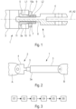
- adjustable connecting rod 1 The embodiments and variants of the adjustable connecting rod 1 are shown in the figure 1 and the Figures 4 to 7 .
- the adjustable connecting rod 1 is adjustable in length. It extends along a longitudinal axis A1.
- the adjustable connecting rod comprises an adjustment device 2 configured to adjust the length of the adjustable connecting rod 1 and to articulate the adjustable connecting rod 1 to a first element A.
- the adjustable connecting rod 1 also comprises a connecting rod body 3 having a first end 3a comprising the adjustment device 2 and a second end 3b intended to connect the adjustable connecting rod 1 to a second element B.
- the second end 3b is intended to connect the adjustable connecting rod 1 to the second element B according to two configurations.
- the second end 3b is intended to articulate the adjustable connecting rod 1 to the second element B.
- the second end 3b is securely connected to the second element B.
- the second element B can comprise the connecting rod body 3.
- the first element A and the second element B can correspond to two separate systems which are intended to be linked together by the adjustable connecting rod 1 ( figure 2 ).
- the adjustment device 2 comprises at least one fixing yoke 4 intended to fix the adjustable connecting rod 1 to the first element A and an intermediate piece 5, 6 connecting the yoke 4 to the connecting rod body 3 between a pivot connection L1 and a helical connection L2.
- the helical connection L2 is configured to allow a translation of the yoke 4 along a pivot axis A2 parallel to the longitudinal axis A1 of the adjustable connecting rod 1 when the intermediate part 5, 6 is rotated by a user around the pivot axis A2.
- the pivot link L1 is configured to allow the maintenance of an angular position of the yoke 4 around the pivot axis A2 when the intermediate part 5, 6 is rotated around the pivot axis A2.
- the user can maintain the angular position of the yoke 4 so that it remains aligned with the first element A when the intermediate part 5, 6 is rotating around the pivot axis A2.
- the adjustment device 2 may also comprise a locking device 7 configured to block the rotation of the intermediate part 5, 6 relative to the connecting rod body 3 after the yoke 4 has reached a desired position allowing the yoke 4 to be fixed to the first element A.
- the pivot connection L1 connects the intermediate part 5 to the connecting rod body 3.
- the helical connection L2 connects the intermediate piece 5 to the yoke 4.
- the yoke 4 comprises a threaded rod 8 having a longitudinal axis coincident with the pivot axis A2.
- the intermediate piece 5 has a generally cylindrical shape having a coincident axis of revolution with the pivot axis A2.
- the intermediate part 5 further having a tapped through bore 9.
- the tapped through bore 9 has an axis of revolution coincident with the pivot axis A2.
- the threaded rod 8 of the yoke 4 is screwed into the tapped through bore 9 of the intermediate part 5 to form the helical connection L2.
- the connecting rod body 3 comprises a smooth bore 10 having an axis of revolution coincident with the pivot axis A2.
- the smooth bore 10 has a first end 10a opening onto the first end 3a of the connecting rod body 3.
- the intermediate part 5 has a smooth external surface. The intermediate part 5 is inserted into the smooth bore 10 to form the pivot connection L1. A rotation of the intermediate part 5 relative to the connecting rod body 3 by a user is likely to cause a translation of the yoke 4 along the pivot axis A2 when the yoke 4 is blocked in rotation about the pivot axis A2 by the user.
- the adjustment device 2 further comprises a locking device 11 configured to lock the intermediate part 5 in translation parallel to the pivot axis A2.
- This locking device makes it possible to maintain the pivot connection L1 between the intermediate part 5 and the connecting rod body 30a so that it does not become a sliding pivot connection.
- the locking device 11 may comprise the locking device 7, as shown in FIG. figure 1 .
- FIG. 4 represents a first variant of the first embodiment of the adjustable connecting rod 1.
- the connecting rod body 3 comprises a slot 12 passing through the connecting rod body 3 perpendicular to the pivot axis A2.
- the smooth bore 10 has a second end 10b opening into the slot 12.
- the smooth bore 10 is a through bore extending between, on the one hand, its first end 10a opening onto the first end 3a of the connecting rod body 3 and, on the other hand, its second end 10b opening into the slot 12.
- the intermediate piece 5 has a circumferential shoulder 13 on the external surface of the intermediate piece 5.
- the intermediate piece 5 is placed in the smooth bore 10 so that the circumferential shoulder 13 is located in the lumen 12.
- the locking device 11 comprises a plate 14 and a locking nut 16.
- the plate 14 is configured to block the intermediate part 5 in translation towards the first end 3a of the connecting rod body 3.
- the plate 14 has an orifice 15 through which the intermediate part 5 is inserted.
- the plate 14 is arranged between the second end 10b of the smooth bore 10 and the circumferential shoulder 13.
- the orifice 15 of the plate 14 has a diameter strictly less than the diameter of the circumferential shoulder 13.
- the plate 14 can take different shapes.
- the plate 14 has at least one surface which is adapted so that it matches the internal surface of the slot 12 against which the plate 14 is pressed.
- the plate 14 has a half-cylinder shape having a curved surface and a flat surface.
- the curved surface is adapted so that it matches the internal surface of the slot 12 against which the plate 14 is pressed.
- the flat surface is adapted to receive the circumferential shoulder 13 of the intermediate piece 5.
- the locking nut 16 is configured to lock the intermediate piece 5 in translation towards the second end 3b of the connecting rod body 3.
- the locking nut 16 is screwed to a threaded portion on the external surface of the intermediate piece 5 against the first end 3a of the connecting rod body 3.
- the intermediate part 5 may comprise a longitudinal groove 24.
- the locking nut 16 may correspond to a notched nut.
- the locking device 7 comprises a brake washer 25 assembled to the intermediate part 5 between the locking nut 16 and the first end 10a of the smooth bore 10.
- the brake washer 25 comprises external tabs 26 moving away from the brake washer 25 and an internal tooth 27 inserting into the longitudinal groove 24 of the intermediate part 5. The rotation of the intermediate part 5 relative to the connecting rod body 3 is blocked by pressing the brake washer 25 against the first end 10a of the smooth bore 10 by screwing the locking nut 16 to the threaded portion of the intermediate part 5 in the direction of the connecting rod body 3 and by folding the tabs 26 of the brake washer 25 into notches 28 of the locking nut 16.
- FIG. 5 represents a second variant of the first embodiment of the adjustable connecting rod 1.
- the intermediate piece 5 has a circumferential shoulder 17 on its external surface.
- the locking device 11 comprises a U-shaped part 18 and a locking nut 20.
- the U-shaped part 18 is interposed between the circumferential shoulder 17 and the locking nut 20.
- the U-shaped part 18 is configured to block the intermediate part 5 in translation towards the first end 3a of the connecting rod body 3.
- the U-shaped part 18 has a U-shaped profile having two parallel sides 18a, 18b.
- the two sides 18a, 18b correspond to the two free ends of the U which is the shape of the profile of the U-shaped part.
- the two sides 18a, 18b of the U-shaped part 18 are fixed to the first end 3a of the connecting rod body 3.
- the free ends of the U are directed towards the second end 3b of the connecting rod body 3.
- the U-shaped part 18 has an opening 19 through which the intermediate part 5 is inserted.
- the circumferential shoulder 17 is located between the U-shaped part 18 and the first end 3a of the connecting rod body 3.
- the opening 19 of the U-shaped part 18 has a diameter strictly less than the diameter of the circumferential shoulder 17 of the intermediate part 5, so that the U-shaped part 18 retains the intermediate part 5.
- the locking nut 20 is configured to lock the intermediate part 5 in translation towards the second end 3b of the connecting rod body 3.
- the locking nut 20 is screwed to a threaded portion on the external surface of the intermediate part 5 against the U-shaped part 18.
- the intermediate part 5 may comprise a longitudinal groove 24.
- the locking nut 20 may correspond to a first lock-wire nut having lock-wire holes 29.
- the locking device 11 comprises a first lock washer 30 assembled to the intermediate part 5 between the first lock nut 20 and the U-shaped part 18.
- the first lock washer 30 comprises a tab having a lock wire hole and an internal tooth inserting into the longitudinal groove 24 of the intermediate piece 5.
- the rotation of the intermediate part 5 relative to the connecting rod body 3 can be blocked by pressing the first lock washer 30 against the U-shaped part 18 by screwing the first lock nut 20 and by a wire passing through lock holes 29 of the first lock nut 20 and through the lock hole of the first lock washer.
- FIG. 6 represents a third variant of the first embodiment of the adjustable connecting rod 1.
- the intermediate part 5 has a circumferential groove 21 on its external surface.
- the locking device 11 comprises at least one retaining rod 22.
- the retaining rod(s) 22 pass at least partially through the connecting rod body 3 perpendicular to the pivot axis A2.
- the retaining rod(s) 22 are partially inserted into the circumferential groove 21 of the intermediate part 5 parallel to the circumferential groove 21.
- the retaining rod(s) 22 block the translation of the intermediate part 5 parallel to the pivot axis A2.
- the locking device 11 comprises two retaining rods 22 inserted into the connecting rod body 3 on either side of the intermediate part 5.
- the retaining rod(s) 22 may comprise an external surface having a smooth portion and a threaded portion. The threaded portion may be located at their free end.
- the retaining rod(s) 22 are screwed into the connecting rod body 3 at their free end at the threaded portion.
- the smooth portion of the retaining rod(s) 22 is then partially received in the circumferential groove 21.
- the intermediate piece 5 can comprise a longitudinal groove 24.
- the locking device 11 comprises a first lock nut 23 screwed to a threaded section of the intermediate part 5 and a first lock washer 30 assembled to the intermediate part 5 between the first lock nut 23 and the first end 10a of the smooth bore 10.
- the first washer with a lock wire 30 comprises a tab 31 having a lock wire hole 32 and an internal tooth inserting into the longitudinal groove 24 of the intermediate piece 5.
- the rotation of the intermediate part 5 relative to the connecting rod body 3 can be blocked by pressing the first lock washer 30 against the first end 10a of the smooth bore 10 by screwing the first lock nut 23 and by a wire passing through lock holes 32 of the first lock nut 23 and through the lock hole 32 of the first lock washer 30.
- the locking device 11 may further comprise a locking nut 34 screwed to the threaded rod 8 of the yoke 4 to block the translation of the threaded rod 8 of the yoke 4 relative to the intermediate part 5.
- the locking nut 16 corresponds to a second lock nut.
- the threaded rod 8 of the yoke 4 comprises a longitudinal groove 33.
- the locking device 11 may also comprise a second lock washer 35 assembled to the threaded rod 8 of the yoke 4 between the second lock nut 16 and the intermediate part 5.
- the second lock washer 35 comprises a tab having a lock hole and an internal tooth inserted into the longitudinal groove 33 of the threaded rod 8 of the yoke 4. The rotation of the intermediate part 5 relative to the connecting rod body 3 is blocked by pressing the second lock washer 35 against the intermediate part 5 by screwing the second lock nut 16 and by passing a wire through the lock holes of the second lock nut 16 and through the lock hole of the second lock washer 35.
- the intermediate part 5 may comprise at least two flats 45 on its external surface, arranged at 180° relative to each other. These flats 45 allow the user to manually or using a tool operate the intermediate part 5 so that it rotates around the pivot axis A2.
- the tool may correspond to an adjustable wrench, an English wrench, a multi-grip wrench or any other type of suitable tool.
- the pivot connection L1 connects the intermediate part 6 to the yoke 4.
- the helical connection L2 connects the intermediate part 6 to the connecting rod body 3.
- the intermediate part 6 corresponds to a threaded rod 6 having an axis of revolution coincident with the pivot axis A2.
- the yoke 4 comprises an opening 36 having a center coincident with the pivot axis A2.
- the threaded rod 6 has a first end 6a passing through the opening 36 of the yoke 4 to form the pivot connection L1.
- the connecting rod body 3 has a tapped bore 37 having an axis of revolution coincident with the pivot axis A2.
- the threaded rod 6 has a second end 6b screwed into the tapped bore 37 to form the helical connection L2.
- the tapped bore 37 may correspond to a smooth bore in which a tapped sleeve is inserted.
- the adjustment device 2 further comprises a locking device 11 configured to lock the yoke 4 in translation parallel to the pivot axis A2 along the threaded rod 6.
- a rotation of the threaded rod 6 relative to the connecting rod body 3 by a user is likely to cause a translation of the threaded rod 6 and the yoke 4 along the pivot axis A2 when the yoke 4 is blocked in rotation about the pivot axis A2 by the user.
- the locking device 11 comprises a first locking nut 38 and a circumferential shoulder 39.
- the first locking nut 38 is screwed to the first end 6a of the threaded rod 6 so that the yoke 4 is blocked in translation towards the first end 6a of the threaded rod 6.
- the circumferential shoulder 39 corresponds to a circumferential shoulder of the threaded rod 6 so that the yoke 4 is blocked in translation towards the second end 6b of the threaded rod 6.
- the threaded rod 6 comprises a longitudinal groove 40.
- the first locking nut 38 corresponds to a notched nut.
- the locking device comprises a first brake washer 41, a second brake washer 42, a third brake washer 44 and a second locking nut 43.
- the first brake washer 41 is mounted to the threaded rod 6 between the yoke 4 and the slotted nut 38.
- the first brake washer 41 has external tabs extending away from the first brake washer 41 and an internal tooth fitting into the longitudinal groove 40 of the threaded rod 6.
- the second brake washer 42 is mounted to the threaded rod 6 between the yoke 4 and the circumferential shoulder 39.
- the second brake washer 42 has external tabs extending away from the second brake washer 42 and an internal tooth inserting into the longitudinal groove 40 of the threaded rod 6.
- the second locking nut 43 is screwed to the second end 6b of the threaded rod 6.
- the third brake washer 44 is mounted to the threaded rod 6 between the second lock nut 43 and the first end 3b of the connecting rod body 3.
- the third brake washer 44 has external tabs extending away from the third brake washer 44 and an internal tooth fitting into the longitudinal groove 40 of the threaded rod 6.
- the circumferential shoulder 39 of the threaded rod 6 may comprise at least two flats on its external surface, arranged at 180° relative to each other. These flats allow the user to manually or using a tool operate the threaded rod 6 so that it rotates about the pivot axis A2.
- the tool may correspond to an adjustable wrench, an English wrench, a multi-grip wrench or any other type of suitable tool.
- the invention also relates to a method of mounting the adjustable connecting rod 1 to a first element A and to a second element B ( figure 3 ).
- the intermediate part 5, 6 is rotated relative to the connecting rod body 3 by a user to cause a translation of the yoke 4 parallel to the pivot axis A2 until the yoke 4 reaches a desired position allowing the yoke 4 to be fixed to the first element A.
- the pivot connection L1 is set in motion by the rotation of the intermediate part 5, 6 while the angular position of the yoke 4 is maintained.
- Alignment step E2 corresponds to placing the adjustable connecting rod 1 between the two elements A and B so that the longitudinal axis A1 of the adjustable connecting rod 1 is as close as possible to its final position. Its final position corresponds to the position of the longitudinal axis A1 when the yoke 4 is fixed to the first element A.
- Step E4 of aligning the yoke 4 in a desired angular position around the pivot axis A2 corresponds to a final angular positioning of the yoke 4 corresponding to the angular position that the yoke 4 will have when it is fixed to the first element A.
- the method further comprises a step E5 of fixing the yoke 4 to the first element A.
- the method further comprises a step E1 of fixing the second end 3b of the connecting rod body 3 to the second element B.
- the method may further comprise a step E6 of locking by the locking device 7 to block the rotation of the intermediate part 5, 6 relative to the connecting rod body 3 after the yoke 4 has reached a desired position allowing the yoke 4 to be fixed to the first element A.
- step E6 may precede step E5.
- the locking device 7 blocks the rotation of the intermediate part 5, 6 before fixing the yoke 4 to the first element A.
- step E6 can follow step E5.
- the locking device 7 blocks the rotation of the intermediate part 5, 6 after having fixed the yoke 4 to the first element A.
- Such a connecting rod has the advantage of being interchangeable and can be used for multiple applications requiring adjustment.
Landscapes
- Health & Medical Sciences (AREA)
- Orthopedic Medicine & Surgery (AREA)
- Engineering & Computer Science (AREA)
- Surgery (AREA)
- Neurology (AREA)
- Life Sciences & Earth Sciences (AREA)
- General Engineering & Computer Science (AREA)
- Heart & Thoracic Surgery (AREA)
- Nuclear Medicine, Radiotherapy & Molecular Imaging (AREA)
- Biomedical Technology (AREA)
- Medical Informatics (AREA)
- Molecular Biology (AREA)
- Animal Behavior & Ethology (AREA)
- General Health & Medical Sciences (AREA)
- Public Health (AREA)
- Veterinary Medicine (AREA)
- Mechanical Engineering (AREA)
- Mutual Connection Of Rods And Tubes (AREA)
- Shafts, Cranks, Connecting Bars, And Related Bearings (AREA)
- Vehicle Body Suspensions (AREA)
Applications Claiming Priority (1)
| Application Number | Priority Date | Filing Date | Title |
|---|---|---|---|
| FR2304256A FR3148269A1 (fr) | 2023-04-27 | 2023-04-27 | Bielle réglable en longueur de façon continue et procédé de montage de la bielle réglable. |
Publications (1)
| Publication Number | Publication Date |
|---|---|
| EP4455497A1 true EP4455497A1 (de) | 2024-10-30 |
Family
ID=87748009
Family Applications (1)
| Application Number | Title | Priority Date | Filing Date |
|---|---|---|---|
| EP24168548.6A Pending EP4455497A1 (de) | 2023-04-27 | 2024-04-04 | Stufenlos längenverstellbare pleuelstange und verfahren zur montage der verstellstange |
Country Status (3)
| Country | Link |
|---|---|
| US (1) | US20240360867A1 (de) |
| EP (1) | EP4455497A1 (de) |
| FR (1) | FR3148269A1 (de) |
Citations (3)
| Publication number | Priority date | Publication date | Assignee | Title |
|---|---|---|---|---|
| US4611944A (en) * | 1984-02-09 | 1986-09-16 | Western Gear Corporation | Lockbody mechanism |
| US6902341B1 (en) * | 2002-12-12 | 2005-06-07 | Mark C. Rauschert | Turnbuckle linkage assembly |
| US20080240848A1 (en) * | 2007-03-28 | 2008-10-02 | Rauschert Mark C | Multiple axis movement yoke/clevis design (articulated clevis) |
Family Cites Families (9)
| Publication number | Priority date | Publication date | Assignee | Title |
|---|---|---|---|---|
| DE2619031B1 (de) * | 1976-04-30 | 1977-11-03 | Walterscheid Gmbh Jean | Laengenveraenderlicher oberlenker |
| US4274754A (en) * | 1979-10-31 | 1981-06-23 | Grumman Aerospace Corporation | Double locking device |
| ATE135447T1 (de) * | 1988-12-14 | 1996-03-15 | Tiodize Co Inc | Verfahren zur herstellung eines nichtmetallischen, faserverstärkten stangenendlagers |
| US5765957A (en) * | 1996-12-16 | 1998-06-16 | The Boeing Company | Lockable turnbuckle assembly |
| DE102009001535A1 (de) * | 2009-03-13 | 2010-09-16 | Zf Friedrichshafen Ag | Baueinheit, Verfahren zur Anwendung dieser Baueinheit und Werkzeug zur Anwendung des Verfahrens |
| EP3473873B1 (de) * | 2017-10-20 | 2020-12-30 | Crompton Technology Group Limited | Gewindeverbindungen mit verriegelung |
| DE202020100426U1 (de) * | 2020-01-27 | 2020-02-13 | S-Fasteners Gmbh | Zug-Druck-Stange |
| US20210270312A1 (en) * | 2020-03-02 | 2021-09-02 | Bell Textron Inc. | Compact adjustable link |
| US11858645B2 (en) * | 2022-05-24 | 2024-01-02 | The Boeing Company | Adjustable support links for aircraft |
-
2023
- 2023-04-27 FR FR2304256A patent/FR3148269A1/fr not_active Ceased
-
2024
- 2024-04-04 EP EP24168548.6A patent/EP4455497A1/de active Pending
- 2024-04-26 US US18/647,874 patent/US20240360867A1/en active Pending
Patent Citations (3)
| Publication number | Priority date | Publication date | Assignee | Title |
|---|---|---|---|---|
| US4611944A (en) * | 1984-02-09 | 1986-09-16 | Western Gear Corporation | Lockbody mechanism |
| US6902341B1 (en) * | 2002-12-12 | 2005-06-07 | Mark C. Rauschert | Turnbuckle linkage assembly |
| US20080240848A1 (en) * | 2007-03-28 | 2008-10-02 | Rauschert Mark C | Multiple axis movement yoke/clevis design (articulated clevis) |
Also Published As
| Publication number | Publication date |
|---|---|
| US20240360867A1 (en) | 2024-10-31 |
| FR3148269A1 (fr) | 2024-11-01 |
Similar Documents
| Publication | Publication Date | Title |
|---|---|---|
| EP1467666B1 (de) | Verbindungsstück für ein wirbelverankerungssystem | |
| EP3472479B1 (de) | Längenverstellbare pleuelstange für eine turbomaschine | |
| EP2567292B1 (de) | Uhrgehäuse | |
| FR3027975A1 (fr) | Dispositif et procede pour monter et orienter un capteur sur un support | |
| EP2499712B1 (de) | Halter zum positionsfesten halten länglicher objekte relativ zu einer struktur | |
| EP3708746B1 (de) | Verriegelungsvorrichtung einer gewindestange in einem gewinderohr | |
| FR2606466A1 (fr) | Element d'assemblage d'un tube et d'un element de construction | |
| CH661185A5 (en) | Watch bracelet | |
| EP4455497A1 (de) | Stufenlos längenverstellbare pleuelstange und verfahren zur montage der verstellstange | |
| EP2862676B1 (de) | Werkzeug zum Einbau eines Crimp-Elements | |
| EP1553310B1 (de) | Vorrichtung zur lösbaren Verriegelung eines Endstückes auf einer Struktur mit verstellbarer Position | |
| FR2802796A1 (fr) | Instrumentation pour l'etaiement du rachis comprenant des vis a tetes inclinees | |
| FR2810873A1 (fr) | Dispositif de liaison intervertebral | |
| EP1630333A1 (de) | Scharnier mit Winkeleinstellung | |
| FR2693955A1 (fr) | Bras de suspension tel un bras transversal pour suspension multibras de véhicule automobile. | |
| FR3080875A1 (fr) | Dispositif de maintien temporaire d'elements de construction et procede d'utilisation d'un tel dispositif | |
| EP0307327A1 (de) | Schraubverbindungensvorrichtung für zwei Elemente mit der Möglichkeit den Abstand dazwischen einzustellen | |
| EP1092880A1 (de) | Schraubmechanismusbefestigungsvorrichtung mit Spielausgleichsvorrichtung zwischen zwei Bauteilen | |
| FR2753077A1 (fr) | Appareil digital d'etirement externe | |
| FR2650050A1 (fr) | Dispositif d'assemblage autobloquant de deux pieces cylindriques, pour realiser des rallonges de manches d'outil ou pour effectuer une fixation d'un tel outil sur son manche, notamment dans le domaine du ramonage | |
| FR2711101A1 (fr) | Pièce de montage de la tige de sortie à extrémité sphérique d'un correcteur sur un réflecteur pour projecteur de véhicule automobile. | |
| EP0974423B1 (de) | Koppelungsmechanismus zwischen einer Werkzeug-Antriebsvorrichtung und einem Werkzeug, insbesondere für ophtalmische Linse Endbearbeitungswerkzeug, und Verfahren zur Anwendung desselben | |
| FR2913360A1 (fr) | Outil de type clef d'aide au maintien d'une piece | |
| FR3152050A1 (fr) | Support comportant une colonne et une tête reliée à la colonne par un système de liaison par emboîtement | |
| FR3155872A1 (fr) | Procédé et dispositif d’ajustement d’une chape femelle par rapport à une chape mâle pour lier entre elles facilement la chape mâle et la chape femelle à l’aide d’un dispositif de fixation. |
Legal Events
| Date | Code | Title | Description |
|---|---|---|---|
| PUAI | Public reference made under article 153(3) epc to a published international application that has entered the european phase |
Free format text: ORIGINAL CODE: 0009012 |
|
| STAA | Information on the status of an ep patent application or granted ep patent |
Free format text: STATUS: THE APPLICATION HAS BEEN PUBLISHED |
|
| AK | Designated contracting states |
Kind code of ref document: A1 Designated state(s): AL AT BE BG CH CY CZ DE DK EE ES FI FR GB GR HR HU IE IS IT LI LT LU LV MC ME MK MT NL NO PL PT RO RS SE SI SK SM TR |
|
| STAA | Information on the status of an ep patent application or granted ep patent |
Free format text: STATUS: REQUEST FOR EXAMINATION WAS MADE |
|
| 17P | Request for examination filed |
Effective date: 20250422 |