EP4456384A1 - Système double numérique - Google Patents
Système double numérique Download PDFInfo
- Publication number
- EP4456384A1 EP4456384A1 EP23169844.0A EP23169844A EP4456384A1 EP 4456384 A1 EP4456384 A1 EP 4456384A1 EP 23169844 A EP23169844 A EP 23169844A EP 4456384 A1 EP4456384 A1 EP 4456384A1
- Authority
- EP
- European Patent Office
- Prior art keywords
- winding
- data
- impregnating material
- physical
- twin system
- Prior art date
- Legal status (The legal status is an assumption and is not a legal conclusion. Google has not performed a legal analysis and makes no representation as to the accuracy of the status listed.)
- Withdrawn
Links
Images


Classifications
-
- H—ELECTRICITY
- H02—GENERATION; CONVERSION OR DISTRIBUTION OF ELECTRIC POWER
- H02K—DYNAMO-ELECTRIC MACHINES
- H02K15/00—Processes or apparatus specially adapted for manufacturing, assembling, maintaining or repairing of dynamo-electric machines
- H02K15/12—Impregnating, moulding insulation, heating or drying of windings, stators, rotors or machines
Definitions
- the invention relates to a digital twin system.
- Dynamoelectric machines such as electric motors, are manufactured using wound round enameled wires, which are drawn into the stator's laminated core after a winding process. This is often followed by shaping the winding head, bandaging the winding head and inserting the phase insulation.
- the wire enamel preferably corresponds to the main insulation in the application area of low-voltage motors (up to 1 kV).
- Impregnation is usually then carried out for further mechanical strengthening and passivation against external influences.
- This is a complex process in terms of manufacturing technology and process, in which liquid reactive resin (e.g. epoxy or polyester) is introduced into the stator's laminated core (mainly by dipping, but also dip rolling or trickling).
- liquid reactive resin e.g. epoxy or polyester
- the impregnation process in particular which is often carried out in the form of dip impregnation and subsequent hot air oven hardening, is a major cost factor in production.
- the reactive resin is then often gelled and finally hardened, which is usually done by hot air, current flow to the winding, infrared or ultraviolet radiation or induction and is therefore time and energy intensive.
- this process can lead to defects, for example an insufficient amount of resin in the area of unfavorable wire crossings of the winding.
- the invention is based on the object of improving the impregnation.
- the impregnation process can be optimized for different variants of stators (in particular different axial lengths, different slot cross-sections, different axle heights and others), rotors or other bodies, for example using artificial intelligence. This saves time and resources and achieves good quality.
- the dripping advantageously takes place in a stator with a winding system which has at least bearing shields or adapter bearing shields which encompass at least the winding head.
- An advantageous embodiment is one in which the body is allowed to take care of the Rotation axis moves, in particular rotates, wherein the detection element detects data of the impregnating material within the body and/or on the body, in particular a course and/or a fill level of the impregnating material, wherein the data transmission element transmits the data to the virtual part, wherein the digital image of the body changes depending on the data.
- the rotation and capillary effect allow the impregnating material to be drawn into the grooves of a stator, for example, and distributes it well.
- the flow is monitored to advantage.
- the fill level can also be monitored. This allows for improvements to be made in places where there is too little impregnating material, for example.
- the impregnating material comprises resin.
- Liquid reactive resin e.g. epoxy or polyester
- epoxy e.g. epoxy or polyester
- connection unit is designed to connect the winding to an electrical energy supply, wherein the winding can be heated by a current flow of the electrical energy supply.
- current can flow through the winding before and/or during and/or after the sprinkling in order to heat the winding.
- the winding is constantly energized.
- the current flow can be constant.
- the current flow can increase and also level off again and, particularly towards the end of the impregnation process, approach zero or become zero in order to prevent leakage.
- An embodiment is advantageous, according to which the body is rotated by a first angle in a first direction of rotation, preferably in positive direction of rotation, wherein the body rotates by the negative first angle or a second angle in a second direction of rotation, preferably in a negative direction of rotation.
- the body performs a pendulum rotation. This can also be referred to as a reversing movement (similar to a reversing operation).
- the body rotates, for example, by 180° in the first direction of rotation. Other angles are also conceivable. This depends in particular on the length of the connecting cables for connecting the winding to the electrical power supply.
- the second angle ⁇ 2 lies between -(n ⁇ 360° + 1°) and -(n ⁇ 360° + 10°), preferably -(n.360° + 5°), where n is a natural number.
- the movement patterns can also include modulated and superimposed movement patterns (e.g. inclined, swaying, tumbling, spiraling)
- modulated and superimposed movement patterns e.g. inclined, swaying, tumbling, spiraling
- the rotation and also the different speeds during the pendulum rotation allow the impregnation material to be distributed particularly well.
- Pendulum or modulating movements of the body are beneficial for improving the distribution of the impregnation material.
- Screw-like movement patterns can also be performed.
- the movement pattern and/or the current supply can be changed or optimized during the impregnation.
- the detection element for detecting data of the impregnating material inside the body and/or on the body, in particular a course and/or a fill level of the impregnating material is e.g. an ultrasound probe.
- An advantageous embodiment is one in which, when an impregnation deficiency is detected, a dosing quantity of the impregnation material and/or a dosing location and/or a current flow in the winding can be changed to change a winding temperature.
- One defect is, for example, an insufficient amount of resin in the area of unfavorable wire crossings of the winding.
- a design whereby the body can be tilted vertically in relation to the horizontal is advantageous.
- a nozzle that dispenses the impregnating material can be placed on a winding head.
- the impregnating material which is advantageously at least essentially liquid, then flows to the opposite side of the body, then fills the slots in which the winding is located, and finally the winding head on this side is impregnated.
- An embodiment is advantageous according to which the body is rotated about the axis of rotation before and/or during and/or after the sprinkling, wherein data of the impregnating material within the body and/or on the body, in particular a course and/or a fill level of the impregnating material, are recorded by the detection element, wherein the data are transmitted to the virtual part by the data transmission element, wherein the digital image of the body is changed depending on the data.
- the process is suitable for various bodies. It is suitable for stators, rotors in different voltage ranges, with different shaft heights, axial lengths, slot cross-sections, copper fill factors, wire cross-sections, etc., but also for transformers.
- An embodiment is advantageous according to which, when an impregnation deficiency is detected, a dosage amount of the impregnation material and/or a dosage location and/or a current flow in the winding is changed to change a winding temperature, in particular in a respective slot.
- the problem is further solved by a method for generating a software object that functions as a digital image of a physical body to be impregnated, having at least one winding, wherein the digital image belongs to a virtual part of a digital twin system.
- the detection element records data on the impregnation material inside the body and/or on the body, in particular a course and/or a fill level of the impregnation material. This can be done continuously or cyclically.
- the data transmission element transmits the data, whereupon the digital image of the body and thus the software object is changed depending on the data.
- the software object can be changed once per second, for example.
- the cycle can also be shorter or longer. A cycle of min. 1 ms and max. 100 ms is particularly suitable.
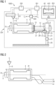
- FIG 1 shows a design of the digital twin system 1000.
- the figure shows a virtual part 203 and a physical part 204.
- a detection element 200 e.g. an ultrasound probe, is also shown.
- a movement of the detection element 200 is represented by C1 and C2.
- the figure shows a data transmission element 201 for data transmission between the physical part 204 and the virtual part 203.
- the virtual part 203 has a digital image 4D of the body 4.
- the winding 41 also has a digital image 41D in the figure.
- the detection element 200 is designed to detect data of the impregnating material 6 within the body 4 and/or on the body, in particular a course and/or a fill level of the impregnating material.
- the data can be transmitted to the virtual part 203 by the data transmission element 201, wherein the digital image of the body 4D can be changed depending on the data.
- the figure also shows a controller 202.
- the controller 202 can receive data from the data transmission element 201 and thus, for example, instruct the trickling unit 51 to dispense more impregnation material or to dispense impregnation material at another location.
- the figure also shows a software object 400.
- the software object 400 serves as a digital image 4D of the physical body to be impregnated.
- the figure shows an impregnation device 10.
- the impregnation device 10 for impregnating a body carrying at least one winding 41 has: a drive 11 with a drive shaft 12, wherein the drive 11 is designed to move the body 4 about the rotation axis A.
- the drive shaft 12 has at least one fastening element 13 for detachably connecting the body 4 to the drive shaft 12.
- the impregnation device 10 shown in the figure also has the dripping unit 51, wherein the dripping unit 51 is designed to drip the body 4 with the impregnation material 6.
- the trickling unit 51 has the dosing nozzle 5 and a reservoir 7 in which the impregnating material 6 is kept. It can also be mixed and/or preheated there.
- the trickling unit 51 can, for example, be moved along an axis B.
- the impregnation device 10 shown has a connection unit 24, wherein the connection unit 24 is designed to connect the winding 41 to an electrical power supply.
- the power supply unit 25 is shown in the figure.
- the winding 41 is connected to the power supply unit by means of the stranded conductors LU, LV, LW. In the figure, this is achieved by means of a terminal plate 23.
- the stranded conductors are advantageously flexible.
- the stranded conductors are advantageously long enough that they connect the winding 41 to the energy supply unit 25 and do not break off or become detached even when the body makes three complete revolutions, for example. They can wrap around the drive shaft 12 and rest against it when rotating.
- the stranded conductors are long enough to allow between one and ten full turns.
- the stranded conductors LU, LV, LW wound on the drive shaft 12 are unwound again.
- the figure also shows a dealer 8.
- the figure shows an arm 20 and an arm 21 which are connected by means of a joint 22.
- This is an exemplary embodiment which enables the drive 11 or the body 4 to be tilted vertically in relation to the horizontal.
- Other shapes are also possible.
- stator 2 or rotor 3 (see FIG 4 ) is clamped onto the drive shaft 12 shown and secured by means of the fastening element 13.
- Other mounting devices are also possible.
- a mounting device which is designed to rotate the body 4 about its longitudinal axis is advantageous.
- the impregnation material 6 is preferably liquid.
- the impregnation material 6 is, for example, dripped onto the winding heads and can be distributed in the winding head without dripping and homogeneously due to the rotary movement.
- the impregnation material can be advantageously drawn into existing grooves due to the capillary forces that occur.
- the stator 2 Since the stator 2 is heated by the current supply, the flowability of the impregnating material 6, preferably the resin, is improved. In addition, gelling and hardening of the impregnating material 6 is brought about particularly well.
- the movement pattern and/or the current supply can be regulated by the controller 202.
- Artificial intelligence can also be used to specify in advance how the impregnation should take place. During the impregnation process, improvements can also be made.
- the feed lines or electrical supply lines in the figure as stranded conductors LU, LV and LW, are advantageously arranged axially.
- a supply of impregnating material, in particular resin or a material containing resin, can be achieved through the nozzle 5.
- the resin can also be supplied via an axially arranged supply line, which, for example, supplies a premixed 2-component resin to at least one winding head.
- the viscosity can be reduced by the temperature of the winding system generated and controlled thereby. of the impregnation material can be influenced and changed.
- the impregnation can be intervened in and improved.
- a different movement pattern and/or temperature control via current flow in winding 41 can be carried out.
- the controller 202 can advantageously control both the drive 11 and the trickling unit 51.
- movement patterns and/or temperature settings of the winding specified by artificial intelligence can be optimized via adjustable current strength and the impregnation process can be improved in terms of resources, in particular with regard to optimized resin quantity for the respective axle height, length of the stator, winding system, number and volume of the slots, copper fill factor.
- Optimizing the timing and avoiding unnecessary rework such as free turning of the stator bore and cooling is also an advantage.
- FIG 2 shows a body 4 carrying a winding 41.
- Body 4 for example, is the one in FIG 1 shown rotor 3 or the stator 2.
- other bodies carrying a winding 41 can also be impregnated by means of the method.
- the body 4 is impregnated in the figure by dripping impregnating material 6, in particular resin or a resin-containing mixture, onto it by means of a dosing nozzle 5.
- the body 4 is moved about a rotation axis A before and/or during and/or after the sprinkling.
- the reference symbol R1 shows that the body 4 is rotated by a first angle in a first direction of rotation, preferably in a positive direction of rotation.
- the reference symbol R2 shows that the body is rotated by the negative first angle. This is shown in FIG 6 clarified.
- the body is rotated by a second angle in a second direction of rotation, preferably in a negative direction of rotation. This is FIG 7 clarified.
- FIG 3 shows the body 4, tilted vertically in relation to the horizontal.
- a tilt angle ⁇ that lies between 5° and 60° with respect to the horizontal is advantageous.
- a tilt angle ⁇ of between 10° and 35° with respect to the horizontal is particularly good.
- a stator When filled from one side from a resin reservoir, a stator, for example, can be easily filled.
- the impregnation material 6, in particular Resin then flows, due to the inclination and a suitable rotational movement along the slots, essentially axially through the stator, for example via capillaries of the winding in the slots, until it reaches and fills the winding head on the other side of the stator.
- the impregnating material flows preferentially in the winding until it reaches a certain saturation point.
- the invention makes it easy to precisely dose the correct amount of impregnating material for the stator 2.
- FIG 4 shows a dynamoelectric rotary machine 1 with a stator 2, a rotor 3 and a shaft 31.
- the rotor and/or stator were impregnated using the described procedure.
- FIG 5 shows the procedure
- a process step S1 the body 4 (see FIG 1 ) through which current flows. This heats up the body 4.
- step S3 the body 4 is rotated in the first direction of rotation R1 and in the second direction of rotation R2.
- a pendulum rotation advantageously takes place.
- the detection element 200 detects data of the impregnation material 6 within the body and/or on the body, in particular a course and/or a fill level of the impregnation material.
- step S5 data is transmitted through the data transmission element 201 to the virtual part 203.
- the data preferably includes information on the fill level and flow of the impregnation material. Other information may also be included.
- a process step S6 the digital image of the body is changed depending on the data.
- the dosing nozzle 5 can be moved circumferentially and/or axially while it is discharging impregnating material. However, the discharge of the impregnating material can also be stopped if the dosing nozzle is to be moved.
- a homogeneous distribution of the impregnation material, for example in the winding head, or e.g. in slots of the rotor or stator, can thus be easily achieved.
- the reversal speed, the position of the dosing nozzles, the temporary reduction of the dosing quantity before and during the reversal and the temporal variance of successive reversal processes can be varied, for example depending on the type and size of the body.
- the dosing amount can be maximized during a full rotation and then minimized during the reversal process to prevent dripping.
- the reversal process can be carried out, for example, after every 360° (or whole multiples thereof) or after variable angles of rotation (e.g. 1. 360°, 2. -365°, 3. +370°, ...) to ensure the most homogeneous distribution possible.
- the connecting lines or feed lines can also be designed to be so flexible and long that only a few or no reversals are necessary during the actual dosing process.
- the length and type of the connecting lines should be selected so that the Joule losses in the connecting lines are as low as possible.
- FIG 8 shows possible movement patterns of the body over time t.
- the body can rotate uniformly, see course V of the solid line for a rotation of 360°. However, the body can also rotate during a rotation as shown by the dashed line.
- FIG 9 shows a possible temperature profile of the winding. Heating is achieved advantageously by supplying current to the winding.
- FIG 10 shows details of stator 2.
- the stator has winding heads 41B.
- a bearing plate 9 is also shown.
- a nozzle 5B can also be moved inside the stator 2 and impregnate inside the stator bore or the recess inside the stator.
- a detection element 200B can also be positioned there, a possible direction of movement is shown with C1B and C2B.
- a 2D digital image of the stator is shown in the virtual part 203.
- the virtual part 203 can be present on a computing unit at the location of the impregnation device.
- the virtual part 203 can also be located in a cloud or at another location.
Landscapes
- Engineering & Computer Science (AREA)
- Manufacturing & Machinery (AREA)
- Power Engineering (AREA)
- Manufacture Of Motors, Generators (AREA)
Priority Applications (4)
| Application Number | Priority Date | Filing Date | Title |
|---|---|---|---|
| EP23169844.0A EP4456384A1 (fr) | 2023-04-25 | 2023-04-25 | Système double numérique |
| CN202480042714.0A CN121399830A (zh) | 2023-04-25 | 2024-02-15 | 数字孪生系统 |
| PCT/EP2024/053857 WO2024223094A1 (fr) | 2023-04-25 | 2024-02-15 | Système de jumeau numérique |
| EP24707700.1A EP4702648A1 (fr) | 2023-04-25 | 2024-02-15 | Système de jumeau numérique |
Applications Claiming Priority (1)
| Application Number | Priority Date | Filing Date | Title |
|---|---|---|---|
| EP23169844.0A EP4456384A1 (fr) | 2023-04-25 | 2023-04-25 | Système double numérique |
Publications (1)
| Publication Number | Publication Date |
|---|---|
| EP4456384A1 true EP4456384A1 (fr) | 2024-10-30 |
Family
ID=86227017
Family Applications (2)
| Application Number | Title | Priority Date | Filing Date |
|---|---|---|---|
| EP23169844.0A Withdrawn EP4456384A1 (fr) | 2023-04-25 | 2023-04-25 | Système double numérique |
| EP24707700.1A Pending EP4702648A1 (fr) | 2023-04-25 | 2024-02-15 | Système de jumeau numérique |
Family Applications After (1)
| Application Number | Title | Priority Date | Filing Date |
|---|---|---|---|
| EP24707700.1A Pending EP4702648A1 (fr) | 2023-04-25 | 2024-02-15 | Système de jumeau numérique |
Country Status (3)
| Country | Link |
|---|---|
| EP (2) | EP4456384A1 (fr) |
| CN (1) | CN121399830A (fr) |
| WO (1) | WO2024223094A1 (fr) |
Citations (5)
| Publication number | Priority date | Publication date | Assignee | Title |
|---|---|---|---|---|
| CH499224A (de) * | 1969-04-18 | 1970-11-15 | Veser F | Träufelimprägniereinrichtung für die Wicklung einer elektrischen Maschine und Verfahren zum Betrieb derselben |
| GB1241416A (en) * | 1967-08-02 | 1971-08-04 | Newage Lyon Ltd | Improvements relating to the manufacture of wound electrical rotors |
| DE3916619A1 (de) * | 1989-05-22 | 1990-11-29 | Gottlob Thumm Gmbh | Verfahren und anlage zum unterdruck-impraegnieren |
| DE4334959A1 (de) * | 1992-10-13 | 1994-04-14 | Reliance Electric Ind Co | Vorrichtung und Verfahren zum Beschichten einer elektromagnetischen Spule |
| EP1610445A1 (fr) * | 2003-09-10 | 2005-12-28 | Aisin Aw Co., Ltd. | Dispositif et procede de fabrication d'une machine electrique rotative |
-
2023
- 2023-04-25 EP EP23169844.0A patent/EP4456384A1/fr not_active Withdrawn
-
2024
- 2024-02-15 EP EP24707700.1A patent/EP4702648A1/fr active Pending
- 2024-02-15 CN CN202480042714.0A patent/CN121399830A/zh active Pending
- 2024-02-15 WO PCT/EP2024/053857 patent/WO2024223094A1/fr not_active Ceased
Patent Citations (5)
| Publication number | Priority date | Publication date | Assignee | Title |
|---|---|---|---|---|
| GB1241416A (en) * | 1967-08-02 | 1971-08-04 | Newage Lyon Ltd | Improvements relating to the manufacture of wound electrical rotors |
| CH499224A (de) * | 1969-04-18 | 1970-11-15 | Veser F | Träufelimprägniereinrichtung für die Wicklung einer elektrischen Maschine und Verfahren zum Betrieb derselben |
| DE3916619A1 (de) * | 1989-05-22 | 1990-11-29 | Gottlob Thumm Gmbh | Verfahren und anlage zum unterdruck-impraegnieren |
| DE4334959A1 (de) * | 1992-10-13 | 1994-04-14 | Reliance Electric Ind Co | Vorrichtung und Verfahren zum Beschichten einer elektromagnetischen Spule |
| EP1610445A1 (fr) * | 2003-09-10 | 2005-12-28 | Aisin Aw Co., Ltd. | Dispositif et procede de fabrication d'une machine electrique rotative |
Non-Patent Citations (2)
| Title |
|---|
| GANGREKAR YAKUB ET AL: "Automated Assembly Line Sorting Using LabVIEW as SCADA", 2019 GLOBAL CONFERENCE FOR ADVANCEMENT IN TECHNOLOGY (GCAT), IEEE, 18 October 2019 (2019-10-18), pages 1 - 5, XP033702456, DOI: 10.1109/GCAT47503.2019.8978382 * |
| HALENAR IGOR ET AL: "Virtualization of Production Using Digital Twin Technology", 2019 20TH INTERNATIONAL CARPATHIAN CONTROL CONFERENCE (ICCC), IEEE, 26 May 2019 (2019-05-26), pages 1 - 5, XP033577532, DOI: 10.1109/CARPATHIANCC.2019.8765940 * |
Also Published As
| Publication number | Publication date |
|---|---|
| WO2024223094A1 (fr) | 2024-10-31 |
| EP4702648A1 (fr) | 2026-03-04 |
| CN121399830A (zh) | 2026-01-23 |
Similar Documents
| Publication | Publication Date | Title |
|---|---|---|
| DE69731754T2 (de) | Verfahren und vorrichtung zum wickeln und formen von wicklungen elektrischer maschinen | |
| DE102011008662A1 (de) | Nadelwickelsystem für zu bewickelnde Wicklungsträger, Verfahren zum Bewickeln von Wicklungsträgern mit verteilter Wicklung, Innenläufer-Stator, Außenläufer-Rotor und Wicklungsträger für Elektromotorn mit verteilter Wicklung | |
| DE3686513T2 (de) | Anordnung bestehend aus einem durchlochten kern, einer harzhaltigen rohrplatte und einem selbstfixierenden spiralfoermig gewickelten hohlfaserbuendel. | |
| DE3631980C2 (fr) | ||
| DE1463870B2 (de) | Vorrichtung zur ausbildung einer isolierschicht in statornuten | |
| EP4456384A1 (fr) | Système double numérique | |
| DE102013017299A1 (de) | Verfahren und System zum Imprägnieren, Verfestigen oder Elektroisolieren eines ein-oder mehrlagige Wicklungen tragenden Körpers | |
| DE2728635A1 (de) | Verfahren zur herstellung der zylindrischen laeuferwicklung einer kernlosen elektrischen maschine | |
| DE1956936A1 (de) | Verfahren und Maschine zur halbkontinuierlichen Herstellung von Wendelhohlleitern grosser Laenge | |
| DE3540543C2 (fr) | ||
| DE3521152A1 (de) | Verfahren und vorrichtung zum vermeiden von bildwicklungen beim wickeln einer kreuzspule | |
| DE19701307C2 (de) | Verfahren und Vorrichtung zum Beschichten elektrischer Wickelkörper mittels schmelzfähigen Pulvers | |
| EP4456392A1 (fr) | Procédé d'imprégnation et dispositif d'imprégnation | |
| EP4068577A1 (fr) | Stator pour une machine tournante électrique | |
| EP4702660A1 (fr) | Procédé d'imprégnation et dispositif d'imprégnation | |
| EP4456393A1 (fr) | Procédé d'imprégnation et dispositif d'imprégnation | |
| EP4609493B1 (fr) | Procédé d'imprégnation d'au moins un enroulement de fil d'un composant | |
| DE10252435A1 (de) | Verfahren und Anordnung zur Aushärtung von Spulen | |
| DE69404340T2 (de) | Verfahren und Vorrichtung zum Herstellen von Schweissmuffen die mit einem elektrischen Heizdraht versehen sind | |
| DE1665295A1 (de) | Verfahren und Vorrichtung zum Herstellen von Litzenkabeln nach dem mit hoher Geschwindigkeit arbeitenden Zug-Spiralen-System | |
| EP4622077A1 (fr) | Procédé de fabrication d'un composant pour une machine électrique et dispositif correspondant de fabrication du composant | |
| DE3116748C2 (fr) | ||
| DE2920749C2 (fr) | ||
| DE102022133665A1 (de) | Fertigungsverfahren und Vorrichtung zum Erstellen einer Isolierung an einem Wicklungsbauteil | |
| CH456754A (de) | Wickelmaschine für Statorspulen elektrischer Maschinen |
Legal Events
| Date | Code | Title | Description |
|---|---|---|---|
| PUAI | Public reference made under article 153(3) epc to a published international application that has entered the european phase |
Free format text: ORIGINAL CODE: 0009012 |
|
| STAA | Information on the status of an ep patent application or granted ep patent |
Free format text: STATUS: THE APPLICATION HAS BEEN PUBLISHED |
|
| AK | Designated contracting states |
Kind code of ref document: A1 Designated state(s): AL AT BE BG CH CY CZ DE DK EE ES FI FR GB GR HR HU IE IS IT LI LT LU LV MC ME MK MT NL NO PL PT RO RS SE SI SK SM TR |
|
| STAA | Information on the status of an ep patent application or granted ep patent |
Free format text: STATUS: THE APPLICATION IS DEEMED TO BE WITHDRAWN |
|
| 18D | Application deemed to be withdrawn |
Effective date: 20250501 |