EP4456392A1 - Procédé d'imprégnation et dispositif d'imprégnation - Google Patents
Procédé d'imprégnation et dispositif d'imprégnation Download PDFInfo
- Publication number
- EP4456392A1 EP4456392A1 EP23169843.2A EP23169843A EP4456392A1 EP 4456392 A1 EP4456392 A1 EP 4456392A1 EP 23169843 A EP23169843 A EP 23169843A EP 4456392 A1 EP4456392 A1 EP 4456392A1
- Authority
- EP
- European Patent Office
- Prior art keywords
- winding
- rotation
- angle
- determined
- impregnating
- Prior art date
- Legal status (The legal status is an assumption and is not a legal conclusion. Google has not performed a legal analysis and makes no representation as to the accuracy of the status listed.)
- Withdrawn
Links
Images



Classifications
-
- H—ELECTRICITY
- H02—GENERATION; CONVERSION OR DISTRIBUTION OF ELECTRIC POWER
- H02K—DYNAMO-ELECTRIC MACHINES
- H02K15/00—Processes or apparatus specially adapted for manufacturing, assembling, maintaining or repairing of dynamo-electric machines
- H02K15/12—Impregnating, moulding insulation, heating or drying of windings, stators, rotors or machines
Definitions
- the invention relates to a method for impregnation and an impregnation device.
- the impregnation of electric motors i.e. in particular the immersion, sprinkling or coating of the rotors and/or stators with, preferably liquid, impregnating resin and the usually subsequent, in particular thermal, curing is a particularly energy-intensive step in the manufacturing process of the motor.
- the invention is based on the object of improving the impregnation of electric motors.
- the object is achieved by a method according to claim 1, ie a method for impregnating a body carrying at least one winding, in particular for an electrical machine, for example for a rotor or stator, wherein the body is sprinkled with an impregnating material, preferably containing resin, wherein a capacitance between two phases of the winding is determined.
- a capacitance between a phase of the winding and ground potential is determined, wherein an amount of impregnating material absorbed is determined by a change in the capacitance, wherein the body is moved about an axis of rotation before and/or during and/or after the sprinkling, wherein current flows through the winding before and/or during and/or after the sprinkling in order to heat the winding, wherein a dosing amount and/or a dosing location and/or a feed of energy into the winding is adapted to change a winding temperature, in particular of the individual phases, depending on the determined capacitance.
- a single object measurement during the impregnation process as well as during the curing process is particularly advantageous here, so that the ongoing process can be individually intervened in, e.g. by changing the temperature and dosage amount. This saves resources and enables high-quality impregnation.
- a dosing location is, for example, a winding head (inside and/or outside, groove exit, different phases).
- the process is particularly well suited for rotors and/or stators of dynamoelectric rotary machines. Furthermore, the process is also suitable for impregnating electrical machines in general, e.g. transformers.
- impregnation advantageously means impregnating, solidifying or electrically insulating.
- the impregnating material preferably contains resin.
- the resin is preferably such that it hardens when the temperature increases.
- the impregnating material can contain only resin.
- the impregnating material can also contain a resin-hardener mixture in particular in the form of a multi-component resin system comprising at least two components, wherein a first component is a resin, wherein a second component is a hardener.
- the resin is preferably an epoxy resin.
- the hardener is advantageously amine-based.
- the body is moved around a rotation axis before and/or during and/or after the sprinkling.
- the body does not perform a constant rotation, but rather oscillates between two positions.
- An advantageous design is one in which the capacity is determined cyclically.
- a cycle lasts at least two seconds and at most 20 seconds, preferably at least five and at most ten seconds.
- An embodiment is advantageous according to which the body is rotated by a first angle in a first direction of rotation, preferably in a positive direction of rotation, wherein the body is rotated by the negative first angle or a second angle in a second direction of rotation, preferably in a negative direction of rotation.
- the body advantageously rotates in a pendulum rotation.
- the body advantageously does not perform a continuous movement with a certain angular velocity.
- An embodiment is advantageous according to which the body is moved in the first direction of rotation at a first rotational speed, wherein the body is moved in the second direction of rotation at a second rotational speed, wherein the first rotational speed is greater than the second rotational speed.
- first rotation speed and the second rotation speed can also be the same.
- the rotation speed is preferably between 5 1/min and 40 1/min.
- An advantageous design is one in which the rotational speed is adjusted depending on the determined capacity.
- An advantageous embodiment is one in which the impregnating material is directed onto the body or in the direction of the body by means of a dosing nozzle.
- Two or more dosing nozzles can also be designed.
- An embodiment is advantageous according to which a dosage amount applied to the body when it is moved in the first direction of rotation is greater than a dosage amount applied to the body when it is moved in the second direction of rotation.
- the dosing quantity can, for example, reach a maximum during a full rotation of 360° in the forward direction and then reach a minimum in the reverse direction.
- a transition from maximum to minimum can be abrupt.
- a transition from maximum to minimum can also be smooth.
- An advantageous embodiment is one in which the impregnating material is directed to an axial end of the body.
- the impregnating material e.g. resin
- the impregnating material is advantageously applied to the axial end of the body which is higher in relation to the earth's surface than the other axial end.
- the impregnating material can advantageously flow through the inclined position towards the other axial end or towards a point at which the impregnation is to end.
- the body can be completely or partially impregnated.
- the body rotates when the impregnating material is applied. In this way, a particularly homogeneous distribution of the impregnating material can be achieved.
- the nozzle can be moved.
- An advantageous embodiment is one in which the dosing nozzle is moved, preferably parallel to the body.
- the nozzle can be moved while the body is rotated.
- the nozzle can also be moved before the body is rotated and/or after the body has been rotated.
- a design in which the body is tilted vertically in relation to the horizontal is advantageous.
- a tilt angle of between 5° and 60° in relation to the horizontal is advantageous.
- An advantageous embodiment is one in which the first angle is n ⁇ 360°, where n is a natural number.
- Natural numbers are 1, 2, 3, 4, 5, 6, 7, ....
- An embodiment is advantageous according to which the second angle lies between -(n ⁇ 360° + 1°) and -(n ⁇ 360° + 10°), preferably -(n ⁇ 360° + 5°), where n is a natural number.
- a particularly homogeneous distribution of the impregnation material can be achieved by an exemplary sequence of angles: 360°, -365°, +370°, ...
- the Joule heating of the coil has the advantage of warming the entire body. Heating using an oven is then no longer necessary, which saves time and money. Energy is also saved.
- the body can be warmed in this way before, during and after impregnation.
- An advantageous embodiment is one in which a three-phase winding is traversed by three-phase alternating current, while a single-phase winding is traversed by single-phase alternating current.
- the supply lines of the stator are connected to the connecting lines provided by an impregnation device. This can also be achieved using a clamping plate, for example.
- the cross-section of the stranded conductors is advantageously larger than the cross-section of the winding.
- the connecting cables are connected or connectable to a power supply unit, which preferably provides energy in the form of three-phase alternating current.
- the three phases of the stator are energized, which causes the windings to heat up.
- the windings are advantageously designed as copper windings.
- the windings can be energized continuously. However, breaks are also possible.
- a rotor or a transformer or another electrical machine can also be impregnated.
- connection unit can have a clamping plate to which the winding ends can be clamped.
- connection unit can also comprise individual conductors that can be connected to the winding ends.
- connection unit can also include sliding contacts.
- An advantageous design is one in which the drive is designed to be vertically tiltable in relation to the horizontal.
- An advantageous embodiment is one in which the trickling unit comprises a dosing nozzle for discharging the impregnating material.
- the problem can also be solved by a rotor and/or stator impregnated using such a process.
- the invention offers the advantage that impregnation can be carried out in a resource-efficient manner, since the amount of resin dripped onto the body can be dosed precisely and individually, for example in comparison to known dipping methods.
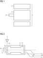
- FIG 1 shows a dynamoelectric rotary machine 1 with a stator 2, a rotor 3 and a shaft 31.
- the rotor and/or stator were impregnated using the described procedure.
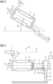
- FIG 2 shows a body 4 carrying a winding 41.
- Body 4 for example, is the one in FIG 1 shown rotor 3 or the stator 2.
- other bodies carrying a winding 41 can also be impregnated by means of the method.
- the body 4 is impregnated in the figure by dripping impregnating material 6, in particular resin or a resin-containing mixture, onto it by means of a dosing nozzle 5.
- the body 4 is moved about a rotation axis A before and/or during and/or after the sprinkling.
- the reference symbol R1 shows that the body 4 is rotated by a first angle in a first direction of rotation, preferably in a positive direction of rotation.
- the reference symbol R2 shows that the body is rotated by the negative first angle. This is shown in FIG 6 clarified.
- the body is rotated by a second angle in a second direction of rotation, preferably in a negative direction of rotation. This is FIG 7 clarified.
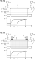
- FIG 3 shows the body 4, tilted vertically in relation to the horizontal.
- a tilt angle ⁇ that lies between 5° and 60° with respect to the horizontal is advantageous.
- a tilt angle ⁇ of between 10° and 35° with respect to the horizontal is particularly good.
- FIG 4 shows an impregnation device 10.
- the impregnation device 10 for impregnating a body carrying at least one winding, in particular for an electrical machine 1, in particular for carrying out the method according to one of the preceding claims, according to FIG 4 has: a drive 11 with a drive shaft 12, wherein the drive 11 is designed to move the body 4 about the rotation axis A.
- the drive shaft 12 has at least one fastening element 13 for releasably connecting the body 4 to the drive shaft 12.
- the impregnation device 10 shown in the figure also has a dripping unit 51, wherein the dripping unit 51 is designed to drip the body 4 with the impregnation material 6.
- the drip unit 51 has the dosing nozzle 5 and a reservoir 7 in which the impregnating material 6 is kept.
- the trickling unit 51 can, for example, be moved along an axis B.
- the impregnation device 10 shown has a connection unit 24, wherein the connection unit 24 is designed to connect the winding 41 to an electrical power supply.
- the power supply unit 25 is shown in the figure.
- the winding 41 is connected to the power supply unit by means of the stranded conductors LU, LV, LW. In the figure, this is achieved by means of a terminal plate 23.
- the stranded conductors are advantageously flexible.
- the stranded conductors are advantageously long enough that they connect the winding 41 to the energy supply unit 25 and do not break off or become detached even when the body makes three complete revolutions, for example. They can wrap around the drive shaft 12 and rest against it when rotating.
- the stranded conductors are long enough to allow between one and ten full turns.
- the stranded conductors LU, LV, LW wound on the drive shaft 12 are unwound again.
- the figure also shows a dealer 8.
- the figure shows an arm 20 and an arm 21 which are connected by means of a joint 22.
- This is an exemplary embodiment which enables the drive 11 or the body 4 to be tilted vertically in relation to the horizontal.
- Other shapes are also possible.
- stator 2 or rotor 3 (see FIG 1 ) is clamped onto the drive shaft 12 shown and secured by means of the fastening element 13.
- Other mounting devices are also possible.
- a mounting device which is designed to rotate the body 4 about its longitudinal axis is advantageous.
- the impregnation material 6 is preferably liquid.
- the impregnation material 6 is, for example, dripped onto the winding heads and can be distributed in the winding head without dripping and homogeneously due to the rotary movement.
- the impregnation material can be advantageously drawn into existing grooves due to the capillary forces that occur.
- the stator is heated by the current supply, the flowability of the impregnating material 6, preferably the resin, is improved. In addition, gelling and hardening of the impregnating material 6 is brought about particularly well.
- FIG 5 shows the procedure
- a process step S1 the body 4 (see FIG 4 ) through which current flows. The body 4 is thereby heated.
- the body 4 is rotated in a method step S3 in the first direction of rotation R1 and/or in the second direction of rotation R2. This can be repeated.
- a capacitance between two phases of the winding is determined.
- a capacitance between a phase of the winding and ground potential is determined, wherein an amount of impregnating material absorbed is determined by a change in the capacitance.
- a dosing quantity and/or a dosing location and/or a feed of energy into the Winding is adjusted to change a winding temperature, in particular of the individual phases, depending on the determined capacity.
- the dripping is completed in a process step S6.
- the discharge of the impregnating material is stopped and curing can take place.
- the dosing nozzle 5 can also be moved while it is discharging impregnating material.
- the discharge of the impregnating material can also be stopped if the dosing nozzle is to be moved.
- a homogeneous distribution of the impregnation material, for example in the winding head, or e.g. in slots of the rotor or stator, can thus be easily achieved.
- a reversal speed, a position of the dosing nozzles, a temporary reduction of the dosing quantity before and during the reversal as well as a temporal variance of successive reversal processes can be varied - e.g. depending on the type and size of the body.
- the dosing amount can be maximized during a full rotation and then minimized during the reversal process to prevent dripping.
- the reversal process can take place, for example, every 360° (or whole multiples thereof) or after variable angles of rotation (e.g. 1. 360°, 2. -365°, 3. +370°, ...) in order to ensure the most homogeneous distribution possible.
- the connecting lines can also be designed to be so flexible and long that only a few or no reversals are necessary during the actual dosing process.
- the length and type of the connecting lines should be selected so that the Joule losses in the connecting lines are as low as possible.
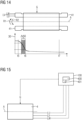
- FIG 8 - FIG 11 show the process of absorption of the impregnation material, especially resin absorption.
- the abscissa indicates a time course t, which shows the absorption of the impregnation material, see FIGS 8 to 11 , and networking, see FIGS 12 to 14
- the ordinate indicates a capacity 30, in particular a capacity increase in the FIGS 8 to 11 and a reduction in capacity in the FIGS 12 to 14 .
- the absorption of the impregnation material 6 begins at t1 in FIG 1 in that the nozzle 5 applies the impregnating material 6, preferably drop by drop, to the winding 41 or sprinkles it onto the winding 41.
- the winding 41 is advantageously arranged at least partially in grooves of the body 4, in particular the laminated core. Winding heads are advantageously formed at an axial front end and at an axial rear end.
- another nozzle 5a can apply impregnating material 6a to another end of the winding 41.
- FIG 11 also shows that by contacting individual sheets 39 a better resolution is possible and thus a capacitance of U against earth, V against earth and W against earth can be better determined.
- the invention is advantageous because it enables measurement and processing of the electrical capacitances between individual phases U, V and W or the respective capacitances between the aforementioned phases and the iron sheet (earth). From the information obtained from this, advantageously in real time, parameters such as dosing quantity, dosing location (in particular winding head inside and/or outside, slot exit, various phases), winding temperature of the individual phases can be adjusted during the ongoing process.
- a particular advantage is that the trickle technology, in particular the possibility of adjusting the amount of resin to be introduced in a targeted manner in terms of time and location, as well as the possibility of being able to adjust the winding temperature directly and individually for each phase via the connected lines, in combination with the knowledge of the resin filling quantity, in particular within the winding heads and the individual grooves, allows a highly precise, component-specific process. Energy and resources can also be saved.
- the measurement of the capacities can be divided into two areas, a dosing area (see FIG 8 to FIG 11 ) and a gelling or hardening area ( FIG 12 to FIG 14 ) are divided into
- the air in the spaces between the winding, in particular in the spaces between the enameled wires is advantageously displaced by the preferably liquid impregnating material. This advantageously increases the measured capacitance successively due to its high dielectric number (>10).
- phase-phase capacitance advantageously indicates the filling of the impregnation material in the winding heads (broken down into the individual areas of the winding head).
- phase(s)-earth capacitance advantageously indicates the filling quantity in the individual slots.
- an optimal distribution of the impregnation material can be ensured in a targeted manner, in particular by synchronizing the rotation speed and thus the angular position of the critical areas with the dosage amount.
- a fill level distribution over time can be determined.
- the cross-linking advantageously leads to a reduction in the dielectric constant up to the final state of complete cross-linking, which, depending on the resin chemistry and the number and nature of polar groups, has a dielectric constant advantageous between 2 and 5.
- This process is advantageously reflected in the measurement of the capacities, whereby a measurement of the variable capacities can be used to make a statement about the degree of cross-linking and thus about the remaining viscosity, which determines the cycle time in a trickle system.
- thermokinetic simulations which are part of the European patent application with the application number 22183330.4 are, a process-related advantage can be generated here, for example by determining the necessary degree of gelation for each component individually, which can vary depending on the component size and condition, during ongoing operation and thus initiating component removal or specifically catalyzing the curing reaction via single-phase current supply.
- FIG 12, 13 and 14 show a reduction in capacity 30.
- the reduction in capacity is essentially a consequence of gelation (cross-linking).
- t5 (see FIGS 12 and 13 ) is the beginning of cross-linking, in t6 a gelling point, in t7 complete cross-linking at room temperature occurs.
- a drip-free stator is advantageously present, whereby this is particularly dependent on cycle times and also variant.
- Capacity threshold values can indicate a degree of cross-linking and cycle times can thus be optimized in situ. This is particularly successful if a capacity curve over the cross-linking process is known in correlation with the viscosity.
- the impregnating material acts as a dielectric, preferably liquid, and gradually displaces air during the impregnation, the following applies: Capacity ⁇ ⁇ 0 ⁇ r geometry constant
- ⁇ r of air is 1, ⁇ r of liquid resin is advantageously between 10 and 15.
- trickling i.e. in particular the targeted dosing of a quantity of resin into specific areas of the stator, with the option of connecting a line (also known as reverse trickling), offers the possibility of carrying out various measurements on the stator or another body that has a winding during the ongoing process and of achieving targeted or partial heating of the winding. This means that for the first time, individual impregnation and hardening can be carried out in the so-called one-piece flow, regardless of variance. This offers the possibility of material and energy savings as well as cycle time optimization and thus productivity in production.
- FIG 15 shows a software object 400 acting as a digital twin of a body 4 carrying at least one winding 41.
- the body 4 is impregnated by means of the described method.
- a digital twin is advantageously a digital image or a data equivalent of the body 4, for example the rotor and/or the stator.
- the digital twin is therefore advantageously a data set which directly or indirectly includes all the data 401 which are necessary to describe the relevant properties of the body 4.
- the properties are, for example, dimensions of the body.
- the digital twin is particularly advantageous for the impregnation process. If the body 4 is sprinkled with an impregnating material 6, preferably containing resin, and a capacitance 30 between two phases of the winding is determined and/or a capacitance 30 between a phase the winding 41 against ground potential G is determined and a quantity of absorbed impregnating material is determined by a change in the capacitance 30, the body 4 can be moved about a rotation axis A before and/or during and/or after the dripping, in particular in order to distribute the impregnating material well. The impregnating material can thus be easily drawn into grooves, for example.
- the digital twin makes it possible to find out how long dripping should continue or whether a rotational movement is necessary to achieve good results.
- the digital twin can also provide information about which dosing quantity and/or dosing location and which energy input into the winding is necessary to change the winding temperature. For example, a control can be instructed to improve impregnation.
Landscapes
- Engineering & Computer Science (AREA)
- Manufacturing & Machinery (AREA)
- Power Engineering (AREA)
- Manufacture Of Motors, Generators (AREA)
Priority Applications (4)
| Application Number | Priority Date | Filing Date | Title |
|---|---|---|---|
| EP23169843.2A EP4456392A1 (fr) | 2023-04-25 | 2023-04-25 | Procédé d'imprégnation et dispositif d'imprégnation |
| CN202480042725.9A CN121420457A (zh) | 2023-04-25 | 2024-03-11 | 浸渍方法和浸渍设备 |
| EP24714796.0A EP4702659A1 (fr) | 2023-04-25 | 2024-03-11 | Procédé d'imprégnation et dispositif d'imprégnation |
| PCT/EP2024/056336 WO2024223131A1 (fr) | 2023-04-25 | 2024-03-11 | Procédé d'imprégnation et dispositif d'imprégnation |
Applications Claiming Priority (1)
| Application Number | Priority Date | Filing Date | Title |
|---|---|---|---|
| EP23169843.2A EP4456392A1 (fr) | 2023-04-25 | 2023-04-25 | Procédé d'imprégnation et dispositif d'imprégnation |
Publications (1)
| Publication Number | Publication Date |
|---|---|
| EP4456392A1 true EP4456392A1 (fr) | 2024-10-30 |
Family
ID=86226529
Family Applications (2)
| Application Number | Title | Priority Date | Filing Date |
|---|---|---|---|
| EP23169843.2A Withdrawn EP4456392A1 (fr) | 2023-04-25 | 2023-04-25 | Procédé d'imprégnation et dispositif d'imprégnation |
| EP24714796.0A Pending EP4702659A1 (fr) | 2023-04-25 | 2024-03-11 | Procédé d'imprégnation et dispositif d'imprégnation |
Family Applications After (1)
| Application Number | Title | Priority Date | Filing Date |
|---|---|---|---|
| EP24714796.0A Pending EP4702659A1 (fr) | 2023-04-25 | 2024-03-11 | Procédé d'imprégnation et dispositif d'imprégnation |
Country Status (3)
| Country | Link |
|---|---|
| EP (2) | EP4456392A1 (fr) |
| CN (1) | CN121420457A (fr) |
| WO (1) | WO2024223131A1 (fr) |
Citations (7)
| Publication number | Priority date | Publication date | Assignee | Title |
|---|---|---|---|---|
| CH499224A (de) * | 1969-04-18 | 1970-11-15 | Veser F | Träufelimprägniereinrichtung für die Wicklung einer elektrischen Maschine und Verfahren zum Betrieb derselben |
| GB1241416A (en) * | 1967-08-02 | 1971-08-04 | Newage Lyon Ltd | Improvements relating to the manufacture of wound electrical rotors |
| DE3916619A1 (de) * | 1989-05-22 | 1990-11-29 | Gottlob Thumm Gmbh | Verfahren und anlage zum unterdruck-impraegnieren |
| DE4334959A1 (de) * | 1992-10-13 | 1994-04-14 | Reliance Electric Ind Co | Vorrichtung und Verfahren zum Beschichten einer elektromagnetischen Spule |
| EP1610445A1 (fr) * | 2003-09-10 | 2005-12-28 | Aisin Aw Co., Ltd. | Dispositif et procede de fabrication d'une machine electrique rotative |
| JP2009201273A (ja) * | 2008-02-22 | 2009-09-03 | Toyota Motor Corp | ワニス処理方法、及びワニス処理装置 |
| EP3872962A1 (fr) | 2020-02-25 | 2021-09-01 | Siemens Aktiengesellschaft | Procédé d'imprégnation, de renforcement ou d'électroisolation d'un corps portant des enroulements mono- ou multicouche |
-
2023
- 2023-04-25 EP EP23169843.2A patent/EP4456392A1/fr not_active Withdrawn
-
2024
- 2024-03-11 EP EP24714796.0A patent/EP4702659A1/fr active Pending
- 2024-03-11 WO PCT/EP2024/056336 patent/WO2024223131A1/fr not_active Ceased
- 2024-03-11 CN CN202480042725.9A patent/CN121420457A/zh active Pending
Patent Citations (7)
| Publication number | Priority date | Publication date | Assignee | Title |
|---|---|---|---|---|
| GB1241416A (en) * | 1967-08-02 | 1971-08-04 | Newage Lyon Ltd | Improvements relating to the manufacture of wound electrical rotors |
| CH499224A (de) * | 1969-04-18 | 1970-11-15 | Veser F | Träufelimprägniereinrichtung für die Wicklung einer elektrischen Maschine und Verfahren zum Betrieb derselben |
| DE3916619A1 (de) * | 1989-05-22 | 1990-11-29 | Gottlob Thumm Gmbh | Verfahren und anlage zum unterdruck-impraegnieren |
| DE4334959A1 (de) * | 1992-10-13 | 1994-04-14 | Reliance Electric Ind Co | Vorrichtung und Verfahren zum Beschichten einer elektromagnetischen Spule |
| EP1610445A1 (fr) * | 2003-09-10 | 2005-12-28 | Aisin Aw Co., Ltd. | Dispositif et procede de fabrication d'une machine electrique rotative |
| JP2009201273A (ja) * | 2008-02-22 | 2009-09-03 | Toyota Motor Corp | ワニス処理方法、及びワニス処理装置 |
| EP3872962A1 (fr) | 2020-02-25 | 2021-09-01 | Siemens Aktiengesellschaft | Procédé d'imprégnation, de renforcement ou d'électroisolation d'un corps portant des enroulements mono- ou multicouche |
Non-Patent Citations (1)
| Title |
|---|
| ZIRNHELD J ET AL: "INSIGHTS INTO COIL PROCESSING", PROCEEDINGS OF THE ELECTRICAL INSULATION CONFERENCE AND ELECTRICAL MANUFACTURING AND COIL WINDING CONFERENCE. (COMBINED CONFERENCE). CINCINNATI, OH, OCT. 16 - 18, 2001; [PROCEEDINGS OF THE ELECTRICAL ELECTRONICS INSULATION CONFERENCE AND ELECTRICAL M, 16 October 2001 (2001-10-16), pages 467 - 472, XP001113694, ISBN: 978-0-7803-7180-4 * |
Also Published As
| Publication number | Publication date |
|---|---|
| CN121420457A (zh) | 2026-01-27 |
| WO2024223131A1 (fr) | 2024-10-31 |
| EP4702659A1 (fr) | 2026-03-04 |
Similar Documents
| Publication | Publication Date | Title |
|---|---|---|
| DE102011008662A1 (de) | Nadelwickelsystem für zu bewickelnde Wicklungsträger, Verfahren zum Bewickeln von Wicklungsträgern mit verteilter Wicklung, Innenläufer-Stator, Außenläufer-Rotor und Wicklungsträger für Elektromotorn mit verteilter Wicklung | |
| WO2001048895A1 (fr) | Procede de fabrication d'une isolation de qualite de conducteurs electriques ou de faisceaux de conducteurs de machines electriques rotatives par frittage par pulverisation | |
| EP4066353B1 (fr) | Procédé d'imprégnation, de renforcement ou d'électroisolation d'un corps portant des enroulements mono- ou multicouche | |
| DE3631980A1 (de) | Verfahren und impraegniermaschine zum impraegnieren von elektrischen maschinenteilen | |
| DE1463870B2 (de) | Vorrichtung zur ausbildung einer isolierschicht in statornuten | |
| EP4456392A1 (fr) | Procédé d'imprégnation et dispositif d'imprégnation | |
| DE102021201666A1 (de) | Nutisolationssystem für eine elektrische rotierende Maschine, Verfahren zur Herstellung eines Nutisolationssystems | |
| DE1956936A1 (de) | Verfahren und Maschine zur halbkontinuierlichen Herstellung von Wendelhohlleitern grosser Laenge | |
| DE3540543C2 (fr) | ||
| EP4456393A1 (fr) | Procédé d'imprégnation et dispositif d'imprégnation | |
| EP4456391A1 (fr) | Procédé d'imprégnation et dispositif d'imprégnation | |
| EP4068577A1 (fr) | Stator pour une machine tournante électrique | |
| EP4456384A1 (fr) | Système double numérique | |
| EP1742335B1 (fr) | Stator et procédé de fabrication d'un stator d'un moteur électrique | |
| EP2269285B1 (fr) | Procede et dispositif de fabrication d'un bobinage electrique | |
| EP4239869A1 (fr) | Procédé d'imprégnation d'un stator d'une machine dynamoélectrique | |
| DE2345043A1 (de) | Verfahren zum isolieren und verschliessen von spulen elektrischer geraete | |
| EP3945664B1 (fr) | Imprégnation d'une partie active d'une machine électrique en fonction de la longueur de la rainure et/ou du degré de remplissage | |
| EP0795225B2 (fr) | Procede de production d'une barre pour enroulements haute tension pour moteur electrique rotatif, munie de dispositifs anti-effluves | |
| DE102022133665A1 (de) | Fertigungsverfahren und Vorrichtung zum Erstellen einer Isolierung an einem Wicklungsbauteil | |
| DE202017007001U1 (de) | Temperierschlange | |
| DE2920749C2 (fr) | ||
| DE102017200606A1 (de) | Verfahren zum Aufbau einer Spule | |
| DE8712149U1 (de) | Imprägniermaschine zum Imprägnieren von elektrischen Maschinenteilen | |
| DE102023200958A1 (de) | Vorrichtung und Verfahren zur Herstellung eines Stators |
Legal Events
| Date | Code | Title | Description |
|---|---|---|---|
| PUAI | Public reference made under article 153(3) epc to a published international application that has entered the european phase |
Free format text: ORIGINAL CODE: 0009012 |
|
| STAA | Information on the status of an ep patent application or granted ep patent |
Free format text: STATUS: THE APPLICATION HAS BEEN PUBLISHED |
|
| AK | Designated contracting states |
Kind code of ref document: A1 Designated state(s): AL AT BE BG CH CY CZ DE DK EE ES FI FR GB GR HR HU IE IS IT LI LT LU LV MC ME MK MT NL NO PL PT RO RS SE SI SK SM TR |
|
| STAA | Information on the status of an ep patent application or granted ep patent |
Free format text: STATUS: THE APPLICATION IS DEEMED TO BE WITHDRAWN |
|
| 18D | Application deemed to be withdrawn |
Effective date: 20250501 |