EP4458697A1 - Procédé et machine pour envelopper des pailles - Google Patents
Procédé et machine pour envelopper des pailles Download PDFInfo
- Publication number
- EP4458697A1 EP4458697A1 EP24160221.8A EP24160221A EP4458697A1 EP 4458697 A1 EP4458697 A1 EP 4458697A1 EP 24160221 A EP24160221 A EP 24160221A EP 4458697 A1 EP4458697 A1 EP 4458697A1
- Authority
- EP
- European Patent Office
- Prior art keywords
- wrapping
- seat
- continuous
- continuous web
- straw
- Prior art date
- Legal status (The legal status is an assumption and is not a legal conclusion. Google has not performed a legal analysis and makes no representation as to the accuracy of the status listed.)
- Pending
Links
Images


Classifications
-
- B—PERFORMING OPERATIONS; TRANSPORTING
- B65—CONVEYING; PACKING; STORING; HANDLING THIN OR FILAMENTARY MATERIAL
- B65B—MACHINES, APPARATUS OR DEVICES FOR, OR METHODS OF, PACKAGING ARTICLES OR MATERIALS; UNPACKING
- B65B19/00—Packaging rod-shaped or tubular articles susceptible to damage by abrasion or pressure, e.g. cigarettes, cigars, macaroni, spaghetti, drinking straws or welding electrodes
- B65B19/34—Packaging other rod-shaped articles, e.g. sausages, macaroni, spaghetti, drinking straws, welding electrodes
-
- B—PERFORMING OPERATIONS; TRANSPORTING
- B31—MAKING ARTICLES OF PAPER, CARDBOARD OR MATERIAL WORKED IN A MANNER ANALOGOUS TO PAPER; WORKING PAPER, CARDBOARD OR MATERIAL WORKED IN A MANNER ANALOGOUS TO PAPER
- B31D—MAKING ARTICLES OF PAPER, CARDBOARD OR MATERIAL WORKED IN A MANNER ANALOGOUS TO PAPER, NOT PROVIDED FOR IN SUBCLASSES B31B OR B31C
- B31D5/00—Multiple-step processes for making three-dimensional [3D] articles
- B31D5/0095—Making drinking straws
-
- B—PERFORMING OPERATIONS; TRANSPORTING
- B65—CONVEYING; PACKING; STORING; HANDLING THIN OR FILAMENTARY MATERIAL
- B65B—MACHINES, APPARATUS OR DEVICES FOR, OR METHODS OF, PACKAGING ARTICLES OR MATERIALS; UNPACKING
- B65B9/00—Enclosing successive articles, or quantities of material, e.g. liquids or semiliquids, in flat, folded, or tubular webs of flexible sheet material; Subdividing filled flexible tubes to form packages
- B65B9/02—Enclosing successive articles, or quantities of material between opposed webs
- B65B9/04—Enclosing successive articles, or quantities of material between opposed webs one or both webs being formed with pockets for the reception of the articles, or of the quantities of material
- B65B9/045—Enclosing successive articles, or quantities of material between opposed webs one or both webs being formed with pockets for the reception of the articles, or of the quantities of material for single articles, e.g. tablets
-
- B—PERFORMING OPERATIONS; TRANSPORTING
- B65—CONVEYING; PACKING; STORING; HANDLING THIN OR FILAMENTARY MATERIAL
- B65B—MACHINES, APPARATUS OR DEVICES FOR, OR METHODS OF, PACKAGING ARTICLES OR MATERIALS; UNPACKING
- B65B9/00—Enclosing successive articles, or quantities of material, e.g. liquids or semiliquids, in flat, folded, or tubular webs of flexible sheet material; Subdividing filled flexible tubes to form packages
- B65B9/02—Enclosing successive articles, or quantities of material between opposed webs
- B65B9/04—Enclosing successive articles, or quantities of material between opposed webs one or both webs being formed with pockets for the reception of the articles, or of the quantities of material
- B65B2009/047—Rotary pocket formers
-
- B—PERFORMING OPERATIONS; TRANSPORTING
- B65—CONVEYING; PACKING; STORING; HANDLING THIN OR FILAMENTARY MATERIAL
- B65B—MACHINES, APPARATUS OR DEVICES FOR, OR METHODS OF, PACKAGING ARTICLES OR MATERIALS; UNPACKING
- B65B2220/00—Specific aspects of the packaging operation
- B65B2220/06—Cutting webs along their longitudinal direction
-
- B—PERFORMING OPERATIONS; TRANSPORTING
- B65—CONVEYING; PACKING; STORING; HANDLING THIN OR FILAMENTARY MATERIAL
- B65B—MACHINES, APPARATUS OR DEVICES FOR, OR METHODS OF, PACKAGING ARTICLES OR MATERIALS; UNPACKING
- B65B25/00—Packaging other articles presenting special problems
-
- B—PERFORMING OPERATIONS; TRANSPORTING
- B65—CONVEYING; PACKING; STORING; HANDLING THIN OR FILAMENTARY MATERIAL
- B65B—MACHINES, APPARATUS OR DEVICES FOR, OR METHODS OF, PACKAGING ARTICLES OR MATERIALS; UNPACKING
- B65B41/00—Supplying or feeding container-forming sheets or wrapping material
- B65B41/12—Feeding webs from rolls
-
- B—PERFORMING OPERATIONS; TRANSPORTING
- B65—CONVEYING; PACKING; STORING; HANDLING THIN OR FILAMENTARY MATERIAL
- B65B—MACHINES, APPARATUS OR DEVICES FOR, OR METHODS OF, PACKAGING ARTICLES OR MATERIALS; UNPACKING
- B65B61/00—Auxiliary devices, not otherwise provided for, for operating on sheets, blanks, webs, binding material, containers or packages
- B65B61/20—Auxiliary devices, not otherwise provided for, for operating on sheets, blanks, webs, binding material, containers or packages for adding cards, coupons or other inserts to package contents
- B65B61/205—Auxiliary devices, not otherwise provided for, for operating on sheets, blanks, webs, binding material, containers or packages for adding cards, coupons or other inserts to package contents for adding drinking straws to a container
Definitions
- the present invention relates to a method and to a machine for wrapping straws.
- Straws which have a corrugated intermediate portion aimed to allow the bending of the straw in order to assume, in use, a more suitable shape to satisfy the user.
- a straw is individually packaged (namely, it is inserted singularly in its own wrap) after being bent in a "U" shape (i.e., by 180°) in the area of the corrugated intermediate portion (the purpose of the "U” bending is to reduce the overall dimensions of the straw); typically, it is required to individually package the straws bent in a "U” shape when the straws must be fixed (glued) to the rear wall of a beverage container.
- a known wrapping machine for individually packaging straws comprises: a hopper containing a mass of straws, a pick-up drum that picks up the straws from the hopper, a bending drum that bends each straw, and a wrapping drum, which has a plurality of suitable sucking seats each designed to house a portion of a first continuous (i.e., seamless) web of wrapping material and a straw.
- Each sucking seat of the wrapping drum receives a portion of the first web of wrapping material that is arranged folded in a "U" shape inside the sucking seat to define a pocket and therefore receives subsequently and directly from the bending drum a straw (which is placed inside the pocket).
- An applicator drum is coupled to the wrapping drum, which applies (typically by heat sealing) to the first web of wrapping material a second web of wrapping material that closes the pockets containing the straws. Then, a continuous (i.e., seamless) succession of pockets each containing a straw is fed out of the wrapping drum; said continuous succession of pockets, each containing a straw, is referred to as a " cartridge belt " in jargon.
- Patent application WO2021250715A1 describes a machine for wrapping straws comprising a feeding unit configured to feed a plurality of paper straws towards different working units configured to automatically perform different processes on the straws, comprising a deformation in order to form a bellows, a cutting, following the deformation, to create a pointed end cut obliquely, a bend in the area of the bellows, and a packaging of each straw.
- the object of the present invention is to provide a method and a machine for wrapping straws which allow, by working on a double line, to maintain a high operating speed (measured as the number of wrapped straws in a unit of time) without interruptions (namely, without unexpected stops) and, at the same time, to reduce defective packaging to a minimum even when continuous webs of paper-based wrapping material are used.
- number 1 denotes as a whole a straw (made of paper or plastic) which is applied to the back of a beverage package.
- the straw 1 has a flat end 2 (which is held by the lips of the user) and a pointed end 3 (to more effectively break through the cap that seals a dispensing opening of the package).
- the straw 1 has a corrugated intermediate portion 4 in the area of which the straw 1 can be bent easily and without breaking (namely, in an elastic manner) so as to assume, in use, the most suitable shape in order to satisfy the user.
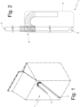
- the straw 1 is individually packaged (namely, it has been inserted singularly in its own wrap 5 not illustrated in Figure 1 and illustrated in Figure 2 ) after being bent in a "U" shape (i.e., by 180°) in the area of the corrugated intermediate portion 4 (the purpose of the "U" bending is to reduce the overall dimensions of the straw 1 so as to remain within the overall dimensions of the back wall of the package to which the straw 1 is applied).
- number 6 denotes as a whole a wrapping machine which receives the straight straws 1 from a processing machine (not illustrated), corrugates the straws 1, bends the straws 1 in a "U" shape, and inserts the straws 1 in corresponding wraps 5.
- the wrapping machine 6 comprises a hopper 7 which is designed to contain a mass of straight straws 1 coming from the wrapping machine and which move progressively downwards by gravity, namely, towards the bottom of the hopper 7.
- the wrapping machine 6 could provide any buffer or collector of a mass of straws.
- the wrapping machine 6 could receive the straws in an orderly manner (that is, not collected in a mass), for example directly from the processing machine.
- a pick-up conveyor 8 On the bottom of the hopper 7 a pick-up conveyor 8 is provided, which, in an input station S1 picks up a succession of straight straws 1, advancing the same transversally to (namely, perpendicularly to a longitudinal axis of the straws 1).
- the pick-up conveyor 8 is formed by a drum which is mounted so as to rotate around a rotation axis 9 (horizontal and perpendicular to the plane of Figure 3 ) and has a plurality of sucking seats each suitable for housing a corresponding straight straw 1.
- the pick-up conveyor 8 is a conveyor belt, namely, it comprises a flexible belt which is closed in a loop around two end pulleys and supports a plurality of sucking seats each suitable for housing a corresponding straight straw 1.
- the wrapping machine 6 comprises a corrugator drum 10 which is mounted so as to rotate around a rotation axis 11 (parallel to the rotation axis 9), has a plurality of seats each suitable for housing a corresponding straight straw 1, and receives the straight straws 1 directly from the pick-up conveyor 8 in a transfer station S2.
- a corrugator device 12 is arranged along the periphery of the corrugator drum 10, which corrugates the straight straws 1, namely, forms the corrugated intermediate portion 4 in each straight straw 1.
- the wrapping machine 6 could receive already corrugated straws 1; in this case, the wrapping machine 6 does not comprise the corrugator drum 10.
- the wrapping machine 6 comprises a bending drum 13 which is mounted so as to rotate around a rotation axis 14 (parallel to the rotation axis 11), has a plurality of seats each suitable for housing a corresponding initially straight straw 1, and receives the straight straws 1 directly from the corrugator drum 10 in a transfer station S3.
- Bending elements 15 are arranged around the rotation axis 14 in a fixed position (namely, integral with a frame of the wrapping machine 6 and therefore devoid of movement) which are coupled to the bending drum 13 and interact with the straws 1 carried by the seats so as to bend the straws 1 in a "U" shape.
- the wrapping machine 6 comprises a reject drum 16 which is mounted so as to rotate around a rotation axis 17 (parallel to the rotation axis 14), has a plurality of seats each suitable for housing a corresponding straw 1 bent in a "U" shape, receives the straws 1 directly from the bending drum 13 in a transfer station S4, and releases the bent straws 1 in a transfer station S5 arranged downstream of the transfer station S4 relative to the rotation direction of the reject drum 16.
- the wrapping machine 6 comprises a wrapping drum 18, which is mounted so as to rotate around a rotation axis 19 (parallel to the rotation axis 18), has a plurality of sucking seats 20 (illustrated in Figures 4 and 5 ) each suitable for housing a portion of a continuous (i.e., seamless) web 21 of wrapping material and a straw 1 bent in a "U" shape.
- the rotation of the wrapping drum 18 around the rotation axis 19 cyclically advances the sucking seats 20 along a circular wrapping path P.
- the wrapping drum 18 is replaced by a conveyor belt comprising a flexible belt which is closed in a loop around two end pulleys and supports a plurality of sucking seats 20 each suitable for housing a corresponding straw 1 bent in a "U" shape; in this embodiment, the wrapping path P is at least partially straight.
- Each sucking seat 20 of the wrapping drum 18 receives, in a feeding station S6, a portion of the continuous web 21 of wrapping material that is arranged folded in a "U" shape inside the sucking seat 20 to define a pocket (which will become a respective wrap 5) and then receives subsequently and directly from the reject drum 17 in the transfer station S5 a bent straw 1 (which is placed inside the pocket previously formed in the sucking seat 20).
- each wrap 5 is formed by the union of a portion of a continuous web 21 (having a cradle-like shape) with a portion of a continuous web 24 (having a flat shape to form the " lid " for the cradle).
- a continuous succession i.e., seamless
- wraps 5 each containing a bent straw 1
- said continuous succession of pockets each containing a bent straw 1 is referred to as a " cartridge belt " in jargon.
- the wrapping machine 6 comprises an output conveyor 25, which receives the " cartridge belt “ (namely, it receives a continuous web 5 of wrapping material containing respective bent straws 1) from the wrapping drum 18 and moves the " cartridge belt “ towards an output of the wrapping machine 6.
- the wrapping machine 6 operates on a double line, namely, it treats two straws 1 arranged side by side (that is, axially aligned with one another) at a time.
- the pick-up conveyor 8 has a series of pairs of sucking seats (axially aligned with one another) to pick up two straws 1 at a time from the output mouth of the hopper 7
- the corrugator drum 10 has a series of pairs of seats (axially aligned with one another), which simultaneously receive two straight straws 1 from the pick-up conveyor 8, simultaneously corrugate two straws 1 together with the corrugator device 12, and simultaneously release two straight straws 1 to the bending drum 13.
- the bending drum 13 has a series of pairs of seats (axially aligned with one another or arranged side by side and aligned along a direction perpendicular to an advancement direction of the bending drum 13) which simultaneously receive two straight straws 1 from the corrugator drum 10, simultaneously bend two straws 1, and simultaneously release two bent straws 1 to the reject drum 16.
- the reject drum 16 has a series of pairs of seats (axially aligned with one another) which simultaneously receive two bent straws 1 from the bending drum 13 and simultaneously release two bent straws 1 to the wrapping drum 18.
- the wrapping drum 18 has a series of pairs of sucking seats 20 (axially aligned with one another), which simultaneously receive two bent straws 1 from the reject drum 16, simultaneously form two wraps 5 (operating with respective continuous webs 21 and 24 of wrapping material), and simultaneously release two wraps 5 to the output conveyor 25.
- the output conveyor 25 has a series of pairs of sucking seats (axially aligned with one another) which simultaneously receive two wraps 5 (and therefore two " cartridge belts ”) from the wrapping drum 18.
- the wrapping drum 18 moves, along the circular wrapping path P, a series of pairs of sucking seats 20 which are arranged side by side and are each suitable to house a straw 1.
- the feeding station S6 arranged along the wrapping path P
- a portion of the continuous web 21 of wrapping material is fed, which is arranged bent in a "U" shape inside the sucking seat 20 so as to define a pocket.
- the transfer station S5 arranged downstream of the feeding station S6 along the wrapping path P
- a straw 1 bent in a "U” shape is transferred to each sucking seat 20 and placed inside a respective pocket.
- the continuous web 24 of wrapping material is fed over each sucking seat 20 which closes each pocket containing a respective straw 1 (thus completing the formation of the respective wrap 5).
- the hopper 7 contains straight straws 1 having a double length (namely, equal to double the length of a straw 1 coming out of the wrapping machine 6) which are cut in half by a cutting device 26 coupled to the pick-up conveyor 8.
- two continuous twin webs 21 are fed into the feeding station S6, which are separated from one another and arranged side by side so that a continuous web 21 is arranged at the sucking seats 20 located on the right and the other continuous web 21 is arranged at the sucking seats 20 located on the left. That is, considering a single pair of sucking seats 20 axially side by side, a continuous web 21 is arranged at a right sucking seat 20 and the other continuous web 21 is arranged at a left sucking seat 20.
- two continuous twin webs 24 are fed in the feeding station S7, which are separated from one another and arranged side by side so that a continuous web 24 is arranged at the sucking seats 20 located on the right and the other continuous web 24 is arranged at the sucking seats 20 located on the left. That is, considering a single pair of sucking seats 20 axially side by side, a continuous web 24 is arranged at a right sucking seat 20 and the other continuous web 24 is arranged at a left sucking seat 20.
- the two continuous webs 21 are unwound from two separate and independent reels 27 and similarly the two continuous webs 24 are unwound from two separate and independent reels 28.
- a single continuous web 21 having a double width is unwound from a single reel 27 and subsequently the single continuous web 21 having a double width is cut longitudinally to obtain the two continuous webs 21 from a cutting device 29; preferably, downstream of the cutting device 29 (namely, after the longitudinal cut) the two continuous webs 21 are spaced apart transversally by a spacer device 30.
- a single continuous web 24 having a double width is unwound from a single reel 28 and subsequently the single continuous web 24 having a double width is cut longitudinally to obtain the two continuous webs 24 by a cutting device 29; preferably, downstream of the cutting device 29 (namely, after the longitudinal cut) the two continuous webs 24 are spaced apart transversally by a spacer device 30.
- the wrapping machine 6 comprises a trimming device 31 (illustrated in Figure 3 ) which trims (cuts) each pocket (namely each " cartridge belt ”) longitudinally on both sides to eliminate the excess lateral portions of the continuous webs 21 and 24 (lateral portions which are in excess in the final wraps 5 but are necessary to achieve adequate mutual adhesion of the two continuous webs 21 and 24 at the moment of the formation of the wraps 5).
- a trimming device 31 illustrated in Figure 3
- the wrapping machine 6 comprises a trimming device 31 (illustrated in Figure 3 ) which trims (cuts) each pocket (namely each " cartridge belt ”) longitudinally on both sides to eliminate the excess lateral portions of the continuous webs 21 and 24 (lateral portions which are in excess in the final wraps 5 but are necessary to achieve adequate mutual adhesion of the two continuous webs 21 and 24 at the moment of the formation of the wraps 5).
- the continuous webs 21 and 24 are made of paper-based material (even if the wrapping machine 6 is perfectly capable of operating with continuous webs 21 and 24 made of plastic-based material).
- the wrapping machine 6 comprises a gluing device 32 (illustrated in Figure 3 ) which can be arranged (alternatively) at the continuous web 21 to apply glue on the continuous web 21 or can be arranged at the continuous web 24 to apply glue on the continuous web 24.
- Figure 3 illustrates two gluing devices 32 in two different positions, but it is clear that only one of the two gluing devices 32 is actually provided.
- the wrapping machine 6 described above has numerous advantages.
- the wrapping machine 6 described above by working on a double line, allows to maintain a high operating speed (measured as the number of straws 1 wrapped in a unit of time) without interruptions (namely, without unexpected stops) and, at the same time, to reduce defective wrap 5 to a minimum even when continuous webs 21 and 24 of paper-based wrapping material are used.
- This result is obtained due to the fact that by using two independent and side-by-side webs 21 and two independent and side-by-side webs 24 it is possible to reduce the mechanical stresses that occur in the webs 21 and 24 (particularly in the webs 21 when they have to deform to enter the sucking seats 20 of the wrapping drum 18) and therefore it is possible to substantially reduce (practically eliminate) the more or less partial tearing of a web 21 or 24.
- the continuous webs 21 and 24 of paper-based wrapping material are less flexible (namely, they are less able to absorb deformations without damage) compared to the similar continuous webs 21 and 24 made of plastic-based wrapping material and therefore, to avoid unwanted tears in the continuous webs 21 and 24 made of paper-based wrapping material, it is necessary to reduce the stresses (deformations) to which the continuous webs 21 and 24 made of paper-based wrapping material are subjected in use.
- the wrapping machine 6 described above requires minimal modifications compared to an existing wrapping machine and is therefore simple, inexpensive, and compact to manufacture.
Landscapes
- Engineering & Computer Science (AREA)
- Mechanical Engineering (AREA)
- Wrapping Of Specific Fragile Articles (AREA)
Applications Claiming Priority (1)
| Application Number | Priority Date | Filing Date | Title |
|---|---|---|---|
| IT202300003651 | 2023-03-01 |
Publications (1)
| Publication Number | Publication Date |
|---|---|
| EP4458697A1 true EP4458697A1 (fr) | 2024-11-06 |
Family
ID=86329248
Family Applications (1)
| Application Number | Title | Priority Date | Filing Date |
|---|---|---|---|
| EP24160221.8A Pending EP4458697A1 (fr) | 2023-03-01 | 2024-02-28 | Procédé et machine pour envelopper des pailles |
Country Status (1)
| Country | Link |
|---|---|
| EP (1) | EP4458697A1 (fr) |
Citations (2)
| Publication number | Priority date | Publication date | Assignee | Title |
|---|---|---|---|---|
| WO2021250715A1 (fr) | 2020-06-10 | 2021-12-16 | I.M.A. Industria Macchine Automatiche S.P.A. | Machine et procédé de production automatisée de pailles |
| CN115429086A (zh) * | 2022-08-18 | 2022-12-06 | 浙江金申机械制造有限公司 | 吸管的制造方法 |
-
2024
- 2024-02-28 EP EP24160221.8A patent/EP4458697A1/fr active Pending
Patent Citations (2)
| Publication number | Priority date | Publication date | Assignee | Title |
|---|---|---|---|---|
| WO2021250715A1 (fr) | 2020-06-10 | 2021-12-16 | I.M.A. Industria Macchine Automatiche S.P.A. | Machine et procédé de production automatisée de pailles |
| CN115429086A (zh) * | 2022-08-18 | 2022-12-06 | 浙江金申机械制造有限公司 | 吸管的制造方法 |
Similar Documents
| Publication | Publication Date | Title |
|---|---|---|
| US6021890A (en) | Bundle pack and process and apparatus for producing same | |
| EP0952085B1 (fr) | Procédé et dispositif pour former des paquets de cigarettes | |
| US20050138900A1 (en) | Sheet package producing system, sheet handling device, and fillet folding device | |
| US8307613B2 (en) | Equipment and method for packaging multiple packets of cigarettes | |
| JP5701912B2 (ja) | 梱包装置及び梱包方法 | |
| CN101070101A (zh) | 生产香烟盒的方法和包装机 | |
| CN100488851C (zh) | 带有撕开线的盒子以及生产此种盒子的方法和设备 | |
| EP4458697A1 (fr) | Procédé et machine pour envelopper des pailles | |
| US7216470B2 (en) | Sheet package producing system | |
| US20060042759A1 (en) | Device for processing flat objects, especially for packing printed products | |
| US5337536A (en) | Packaging apparatus | |
| CN101181938A (zh) | 片材供给装置及使用该装置的片材包装机 | |
| JP2763995B2 (ja) | 個別包装物の連続供給方法 | |
| EP4059849B1 (fr) | Procédé d'emballage et unité d'emballage pour articles, en particulier des pailles, avec rejet automatique d'articles défectueux | |
| EP4458698A1 (fr) | Procédé d'emballage et machine d'emballage pour pailles, avec orientation avant l'emballage | |
| ITBO980319A1 (it) | Metodo di incarto, particolarmente per prodotti alimentari quali ciocc olatini e simili, e confezione ottenuta. | |
| CN1678984B (zh) | 嵌入式插入物折叠器系统 | |
| ITBO20070028A1 (it) | Dispositivo per la predisposizione di una confezione di prodotto. | |
| KR100654332B1 (ko) | 샌드위치 포장대의 포장장치 | |
| CN219601723U (zh) | 一种全自动三维透明膜包装机 | |
| IT202300003660A1 (it) | Metodo e macchina di lavorazione di cannucce | |
| KR20200018561A (ko) | 면봉 포장시트 접합장치 | |
| EP3492397B1 (fr) | Machine d'emballage | |
| EP2407385B1 (fr) | Unité et procédé pour l'alimentation de feuilles de matériau pour emballer des paquets de cigarettes et machine pour emballer lesdits paquets | |
| GB2259072A (en) | Unit for packing packets of cigarettes in groups |
Legal Events
| Date | Code | Title | Description |
|---|---|---|---|
| PUAI | Public reference made under article 153(3) epc to a published international application that has entered the european phase |
Free format text: ORIGINAL CODE: 0009012 |
|
| STAA | Information on the status of an ep patent application or granted ep patent |
Free format text: STATUS: THE APPLICATION HAS BEEN PUBLISHED |
|
| AK | Designated contracting states |
Kind code of ref document: A1 Designated state(s): AL AT BE BG CH CY CZ DE DK EE ES FI FR GB GR HR HU IE IS IT LI LT LU LV MC ME MK MT NL NO PL PT RO RS SE SI SK SM TR |
|
| STAA | Information on the status of an ep patent application or granted ep patent |
Free format text: STATUS: REQUEST FOR EXAMINATION WAS MADE |
|
| 17P | Request for examination filed |
Effective date: 20250430 |