EP4459247A1 - Dispositif de transmission de courant pour un dispositif de mesure de force, en particulier un dispositif de pesée - Google Patents
Dispositif de transmission de courant pour un dispositif de mesure de force, en particulier un dispositif de pesée Download PDFInfo
- Publication number
- EP4459247A1 EP4459247A1 EP24166213.9A EP24166213A EP4459247A1 EP 4459247 A1 EP4459247 A1 EP 4459247A1 EP 24166213 A EP24166213 A EP 24166213A EP 4459247 A1 EP4459247 A1 EP 4459247A1
- Authority
- EP
- European Patent Office
- Prior art keywords
- housing
- connecting element
- power transmission
- transmission device
- designed
- Prior art date
- Legal status (The legal status is an assumption and is not a legal conclusion. Google has not performed a legal analysis and makes no representation as to the accuracy of the status listed.)
- Granted
Links
Images


Classifications
-
- H—ELECTRICITY
- H01—ELECTRIC ELEMENTS
- H01R—ELECTRICALLY-CONDUCTIVE CONNECTIONS; STRUCTURAL ASSOCIATIONS OF A PLURALITY OF MUTUALLY-INSULATED ELECTRICAL CONNECTING ELEMENTS; COUPLING DEVICES; CURRENT COLLECTORS
- H01R13/00—Details of coupling devices of the kinds covered by groups H01R12/70 or H01R24/00 - H01R33/00
- H01R13/62—Means for facilitating engagement or disengagement of coupling parts or for holding them in engagement
- H01R13/629—Additional means for facilitating engagement or disengagement of coupling parts, e.g. aligning or guiding means, levers, gas pressure electrical locking indicators, manufacturing tolerances
-
- G—PHYSICS
- G01—MEASURING; TESTING
- G01G—WEIGHING
- G01G21/00—Details of weighing apparatus
-
- G—PHYSICS
- G01—MEASURING; TESTING
- G01G—WEIGHING
- G01G21/00—Details of weighing apparatus
- G01G21/28—Frames, Housings
-
- G—PHYSICS
- G01—MEASURING; TESTING
- G01G—WEIGHING
- G01G21/00—Details of weighing apparatus
- G01G21/30—Means for preventing contamination by dust
-
- G—PHYSICS
- G01—MEASURING; TESTING
- G01L—MEASURING FORCE, STRESS, TORQUE, WORK, MECHANICAL POWER, MECHANICAL EFFICIENCY, OR FLUID PRESSURE
- G01L1/00—Measuring force or stress, in general
-
- H—ELECTRICITY
- H01—ELECTRIC ELEMENTS
- H01R—ELECTRICALLY-CONDUCTIVE CONNECTIONS; STRUCTURAL ASSOCIATIONS OF A PLURALITY OF MUTUALLY-INSULATED ELECTRICAL CONNECTING ELEMENTS; COUPLING DEVICES; CURRENT COLLECTORS
- H01R12/00—Structural associations of a plurality of mutually-insulated electrical connecting elements, specially adapted for printed circuits, e.g. printed circuit boards [PCB], flat or ribbon cables, or like generally planar structures, e.g. terminal strips, terminal blocks; Coupling devices specially adapted for printed circuits, flat or ribbon cables, or like generally planar structures; Terminals specially adapted for contact with, or insertion into, printed circuits, flat or ribbon cables, or like generally planar structures
- H01R12/70—Coupling devices
- H01R12/71—Coupling devices for rigid printing circuits or like structures
-
- H—ELECTRICITY
- H01—ELECTRIC ELEMENTS
- H01R—ELECTRICALLY-CONDUCTIVE CONNECTIONS; STRUCTURAL ASSOCIATIONS OF A PLURALITY OF MUTUALLY-INSULATED ELECTRICAL CONNECTING ELEMENTS; COUPLING DEVICES; CURRENT COLLECTORS
- H01R13/00—Details of coupling devices of the kinds covered by groups H01R12/70 or H01R24/00 - H01R33/00
- H01R13/73—Means for mounting coupling parts to apparatus or structures, e.g. to a wall
Definitions
- the invention relates to a current transmission device for a force measuring device, in particular a weighing device.
- Such a force measuring device can be, for example, a weighing device that has a conveyor belt with an electric drive that acts as a preload on a load cell arranged in a housing of the weighing device.
- both electrical supply lines are provided, which are led, for example, from a power supply unit provided in the housing of the weighing device or a power supply unit arranged on the housing of the weighing device in a separate housing to the electric drive of the conveyor belt, and communication lines that are led from a control unit provided in the housing of the weighing device to the electric drive of the conveyor belt.
- the entire housing can be filled with a protective gas atmosphere. Since a weighing device always requires a load receptor or an element coupled to it to be led out of the housing as contact-free as possible, i.e. with a low force shunt, it would be necessary to provide either a completely tight seal between the load receptor with the lowest possible force shunt, for example a bellows, or to provide a sufficiently small gap between the load receptor and the feedthrough opening, which can also be sealed using a labyrinth seal. With a completely tight seal, the housing can be filled (statically) with a protective gas atmosphere.
- protective gas must be continuously (dynamic protective gas atmosphere) to prevent the protective gas atmosphere from becoming so diluted over time that an explosive atmosphere is created. This creates a slight overpressure in the housing, which prevents an explosive atmosphere from forming in the housing.
- normal room air can also be used instead of a protective gas, provided that it is ensured that this room air does not contain any explosive components.
- Such a weighing device can also be made explosion-proof by having a pressure-resistant housing or a pressure-resistant enclosure, whereby the housing or the enclosure must withstand the pressure of any explosive mixture that may be present in the housing and prevent the explosion from being transmitted to the outside. It must also be avoided that components of the housing or the enclosure are thrown out of the housing like projectiles in the event of an explosion of a mixture inside the housing. Furthermore, in the event of an explosion inside the housing or the enclosure, it must be ensured that no ignition occurs in the environment in order to prevent an explosion from being caused outside the housing in the event of an explosive atmosphere outside the housing or the enclosure.
- openings are provided in the housing, for example passage openings for moving components, these must be designed in such a way that no hot particles generated by an explosion can escape through such openings, which are not sufficient to cause an ignition of a potentially explosive atmosphere outside the housing.
- the escaping gas must not exceed a certain maximum temperature.
- an opening for example an annular gap around an element passing through a housing wall, can be dimensioned so that a sufficiently small cross-section is provided (the exit direction of the gas runs perpendicular to this cross-section).
- the outlet opening must have a specified minimum length (seen in the exit direction) so that the exit temperature of the gas does not exceed a specified maximum value.
- the measuring sensor can, for example, be a weighing sensor that works according to the principle of electrodynamic force compensation. In this case, only extremely small or infinitesimally small deflections are required between the load sensor and the mainland. Accordingly, the electrical bridges can be very short.
- the invention is based on the object of creating a power transmission device for a force measuring device, in particular a weighing device, with which the force measuring device can be designed to be explosion-proof and thus can be used in an atmosphere at risk of explosion and which can be implemented simply and inexpensively. Furthermore, the invention is based on the object of creating a force measuring device, in particular a weighing device, with such a power transmission device.
- any device for detecting a weight force is referred to as a weighing device.
- the invention is based on the knowledge that explosion protection for a force measuring device which has a housing can be ensured by not having the entire housing meet the requirements of explosion protection, but rather merely arranging a power transmission device according to the invention in the housing of the force measuring device or connecting it externally to the housing of the force measuring device.
- a power transmission device is used for the wired transmission of electrical energy, in particular for supplying energy to any components (e.g. an electric drive) and/or for wired communication (i.e. for transmitting electrical signals).
- the power transmission device has a pressure-resistant housing with a housing wall, wherein the housing can be mechanically firmly connected to the base region of the force measuring device.
- the base region of the force measuring device can be, for example, the housing of the force measuring device.
- the power transmission device has a connecting element which can be mechanically firmly connected to the movable region of the force measuring device at an outer end region which protrudes from the housing in an operating state. This can be, for example, a region of a load receiver protruding from the housing of the force measuring device or a component connected to it, for example a load plate located outside the housing.
- the conveyor belt can be arranged on such a load plate.
- the connecting element protruding from the housing of the power transmission device is designed in such a way that it penetrates the housing wall without contact and without risk of ignition when in operation.
- safe against ignition means that the connection element is inserted through the housing wall in such a way that explosion protection is guaranteed (if necessary, taking into account the relevant regulations and, if necessary, different classes of explosion protection).
- the connecting element of the power transmission device is designed as a movable cable passage, wherein a first cable with at least one electrical line is guided into the connecting element at the outer end region (ie outside the housing of the power transmission device) and passes through it. At an inner end region of the connecting element, which projects into the housing, the cable is guided into the housing. The cable is thus guided in the connecting element into the housing, wherein the passage of the cable through the connecting element must be designed at least to be ignition-proof.
- the cable can be guided through a recess in the connecting element and glued into this recess. Instead of gluing, the cable can also be clamped into this recess in the connecting element using suitable design measures.
- cables cable wires
- cables it is also possible to free individual cable wires (hereinafter referred to as cables) from the cable sheath in a certain axial area and glue them into a recess in the connecting element. In this way, it can be ensured that excess pressure arising inside the housing (in the event of an explosion) cannot inflate the cable sheath outside the housing and possibly cause it to burst explosively, in which case there may even be a risk of ignition.
- the passage of at least one cable through the connecting element must also be pressure-resistant to prevent the recess for the cable in the connecting element from being broken open in the event that an explosion creates excess pressure in the housing. In this case, a flashover could occur or parts of the cable or components for the cable passage could be released and thrown away.
- the housing of the power transmission device has a cable feedthrough fixed to the housing, which is designed for the pressure-resistant and ignition-tight feedthrough of a second cable with at least one electrical line through the housing wall.
- a cable feedthrough fixed to the housing which is designed for the pressure-resistant and ignition-tight feedthrough of a second cable with at least one electrical line through the housing wall.
- several cables, each with a single line, can be used instead of a single cable.
- the above comments for the feedthrough through the connecting element apply analogously to the feedthrough through the housing.
- a movable contact device is provided which is mechanically firmly connected to the latter, and in the housing, a housing-fixed contact device is provided which is mechanically firmly connected to the housing, wherein at least one flexible electrical contact bridge is formed between the movable contact device and the housing-fixed contact device.
- the at least one line of the first cable is mechanically and electrically connected to the movable contact device and the at least one line of the second cable is mechanically and electrically connected to the stationary contact device such that an electrical and mechanical contact is formed between the at least one line of the first cable and the at least one line of the second cable via the at least one contact bridge.
- This at least one flexible electrical contact bridge is designed in such a way that the force shunt generated thereby, which is caused by the first and second cable between the base area and the movable area of a force measuring device with such a current transmission device, is smaller than a predetermined threshold value.
- This threshold value can of course be selected depending on the required measurement accuracy of the force measuring device.
- the electrical contact bridge can be designed, for example, as a thin flexible gold strip or from a large number of individual fine wires.
- the power transmission device is designed such that the connecting element is designed as a substantially cylindrical element and that the housing wall has a predetermined thickness in a region of a through-opening for the connecting element and the through-opening has a predetermined cross-section, which are selected such that, in the operating state, an ignition-proof annular gap is formed between the connecting element and an inner wall of the through-opening.
- An ignition-proof annular gap requires that its cross-section (seen in the direction of a longitudinal axis of the connecting element) and its length are determined in such a way that even in the event of an explosion inside the housing, it is ensured that no ignition will occur in the space surrounding the housing, even if an explosive atmosphere is present there.
- the cross-section of the annular gap can also change along the longitudinal axis of the connecting element.
- the housing can have a housing cover which is detachably connected to the housing and which is designed such that the housing cover, with an engagement region extending into the interior of the housing, cooperates with at least one stop shoulder on the outer circumference of the connecting element in such a way that a limit stop is effected with regard to the movement of the connecting element, at least with regard to a movement of the connecting element in a direction of movement out of the housing.
- the housing cover can have a flange extending into the housing, preferably around the entire circumference, which forms the engagement area.
- the at least one stop shoulder can be formed by a recess, for example a groove, in the outer circumference of the connecting element.
- Such a limit stop prevents the connecting element from being ejected from its receiving opening like a projectile in the event of an explosion inside the housing of the power transmission device.
- a further stop shoulder can be provided that prevents the connecting element from being moved too far into the housing. In this way, in particular, destruction of the at least one contact bridge or even the movable or housing-fixed contact device can be avoided.
- a groove in the outer circumference of the connecting element can realize both stop shoulders simultaneously.
- a ring-shaped mounting element can be provided which surrounds the connecting element and is designed to be displaceable thereon in the direction of a longitudinal axis of the connecting element between an adjustment position and an operating position.
- the access opening for the connecting element can be designed as an engagement area for the ring-shaped mounting element.
- the mounting element and the engagement region can be designed in such a way and interact when the mounting element is in the adjustment position in such a way that the connecting element is positioned in the housing in such a way that, with the exception of the engagement region, the ignition-proof annular gap is formed between the connecting element and an inner wall of the through-opening.
- the connecting element can be mechanically connected to the movable region of a force measuring device and the housing of the power transmission device can be mechanically connected to the base region of the force measuring device in such a way that after the mounting element and the engagement region are disengaged, a (essentially exclusively axial) movement of the connecting element in the through-opening is possible.
- the mounting element therefore releases the connecting element, i.e. the connecting element passes through the through-opening without contact.
- the mounting element can be designed to be lockable in the operating position and/or the adjustment position on the connecting element. By locking it in the operating position, the mounting element can remain on the connecting element in the operating state without interfering with the free mobility of the connecting element in the access opening.
- the mounting element can also be designed in such a way that it forms a labyrinth seal in the operating position, i.e. becomes part of a labyrinth seal which protects the annular gap in particular against the ingress of water, dust or other particles.
- the mounting element is surrounded by a ring element which can be moved from a mounting position to a Working position is movable, wherein the ring element in the working position is positioned offset relative to the mounting element in the direction of the housing and forms the labyrinth seal with the mounting element and the housing.
- the ring element can also be locked in the working position relative to the mounting element and thus also relative to the connecting element.
- This working position can also be selected so that the lower end face of the ring element, i.e. the end face of the ring element facing the outside of the housing, forms a stop for the movement of the connecting element into the housing.
- the housing can have a projecting flange surrounding the access opening to help form the labyrinth seal, which is preferably surrounded by the ring element, with an annular gap being formed between an inner wall of the ring element and an outer wall of the flange. This annular gap can also form part of the labyrinth seal.
- the movable contact device and the housing-fixed contact device can each be designed as a printed circuit board.
- the at least one flexible electrical contact bridge between the relevant contacts of the printed circuit boards can be designed as a flexible electrical conductor, in particular as a metallic conductor, for example gold strip.
- the circuit boards forming the movable contact device and the housing-fixed contact device can be mechanically connected to one another in an assembled state.
- the two connected circuit boards can be connected to the housing or to the inner end of the connecting element after the connecting element has been inserted into the housing.
- the connecting element can be in a position in which the assembly element, in its adjustment position on the connecting element, engages in the input area of the housing and thereby positions the connecting element relative to the housing in such a way that the connecting element without contact.
- the connection between the two circuit boards can then be removed without the risk of the sensitive contact bridge being destroyed.
- the circuit boards can be connected in particular via separation points, which enables the circuit boards to be manufactured in one piece.
- the separation points are defined by a correspondingly narrow or thin part of the circuit boards.
- the power transmission device according to the invention thus makes it possible to create a force measuring device for use in an explosive atmosphere, which has a simple and cost-effective structure and in which an electrical line connection is formed between the two areas of the force measuring device that are movable relative to one another, which only generates an extremely low force shunt.
- the power transmission device according to the invention is modular and can also be used for a relatively simple retrofitting or conversion of an existing force measuring device.
- the modular design makes it possible to use it for a wide variety of types of force measuring devices.
- the power transmission device according to the invention can accommodate further electrical components that are not intrinsically safe and that are required for the force measuring device and would have to be arranged in the housing of the force measuring device without the power transmission device according to the invention (in this case, without the use of the power transmission device according to the invention, the entire housing of the force measuring device would have to be designed to be explosion-proof).
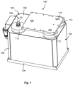
- Fig. 1 shows a perspective view of a force measuring device in the form of a weighing device 100 with a housing 102, which has a base plate 104, a circumferential side wall 106 and an upper housing wall 108.
- a load plate 110 is mechanically connected to three support elements that are guided through the upper housing wall 108, wherein the support elements pass through the upper housing wall 108 without contact.
- the corresponding openings in the upper housing wall 108 or the annular gaps that are formed by the inner walls of the openings and the outer walls of the support elements that pass through them are each "sealed" by means of a labyrinth seal 112, whereby sealing in this case means that an annular gap with a meandering cross-section, which is formed by each labyrinth seal, prevents the ingress of water, dust and other particles.
- the passage of the support elements remains contactless and does not generate any force shunt.
- a socket device 114 is provided, via which the weighing device 100 can be supplied with electrical energy and via which a unidirectional or bidirectional communication connection can be established between the weighing device 101 and a higher-level unit, for example an external control unit (not shown).
- the housing 102 of the weighing device 100 is not designed to be explosion-proof. Nevertheless, the weighing device 100, as a whole, should be designed in such a way that it can be operated in an explosive atmosphere, taking the relevant regulations into account.
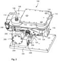
- Fig. 2 shows the weighing device 100 from Fig. 1 without the surrounding side wall of the housing 102.
- a force transducer 116 is provided inside this housing 102, which in the embodiment shown works according to the principle of electromagnetic force compensation.
- the force transducer 116 has a base body 118, which on the one hand comprises a base part 120 and on the other hand a load introduction area 122 connected to the base part 120 via a lever mechanism.
- the load introduction direction area 122 has a carrier plate 124 on its upper side, which in turn is connected to the support elements described above, which are guided through the upper housing wall 108 without contact.
- the carrier plate 124 can, for example, be screwed to the load introduction area 122.
- the force sensor 116 can thus detect the weight force acting on the load plate 110.
- the load plate 110 can be connected to and loaded by another device, for example a conveyor device (not shown), for example an electrically driven conveyor belt.
- the electrical drive of the conveyor belt must be supplied with electrical energy.
- a cable connection is usually used between the weighing device and the other device that is mechanically firmly connected to it.
- the term "cable connection" is used here. in the sense of any wired connection for the transmission of electrical currents (regardless of the purpose of the currents).
- Fig. 1 and 2 show a cable 126 of such a cable connection in part, wherein only the part of the cable 126 which passes through the upper housing wall 108 of the housing 102 of the weighing device 100 is shown.
- Fig. 2 shows a power transmission device 200 arranged in the interior of the housing 102, which has a housing 202.
- the housing 202 has a closure cover 204 provided on the front side wall, which is connected to the housing 202 with a plurality of screws.
- the housing 202 On its right side wall, the housing 202 has a cable feedthrough 206 fixed to the housing, wherein in Fig. 2 only a connecting part 208 connected to the housing is shown without a cable guided through the connecting part 208 and held in it.
- This cable guided into the housing 202 of the power transmission device 200 can be connected, for example, to the socket device 114, so that by connecting the socket device 114 a corresponding line connection can be established from an external unit (not shown) to the power transmission device 200 and from there to the unit connected to the load plate 110, for example a conveyor belt.
- the power transmission device 200 makes it possible to connect the cable (not shown) guided into the housing 202 on its side wall via the housing-fixed cable feedthrough 206 to the cable 126 in such a way that only a very small force shunt is caused with respect to the parts of the force transducer 116 (and thus also of the weighing device 100) that are movable relative to one another.
- Fig. 3 shows a sectional view of the power transmission device 200 in a (related to the illustration in Fig. 2 ) vertical center plane.
- the housing 202 has very thick walls, which ensure the pressure resistance of the housing.
- the connecting part 208 of the cable feedthrough 206 fixed to the housing is screwed into the right side wall of the housing, whereby this screw connection must of course also be designed to be pressure-resistant. in order to avoid the connecting part 208 being hurled away from the housing 202 like a projectile in the event of an explosion within the housing 202.
- the cable (not shown) which is led through the connecting part 208 must be connected to the connecting part 208 in such a way that it is at least ignition-tight.
- this can be done by a clamping mechanism (not shown in detail) or by gluing or casting. Since the cable usually has several lines combined in it, the sheath in an axially inner region of the connecting part 208 can also be removed to improve the connection between the cable and the connecting part 208, so that the individual lines can each be connected to the connecting part 208 individually, for example by gluing or casting.
- a housing-fixed contact device 210 is also arranged, which can be fixed, for example, by means of two screws 212 (in Fig. 2 only the left screw 212 is shown) can be screwed to the housing.
- the housing-fixed contact device 210 has connection contacts 210a, which can be connected to the ends of the lines contained in the cable. This can be done by soldering or any clamping mechanism.
- a through-opening 214 is formed in the upper wall of the housing 202, through which a connecting element 216 extends.
- the connecting element 216 is guided through the through-opening 214 in a contactless and ignition-proof manner, at least in an operating state in which the connecting element 216 is connected to the movable part of the weighing device 100, in particular the carrier plate 124 and thus also the load plate 110.
- the cross section of the through-opening 214 is dimensioned in relation to the cross section of the connecting element 216 (in the area of the through-opening 214) such that in the operating state there is an ignition-proof annular gap between the inner wall of the through-opening 214 and the outer wall or the outer circumference of the connecting element 216.
- the operating state therefore naturally requires a sufficiently precise positioning of the connecting element 216 relative to the housing 202 and thus the access opening 214.
- the connecting element 216 can be cylindrical, in particular circularly cylindrical, at least in the area with which the connecting element 216 passes through the through-opening 214. This results in a simple structural design, since the through-opening 214 can be designed as a bore.
- the connecting element 216 can have a receiving region for a further connecting part 208, which can have the same structural design as the connecting part 208 of the contact device 210 fixed to the housing. This results in a simple structural design.
- this region of the connecting element 216 can also be designed in any other suitable manner.
- the connecting part 208 is held in the connecting element 216 in a pressure-tight manner.
- the connecting element 216 is designed as a cable passage and for this purpose has a recess 218 which extends through the connecting element 216 over its entire length, wherein the upper region of the recess 218 is designed to receive the connecting part 208 with an internal thread which cooperates with an external thread of the connecting part 208.
- the connecting part 208 which is screwed into the upper part of the connecting element 216, receives a cable 220 of the cable connection 126 ( Fig. 2 ) and guides it into the recess 218 in a manner that is at least safe from ignition.
- the cable 220 can also have several lines, which can also be individually fixed in the connecting part 208, as described above.
- the cable 220 or the relevant lines are guided through the recess 218 and protrude with their inner ends into the interior of the housing 202.
- the inner area of the connecting element 216 also protrudes into the interior of the housing 202, so that, as can be seen from Fig. 3
- a movable contact device 222 can be attached to the inner end of the connecting part 216. This attachment can also be carried out by means of screws 224.
- the movable contact device 222 also has connection contacts 222a, which are connected to the ends of the at least one line (not shown) contained in the cable 220.
- the connection can again be made, for example, by soldering or suitable clamping mechanisms.
- the movable contact device 222 is thus movable together with the connecting element 216, whereby relative movements can be carried out with respect to the housing 202.
- the movement path depends on the design of the force transducer 116. If this is designed as a force transducer according to the principle of electromechanical force compensation, then at most infinitesimally small movement paths have to be carried out, since this measuring principle is based on keeping the load receptor in a predefined position if possible, whereby the current required for this represents a measure of the weight force to be measured.
- connection contacts 210a of the housing-fixed contact device 210 and the connection contacts 222a of the movable contact device 222 are connected via contact bridges 226, with a contact bridge 226 connecting a connection contact 210a to an associated connection contact 222a. Accordingly, a line of the cable guided into the housing 202 by means of the cable feedthrough 206 is connected to an associated line of the cable guided into the housing 202 by means of the connecting element 216.
- the contact bridges 226 consist of very flexible electrical conductors, for example gold wires or gold strips, in order to reduce a force shunt as much as possible. These can be connected to the connection contacts 222a or 210a by bonding, soldering or the like. If a contact bridge 226 is to be designed to carry higher current intensities, two or more wires can also be connected to the relevant connection contacts.
- connection devices 210 and 222 can, as in Fig. 3 shown, be designed as printed circuit boards, wherein the connection contacts 210a and 222a can be designed in the form of corresponding conductor tracks or conductor track areas. Connection contacts 210a and 222a can also each have start areas and end areas, which can be connected via one or more conductor tracks. Thus, the areas in which the ends of the contact bridges are connected to the connection contacts can be located at a different location than the areas of the Connection contacts that are connected to the corresponding ends of the wires in the cables.
- the circuit boards of the contact devices 210 and 222 are still connected to one another via connecting webs 228.
- the circuit boards of the contact devices were manufactured in this embodiment as a single circuit board which has a first area which forms the contact device 210 and a second area which forms the contact device 222.
- the still one-piece circuit board which forms the contact devices 210 and 222 can first be inserted into the housing 202 and fastened with the screws 212. The ends of the lines of the cable which is led into the housing by means of the cable feedthrough 206 can then be connected to the connection contacts 210a.
- the connecting element 216 can then be inserted into the through-opening 214 until the inner end of the connecting element 216 is positioned opposite the circuit board so that the circuit board can be connected to the connecting element 216 using the screws 224. In this state, the cable 220 does not yet have to be screwed into the upper area of the connecting element 216 together with the connecting part 208. However, this can also be the case.
- a ring-shaped mounting element 230 is provided on the connecting element 216, which surrounds the connecting element and can be moved axially (in the direction of a longitudinal axis L of the connecting element) on the connecting element 216.
- the mounting element 230 surrounds the connecting element 216 without play but axially displaceable, so that when the mounting element 230 is fixed, the connecting element 216 guided therein is also positioned exactly in the relevant position.
- the housing 202 has an engagement region 232 in the region of the access opening 214 on the upper housing wall, which engagement region is designed such that it interacts with a lower region of the mounting element 230 for an exact positioning of the mounting element 230 and thus of the connecting element 216.
- the engagement region 232 can, for example, have a circumferential annular shoulder 234 which has a vertically running inner wall which interacts with the vertical outer wall of the lower region of the mounting element 230.
- This outer wall in the lower region of the mounting element 230 and the inner wall of the annular shoulder 234 can be designed exactly coaxially to the longitudinal axis L.
- the annular shoulder or its (vertical) inner wall which runs coaxially to the longitudinal axis L can be designed in a region of the housing wall which protrudes relative to the surface of the upper housing wall and/or in a region of the housing wall which is offset inwards relative to the surface.
- an exact positioning of the connecting element 216 can be achieved by bringing the lower region of the mounting element 230 into engagement with the engagement region 232.
- the mounting element 230 can also be designed to be lockable relative to the connecting element 216, for example by means of one or more grub screws 236 which extend inwards in the wall of the mounting element 230 in the direction of the connecting element 216, perpendicular to the longitudinal axis L.
- the above-described assembly of the power transmission device 200 can be supplemented as follows: After connecting the circuit board forming the contact devices 210 and 222 to the connecting element 216, the Mounting element 230 can be pushed down into the engagement area 232 and locked in this position. The connecting webs 228 can then be separated and the closure cover 204 inserted and screwed to the housing 202. Pre-assembled in this way, the power transmission device 200 can be stored, packaged or installed in a weighing device 100.
- the power transmission device 200 can be provided at any suitable position within the housing 102, for example near the attachment point of the force transducer on the base plate 104 or near the load introduction area 122 or in the area of a rotary joint of a lever mechanism of the force transducer 116.
- the mounting element 230 can form a labyrinth seal 238 together with the engagement region 232.
- the lower end face of the mounting element 230 can act as a boundary wall for the labyrinth seal 238.
- the mounting element 230 can be surrounded by a ring element 240, which also contributes to the formation of the labyrinth seal 238.
- the ring element 240 has an inner cross section which essentially corresponds to the outer cross section of the mounting element 230, so that the ring element 240 essentially tightly encloses the mounting element 230.
- the ring element can also be fixed to the mounting element 230 by means of a grub screw 236.
- the mounting element 230 can have two recesses 242 into which the grub screw 236 in the ring element 240 can engage. A first recess 242, which in Fig.
- the ring element 240 can serve to lock the ring element 240 in an upwardly pushed state on the mounting element 230 so that the connecting element 230 can engage in the input area 232.
- a downwardly pushed state as in Fig. 4
- the grub screw 236 in the ring element 240 engages in a further recess in the mounting element 230 in order to fix the ring element in a downwards pushed position on the connecting element 216.
- the lower end face of the ring element 240 facing the upper housing wall can also act as a limit stop in order to limit an axial movement of the connecting element 216 into the housing 202.
- Such a limitation of the displacement path for the connecting element 216 can also be achieved by the closure cover 204 having a flange 204a which projects essentially horizontally into the housing interior and which engages in a groove 244 of the connecting element provided in the circumference of the area extending into the housing interior.
- the horizontally extending surfaces of the groove 244 have an axial distance which, based on the thickness of the flange 204a, is selected such that the connecting element 216 can carry out a sufficiently large axial displacement movement.
- the installation of the power transmission device 200 in a force measuring device can be carried out as described below:
- the pre-assembled power transmission device 200 as explained above is connected to the stationary area of the weighing device 100 by means of the mounting element 230 engaging in the engagement area 234 (in an adjusted and possibly locked state of the power transmission device 200).
- the housing 202 can be connected to the base plate 104 of the housing 102 of the weighing device 100. This can be done, for example, by screwing or the like.
- an upper head region of the connecting element 216 which is essentially circular-cylindrical in shape, has two surfaces 246 running parallel to one another in a suitable axial region. With this axial region, the head region of the connecting element 216 engage in a slot of a fork-shaped area in the carrier plate 124. A nut 248 can then be screwed onto the upper head area of the connecting element in order to mechanically connect the connecting element 216 firmly to the carrier plate 124.
- the upper housing wall 108 of the housing 102 can then be placed on top, with the upper area of the connecting element 216 and three further elements extending upwards from the carrier plate 124 reaching through the upper housing wall 108.
- the labyrinth seals 112 can then be produced both in the area where the upper area of the connecting element 216 reaches through the upper housing wall 108 and in the area of the other elements, and the load plate 110 can be mounted.
- the further device for example the conveyor belt
- the cable 220 can be connected to an electrical device of the further device, for example the drive of the conveyor belt.
- the assembly element 230 can be pushed into its upper position and locked in this position.
- the ring element 240 can be brought into its lower position and locked in this position.
- the cable that is led out of the housing 202 of the power transmission device 200 by means of the housing-fixed cable feedthrough 206 can be connected to the socket device 114. After the housing side wall has been attached, the assembly process is complete.
- the housing 102 can also be designed as a slip-on housing, i.e. the upper housing wall 108 and the side wall 106 are formed in one piece.
- the modular power transmission device 200 can thus be easily retrofitted to existing force measuring devices by making minor changes in order to make the force measuring device in question explosion-proof or to provide explosion protection.
- the modular design allows one and the same Power transmission device 200 can also be used for a wide variety of types of force measuring devices.
- the entire power transmission device 200 can also be arranged outside the housing of a force measuring device, for example on the same base frame or connected to the housing of the force measuring device.
Landscapes
- Physics & Mathematics (AREA)
- General Physics & Mathematics (AREA)
- Arrangements For Transmission Of Measured Signals (AREA)
- Measuring Fluid Pressure (AREA)
Applications Claiming Priority (1)
| Application Number | Priority Date | Filing Date | Title |
|---|---|---|---|
| DE102023111325.9A DE102023111325B3 (de) | 2023-05-02 | 2023-05-02 | Stromübertragungseinrichtung für eine Kraftmessvorrichtung, insbesondere eine Wägevorrichtung |
Publications (3)
| Publication Number | Publication Date |
|---|---|
| EP4459247A1 true EP4459247A1 (fr) | 2024-11-06 |
| EP4459247C0 EP4459247C0 (fr) | 2025-06-25 |
| EP4459247B1 EP4459247B1 (fr) | 2025-06-25 |
Family
ID=90482133
Family Applications (1)
| Application Number | Title | Priority Date | Filing Date |
|---|---|---|---|
| EP24166213.9A Active EP4459247B1 (fr) | 2023-05-02 | 2024-03-26 | Dispositif de transmission de courant pour un dispositif de mesure de force, en particulier un dispositif de pesée |
Country Status (6)
| Country | Link |
|---|---|
| US (1) | US20240369400A1 (fr) |
| EP (1) | EP4459247B1 (fr) |
| JP (1) | JP7699691B2 (fr) |
| CN (1) | CN118408661A (fr) |
| DE (1) | DE102023111325B3 (fr) |
| PL (1) | PL4459247T3 (fr) |
Citations (3)
| Publication number | Priority date | Publication date | Assignee | Title |
|---|---|---|---|---|
| JP3771994B2 (ja) * | 1997-06-10 | 2006-05-10 | 株式会社エー・アンド・デイ | 耐圧防爆型ロードセル |
| WO2013125418A1 (fr) * | 2012-02-22 | 2013-08-29 | 株式会社クボタ | Dispositif de cellule dynamométrique antidéflagrante |
| CN208488149U (zh) * | 2018-07-20 | 2019-02-12 | 常州市威博称重设备系统有限公司 | 一种防爆称重显示仪、防爆称重系统 |
Family Cites Families (7)
| Publication number | Priority date | Publication date | Assignee | Title |
|---|---|---|---|---|
| DE3722680A1 (de) * | 1987-07-09 | 1989-01-19 | Leybold Ag | Umschmelzofen mit gewichtsabhaengiger steuerung des abschmelzblocks |
| DE3904714A1 (de) * | 1989-02-16 | 1990-08-23 | Erich Brosa | Kraftmessring |
| DE102005055753B4 (de) * | 2005-11-21 | 2007-10-11 | Wipotec Wiege- Und Positioniersysteme Gmbh | Wägezelle für bewegte Güter |
| DE102008029900B4 (de) * | 2008-06-24 | 2010-10-14 | Ika-Werke Gmbh & Co. Kg | Laborreaktor mit einem Reaktionsgefäß |
| JP5164736B2 (ja) * | 2008-08-19 | 2013-03-21 | 大和製衡株式会社 | ロードセル |
| PL2216635T3 (pl) * | 2009-02-06 | 2019-12-31 | Mettler-Toledo Gmbh | Urządzenie kalibrujące dla urządzenia do pomiaru siły i urządzenie do pomiaru siły |
| DE102009011949B3 (de) * | 2009-03-10 | 2010-07-29 | Hottinger Baldwin Messtechnik Gmbh | Vorrichtung zur gewichtsabhängigen Befüllung von Behältern |
-
2023
- 2023-05-02 DE DE102023111325.9A patent/DE102023111325B3/de active Active
-
2024
- 2024-03-26 PL PL24166213.9T patent/PL4459247T3/pl unknown
- 2024-03-26 EP EP24166213.9A patent/EP4459247B1/fr active Active
- 2024-04-16 JP JP2024065983A patent/JP7699691B2/ja active Active
- 2024-04-28 CN CN202410521835.5A patent/CN118408661A/zh active Pending
- 2024-05-01 US US18/651,883 patent/US20240369400A1/en active Pending
Patent Citations (3)
| Publication number | Priority date | Publication date | Assignee | Title |
|---|---|---|---|---|
| JP3771994B2 (ja) * | 1997-06-10 | 2006-05-10 | 株式会社エー・アンド・デイ | 耐圧防爆型ロードセル |
| WO2013125418A1 (fr) * | 2012-02-22 | 2013-08-29 | 株式会社クボタ | Dispositif de cellule dynamométrique antidéflagrante |
| CN208488149U (zh) * | 2018-07-20 | 2019-02-12 | 常州市威博称重设备系统有限公司 | 一种防爆称重显示仪、防爆称重系统 |
Also Published As
| Publication number | Publication date |
|---|---|
| US20240369400A1 (en) | 2024-11-07 |
| EP4459247C0 (fr) | 2025-06-25 |
| DE102023111325B3 (de) | 2024-05-08 |
| JP7699691B2 (ja) | 2025-06-27 |
| CN118408661A (zh) | 2024-07-30 |
| PL4459247T3 (pl) | 2025-10-06 |
| JP2024160947A (ja) | 2024-11-15 |
| EP4459247B1 (fr) | 2025-06-25 |
Similar Documents
| Publication | Publication Date | Title |
|---|---|---|
| DE69513436T2 (de) | Schaltgerätmodul und Konfigurationen | |
| DE102018213522B4 (de) | Schmelzsicherung, Sicherungskörper, System und Verfahren | |
| EP1835264B1 (fr) | Appareil de mesure alimenté directement sans sécurité intrinsèque | |
| DE102016108840B4 (de) | Vorrichtung zur Temperaturregelung und Verfahren zur Herstellung einer Vorrichtung zur Temperaturregelung | |
| EP0825447B1 (fr) | Appareil de mesure pour une installation blindée à haute tension à isolation de gaz | |
| EP3546895A1 (fr) | Dispositif et procédé de fonctionnement d'un capteur chauffant, en particulier dans une atmosphère explosive | |
| EP3741011B1 (fr) | Dispositif de protection pour ensemble de raccordement par enfichage | |
| DE3610742A1 (de) | Stuetzisolator | |
| DE19746566A1 (de) | Kurzschließer, insbesondere für eine Störlichtbogen-Schutzvorrichtung zur Verwendung in Anlagen zur Verteilung elektrischer Energie | |
| DE2900329A1 (de) | Explosionsgeschuetzte schalteinrichtung | |
| EP0237776A2 (fr) | Interrupteur à haute tension | |
| DE102023111325B3 (de) | Stromübertragungseinrichtung für eine Kraftmessvorrichtung, insbesondere eine Wägevorrichtung | |
| EP1048100A1 (fr) | Court-circuiteur, notamment pour dispositif de protection contre les arcs de lumiere parasite, utilise dans des systemes de repartition d'energie electrique | |
| EP2774162B1 (fr) | Disjoncteur doté d'une mesure de tension interne | |
| EP1052665B1 (fr) | Court-circuiteur | |
| DE9420199U1 (de) | Metallgekapselte Hochspannungsschaltanlage | |
| DE69508055T2 (de) | Apparat mit unterdrückung von transienten spannungen | |
| DE19746815A1 (de) | Kurzschließer, insbesondere für eine Störlichtbogen-Schutzvorrichtung zur Verwendung in Anlagen zur Verteilung elektrischer Energie | |
| WO2018001863A1 (fr) | Transducteur de mesure pour les techniques de mesure haute tension | |
| DE102011052449A1 (de) | Stromwandler sowie Lasttrenner mit einem solchen | |
| DE102022130669A1 (de) | Einschraubbares Verbindungselement zur Ex-i und Ex-d konformen Durchführung von elektrischen Signalen | |
| DE19746813A1 (de) | Verfahren zur Montage von Kurzschließern für Störlichtbogen-Schutzvorrichtungen zur Verwendung in Anlagen zur Verteilung elektrischer Energie | |
| EP2466706A2 (fr) | Armoire électrique pour le fonctionnement d'une installation de commutation à moyenne ou haute tension | |
| DE3012743C2 (de) | Gerät der Schutzart Eigensicherheit | |
| DE112018007318B4 (de) | Betriebsmittel mit auswechselbarem Anschlusselement und Prozessventilbaueinheit |
Legal Events
| Date | Code | Title | Description |
|---|---|---|---|
| PUAI | Public reference made under article 153(3) epc to a published international application that has entered the european phase |
Free format text: ORIGINAL CODE: 0009012 |
|
| STAA | Information on the status of an ep patent application or granted ep patent |
Free format text: STATUS: THE APPLICATION HAS BEEN PUBLISHED |
|
| AK | Designated contracting states |
Kind code of ref document: A1 Designated state(s): AL AT BE BG CH CY CZ DE DK EE ES FI FR GB GR HR HU IE IS IT LI LT LU LV MC ME MK MT NL NO PL PT RO RS SE SI SK SM TR |
|
| STAA | Information on the status of an ep patent application or granted ep patent |
Free format text: STATUS: REQUEST FOR EXAMINATION WAS MADE |
|
| 17P | Request for examination filed |
Effective date: 20241202 |
|
| RBV | Designated contracting states (corrected) |
Designated state(s): AL AT BE BG CH CY CZ DE DK EE ES FI FR GB GR HR HU IE IS IT LI LT LU LV MC ME MK MT NL NO PL PT RO RS SE SI SK SM TR |
|
| GRAP | Despatch of communication of intention to grant a patent |
Free format text: ORIGINAL CODE: EPIDOSNIGR1 |
|
| STAA | Information on the status of an ep patent application or granted ep patent |
Free format text: STATUS: GRANT OF PATENT IS INTENDED |
|
| INTG | Intention to grant announced |
Effective date: 20250127 |
|
| GRAS | Grant fee paid |
Free format text: ORIGINAL CODE: EPIDOSNIGR3 |
|
| GRAA | (expected) grant |
Free format text: ORIGINAL CODE: 0009210 |
|
| STAA | Information on the status of an ep patent application or granted ep patent |
Free format text: STATUS: THE PATENT HAS BEEN GRANTED |
|
| AK | Designated contracting states |
Kind code of ref document: B1 Designated state(s): AL AT BE BG CH CY CZ DE DK EE ES FI FR GB GR HR HU IE IS IT LI LT LU LV MC ME MK MT NL NO PL PT RO RS SE SI SK SM TR |
|
| REG | Reference to a national code |
Ref country code: GB Ref legal event code: FG4D Free format text: NOT ENGLISH |
|
| REG | Reference to a national code |
Ref country code: CH Ref legal event code: EP |
|
| REG | Reference to a national code |
Ref country code: CH Ref legal event code: EP |
|
| REG | Reference to a national code |
Ref country code: IE Ref legal event code: FG4D Free format text: LANGUAGE OF EP DOCUMENT: GERMAN |
|
| REG | Reference to a national code |
Ref country code: DE Ref legal event code: R096 Ref document number: 502024000080 Country of ref document: DE |
|
| U01 | Request for unitary effect filed |
Effective date: 20250722 |
|
| U07 | Unitary effect registered |
Designated state(s): AT BE BG DE DK EE FI FR IT LT LU LV MT NL PT RO SE SI Effective date: 20250728 |
|
| PG25 | Lapsed in a contracting state [announced via postgrant information from national office to epo] |
Ref country code: GR Free format text: LAPSE BECAUSE OF FAILURE TO SUBMIT A TRANSLATION OF THE DESCRIPTION OR TO PAY THE FEE WITHIN THE PRESCRIBED TIME-LIMIT Effective date: 20250926 Ref country code: NO Free format text: LAPSE BECAUSE OF FAILURE TO SUBMIT A TRANSLATION OF THE DESCRIPTION OR TO PAY THE FEE WITHIN THE PRESCRIBED TIME-LIMIT Effective date: 20250925 |
|
| PG25 | Lapsed in a contracting state [announced via postgrant information from national office to epo] |
Ref country code: HR Free format text: LAPSE BECAUSE OF FAILURE TO SUBMIT A TRANSLATION OF THE DESCRIPTION OR TO PAY THE FEE WITHIN THE PRESCRIBED TIME-LIMIT Effective date: 20250625 |
|
| PG25 | Lapsed in a contracting state [announced via postgrant information from national office to epo] |
Ref country code: RS Free format text: LAPSE BECAUSE OF FAILURE TO SUBMIT A TRANSLATION OF THE DESCRIPTION OR TO PAY THE FEE WITHIN THE PRESCRIBED TIME-LIMIT Effective date: 20250925 |
|
| PG25 | Lapsed in a contracting state [announced via postgrant information from national office to epo] |
Ref country code: IS Free format text: LAPSE BECAUSE OF FAILURE TO SUBMIT A TRANSLATION OF THE DESCRIPTION OR TO PAY THE FEE WITHIN THE PRESCRIBED TIME-LIMIT Effective date: 20251025 |
|
| PG25 | Lapsed in a contracting state [announced via postgrant information from national office to epo] |
Ref country code: SM Free format text: LAPSE BECAUSE OF FAILURE TO SUBMIT A TRANSLATION OF THE DESCRIPTION OR TO PAY THE FEE WITHIN THE PRESCRIBED TIME-LIMIT Effective date: 20250625 |
|
| PG25 | Lapsed in a contracting state [announced via postgrant information from national office to epo] |
Ref country code: CZ Free format text: LAPSE BECAUSE OF FAILURE TO SUBMIT A TRANSLATION OF THE DESCRIPTION OR TO PAY THE FEE WITHIN THE PRESCRIBED TIME-LIMIT Effective date: 20250625 |
|
| PG25 | Lapsed in a contracting state [announced via postgrant information from national office to epo] |
Ref country code: SK Free format text: LAPSE BECAUSE OF FAILURE TO SUBMIT A TRANSLATION OF THE DESCRIPTION OR TO PAY THE FEE WITHIN THE PRESCRIBED TIME-LIMIT Effective date: 20250625 |
|
| PG25 | Lapsed in a contracting state [announced via postgrant information from national office to epo] |
Ref country code: ES Free format text: LAPSE BECAUSE OF FAILURE TO SUBMIT A TRANSLATION OF THE DESCRIPTION OR TO PAY THE FEE WITHIN THE PRESCRIBED TIME-LIMIT Effective date: 20250625 |
|
| U20 | Renewal fee for the european patent with unitary effect paid |
Year of fee payment: 3 Effective date: 20260221 |
|
| PGFP | Annual fee paid to national office [announced via postgrant information from national office to epo] |
Ref country code: TR Payment date: 20260325 Year of fee payment: 3 |
|
| PGFP | Annual fee paid to national office [announced via postgrant information from national office to epo] |
Ref country code: PL Payment date: 20260317 Year of fee payment: 3 |
|
| PLBE | No opposition filed within time limit |
Free format text: ORIGINAL CODE: 0009261 |
|
| STAA | Information on the status of an ep patent application or granted ep patent |
Free format text: STATUS: NO OPPOSITION FILED WITHIN TIME LIMIT |