EP4459334A1 - Dispositif d'inspection par balayage - Google Patents
Dispositif d'inspection par balayage Download PDFInfo
- Publication number
- EP4459334A1 EP4459334A1 EP22914868.9A EP22914868A EP4459334A1 EP 4459334 A1 EP4459334 A1 EP 4459334A1 EP 22914868 A EP22914868 A EP 22914868A EP 4459334 A1 EP4459334 A1 EP 4459334A1
- Authority
- EP
- European Patent Office
- Prior art keywords
- rotating frame
- stator
- pipe section
- rotor
- drive
- Prior art date
- Legal status (The legal status is an assumption and is not a legal conclusion. Google has not performed a legal analysis and makes no representation as to the accuracy of the status listed.)
- Pending
Links
Images


Classifications
-
- G—PHYSICS
- G01—MEASURING; TESTING
- G01V—GEOPHYSICS; GRAVITATIONAL MEASUREMENTS; DETECTING MASSES OR OBJECTS; TAGS
- G01V5/00—Prospecting or detecting by the use of ionising radiation, e.g. of natural or induced radioactivity
-
- A—HUMAN NECESSITIES
- A61—MEDICAL OR VETERINARY SCIENCE; HYGIENE
- A61B—DIAGNOSIS; SURGERY; IDENTIFICATION
- A61B6/00—Apparatus or devices for radiation diagnosis; Apparatus or devices for radiation diagnosis combined with radiation therapy equipment
- A61B6/02—Arrangements for diagnosis sequentially in different planes; Stereoscopic radiation diagnosis
- A61B6/03—Computed tomography [CT]
-
- A—HUMAN NECESSITIES
- A61—MEDICAL OR VETERINARY SCIENCE; HYGIENE
- A61B—DIAGNOSIS; SURGERY; IDENTIFICATION
- A61B6/00—Apparatus or devices for radiation diagnosis; Apparatus or devices for radiation diagnosis combined with radiation therapy equipment
- A61B6/02—Arrangements for diagnosis sequentially in different planes; Stereoscopic radiation diagnosis
- A61B6/03—Computed tomography [CT]
- A61B6/032—Transmission computed tomography [CT]
- A61B6/035—Mechanical aspects of CT
-
- A—HUMAN NECESSITIES
- A61—MEDICAL OR VETERINARY SCIENCE; HYGIENE
- A61B—DIAGNOSIS; SURGERY; IDENTIFICATION
- A61B6/00—Apparatus or devices for radiation diagnosis; Apparatus or devices for radiation diagnosis combined with radiation therapy equipment
- A61B6/44—Constructional features of apparatus for radiation diagnosis
- A61B6/4488—Means for cooling
-
- G—PHYSICS
- G01—MEASURING; TESTING
- G01N—INVESTIGATING OR ANALYSING MATERIALS BY DETERMINING THEIR CHEMICAL OR PHYSICAL PROPERTIES
- G01N23/00—Investigating or analysing materials by the use of wave or particle radiation, e.g. X-rays or neutrons, not covered by groups G01N3/00 – G01N17/00, G01N21/00 or G01N22/00
- G01N23/02—Investigating or analysing materials by the use of wave or particle radiation, e.g. X-rays or neutrons, not covered by groups G01N3/00 – G01N17/00, G01N21/00 or G01N22/00 by transmitting the radiation through the material
- G01N23/04—Investigating or analysing materials by the use of wave or particle radiation, e.g. X-rays or neutrons, not covered by groups G01N3/00 – G01N17/00, G01N21/00 or G01N22/00 by transmitting the radiation through the material and forming images of the material
-
- G—PHYSICS
- G01—MEASURING; TESTING
- G01N—INVESTIGATING OR ANALYSING MATERIALS BY DETERMINING THEIR CHEMICAL OR PHYSICAL PROPERTIES
- G01N23/00—Investigating or analysing materials by the use of wave or particle radiation, e.g. X-rays or neutrons, not covered by groups G01N3/00 – G01N17/00, G01N21/00 or G01N22/00
- G01N23/02—Investigating or analysing materials by the use of wave or particle radiation, e.g. X-rays or neutrons, not covered by groups G01N3/00 – G01N17/00, G01N21/00 or G01N22/00 by transmitting the radiation through the material
- G01N23/04—Investigating or analysing materials by the use of wave or particle radiation, e.g. X-rays or neutrons, not covered by groups G01N3/00 – G01N17/00, G01N21/00 or G01N22/00 by transmitting the radiation through the material and forming images of the material
- G01N23/046—Investigating or analysing materials by the use of wave or particle radiation, e.g. X-rays or neutrons, not covered by groups G01N3/00 – G01N17/00, G01N21/00 or G01N22/00 by transmitting the radiation through the material and forming images of the material using tomography, e.g. computed tomography [CT]
-
- G—PHYSICS
- G01—MEASURING; TESTING
- G01V—GEOPHYSICS; GRAVITATIONAL MEASUREMENTS; DETECTING MASSES OR OBJECTS; TAGS
- G01V5/00—Prospecting or detecting by the use of ionising radiation, e.g. of natural or induced radioactivity
- G01V5/20—Detecting prohibited goods, e.g. weapons, explosives, hazardous substances, contraband or smuggled objects
-
- G—PHYSICS
- G01—MEASURING; TESTING
- G01N—INVESTIGATING OR ANALYSING MATERIALS BY DETERMINING THEIR CHEMICAL OR PHYSICAL PROPERTIES
- G01N2223/00—Investigating materials by wave or particle radiation
- G01N2223/30—Accessories, mechanical or electrical features
- G01N2223/308—Accessories, mechanical or electrical features support of radiation source
-
- G—PHYSICS
- G01—MEASURING; TESTING
- G01N—INVESTIGATING OR ANALYSING MATERIALS BY DETERMINING THEIR CHEMICAL OR PHYSICAL PROPERTIES
- G01N2223/00—Investigating materials by wave or particle radiation
- G01N2223/30—Accessories, mechanical or electrical features
- G01N2223/31—Accessories, mechanical or electrical features temperature control
- G01N2223/3103—Accessories, mechanical or electrical features temperature control cooling, cryostats
-
- G—PHYSICS
- G01—MEASURING; TESTING
- G01N—INVESTIGATING OR ANALYSING MATERIALS BY DETERMINING THEIR CHEMICAL OR PHYSICAL PROPERTIES
- G01N2223/00—Investigating materials by wave or particle radiation
- G01N2223/30—Accessories, mechanical or electrical features
- G01N2223/33—Accessories, mechanical or electrical features scanning, i.e. relative motion for measurement of successive object-parts
- G01N2223/3303—Accessories, mechanical or electrical features scanning, i.e. relative motion for measurement of successive object-parts object fixed; source and detector move
-
- G—PHYSICS
- G01—MEASURING; TESTING
- G01N—INVESTIGATING OR ANALYSING MATERIALS BY DETERMINING THEIR CHEMICAL OR PHYSICAL PROPERTIES
- G01N2223/00—Investigating materials by wave or particle radiation
- G01N2223/60—Specific applications or type of materials
- G01N2223/643—Specific applications or type of materials object on conveyor
Definitions
- the present disclosure relates to the technical field of security inspection, in particular to a scanning inspection device.
- a system uses an intensity change of a high-energy X-ray generated by a ray source after passing through an object to be inspected to reflect the distribution of density of the object to be inspected, and converts the intensity change of the ray into an image gray scale to obtain a transmission image.
- a system uses an intensity change of a high-energy X-ray generated by a ray source after passing through an object to be inspected to reflect the distribution of density of the object to be inspected, and converts the intensity change of the ray into an image gray scale to obtain a transmission image.
- a container inspection system with a CT (Computed Tomography) scanning function in the related art.
- the system can perform tomography scanning on a suspicious part of an object to be inspected and reconstruct a two-dimensional image of an inspected cross-section.
- This type of inspection system can implement continuous rotational scanning, and thus can reconstruct an object to be inspected in three dimensions and provide more information.
- a ray source has high energy and generates a large amount of heat, it is liable to cause damage to the ray source itself and neighboring components, and result in failure of the ray source and the neighboring components, which affects normal working of the inspection system. How to cool the ray source has become a major problem to be solved urgently.
- Embodiments of the present disclosure provide a scanning inspection device capable of cooling a ray source in a timely and effective manner.
- a scanning inspection device which includes:
- the cooling device is disposed outside a scanning range of the ray source.
- the scanning inspection device further includes a second rotating frame, the second rotating frame being mounted on the first rotating frame, the cooling device being mounted on the second rotating frame, and the second drive device being in drive connection with the second rotating frame to drive the second rotating frame to rotate relative to the first rotating frame.
- the cooling device includes a refrigerating device and a first conveying pipe, the first conveying pipe being in communication with the refrigerating device and configured to convey a heat exchange medium from the refrigerating device to the ray source for cooling thereof.
- the cooling device further includes a second conveying pipe, the second conveying pipe being connected between an outlet of the first conveying pipe and the refrigerating device to return the heat exchange medium after heat exchange with the ray source to the refrigerating device.
- the scanning inspection device further includes a rotary joint, which includes a first stator and a first rotor rotationally connected to the first stator, the first stator being connected to the first rotating frame, and the first rotor being connected to the second rotating frame; and the first conveying pipe includes a first pipe section and a second pipe section, the first pipe section being connected between the refrigeration device and the first stator, and the second pipe section being connected to the first rotor, and the first pipe section and the second pipe section being in fluid communication through a first fluid pass age between the first stator and the first rotor.
- the scanning inspection device further includes a rotary joint, which includes a first stator and a first rotor rotationally connected to the first stator, the first stator being connected to the first rotating frame, and the first rotor being connected to the second rotating frame;
- the first conveying pipe includes a first pipe section and a second pipe section, the first pipe section being connected between the refrigeration device and the first stator, and the second pipe section being connected to the first rotor, and the first pipe section and the second pipe section being in fluid communication through a first fluid passage between the first stator and the first rotor;
- the second conveying pipe includes a third pipe section and a fourth pipe section, the third pipe section being connected between an outlet of the second pipe section and the first rotor, and the fourth pipe section being connected between the first stator and the refrigerating device, and the third pipe section and the fourth pipe section being in fluid communication through a second fluid passage between the first stator and the first rotor.
- the scanning inspection device further includes a first slip ring, a first cable and a second cable
- the first slip ring includes a second stator and a second rotor rotationally connected to the second stator, the second stator being connected to the first rotating frame, and the second rotor being connected to the second rotating frame
- the first cable is connected between the power supply source and the second stator
- the second cable is connected between the second rotor and an electrical socket of the refrigerating device
- electrical connection between the first cable and the second cable is implemented by an electrical connection circuit between the second stator and the second rotor
- an axis of rotation of the rotary joint, an axis of rotation of the first slip ring, and an axis of rotation of the second rotating frame relative to the first rotating frame are collinear.
- the first rotating frame includes a first support plate and a second support plate connected to the first support plate, wherein a preset distance is formed between the first support plate and the second support plate; the second rotating frame is disposed between the first support plate and the second support plate; the rotary joint is disposed between the second rotating frame and the first support plate; and the first slip ring is disposed between the second rotating frame and the second support plate.
- the scanning inspection device further includes a first support body, a second support body, a first slewing bearing, and a second slewing bearing, wherein the first support body is connected to the first support plate, and the first slewing bearing is supported on the first support body and connected to the second rotating frame; and the second support body is connected to the second support plate, and the second slewing bearing is supported on the second support body and connected to the second rotating frame.
- the first support body includes a first hollow cylinder, and the first stator is mounted in the first hollow cylinder; and/or the second support body includes a second hollow cylinder, and the second stator is mounted in the second hollow cylinder.
- an outer ring of the first slewing bearing and/or the second slewing bearing is provided with an outer tooth
- the second drive device includes a gear and a drive unit, the gear being engaged with the outer tooth, and the drive unit being configured to drive the gear to rotate.
- the scanning inspection device further includes a second slip ring, which is connected between the first cable and the power supply source, and an axis of rotation of the second slip ring is collinear with the axis of rotation of the first rotating frame.
- the scanning inspection device further includes a detection device configured to detect a rotation angle of the second rotating frame, and the second drive device is in signal connection with the detection device to adjust the rotation angle of the second rotating frame relative to the first rotating frame based on a detection result from the detection device.
- the detection device includes an encoder.
- the first rotating frame is also provided with a cooling device, which can cool the ray source in time and prevent failure or damage of the ray source caused by too much heat generated due to working for too long time; and the scanning inspection device also includes a second drive device, which can drive the cooling device to rotate toward a direction opposite to a rotation direction of the first rotating frame to maintain a relatively fixed attitude of the cooling device, and prevent dysfunction or failure of the cooling device due to tilting or inverting in the process of rotating with the first rotating frame, which is conducive to ensuring normal working of the cooling device in the process of rotation.
- orientation or position relations denoted by the terms “center”, “transverse”, “longitudinal”, “front”, “rear”, “left”, “right”, “upper”, “lower”, “vertical”, “horizontal”, “top”, “bottom”, “inner”, “outer” and the like are orientation or position relations illustrated based on the drawings, are merely for the convenience of describing the present disclosure and simplifying description, instead of indicating or implying the denoted devices or elements necessarily have specific orientations or be constructed and operated in specific orientations, and thus the terms cannot be understood as limiting the protection scope of the present disclosure.
- the inventors In order to cool a ray source in a rotating scanning inspection system, the inventors have made various attempts and found that the ray source rotates continuously during inspection, and if the cooling system is disposed in a fixed position, a connecting device between the cooling system and the ray source will be winded and twisted during rotation of the ray source, and a connecting cable will break and affect normal working of the scanning system after long time of rotation; and if the cooling system rotates together with the ray source, the cooling system will be tilted or inverted relative to the ground.
- the cooling system includes a compressor, and operation fault will occur in the compressor after tilting or inversion.
- the cooling system is simply configured to rotate with the ray source.
- a cooling system is configured to rotate together with a ray source while rotating around its axis relative to the ray source, which can effectively solve the problem of failure caused by tilting or inverting of the cooling system, and at the same time, can also achieve effective cooling of the ray source.
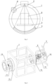
- the scanning inspection device includes a first rotating frame 1, a first drive device, a ray source 2, a detector 3, a second drive device, and a cooling device for cooling the ray source 2.
- a conveying channel for passage of an object to be inspected 6 is provided in the center of the first rotating frame 1.
- the first drive device is in drive connection with the first rotating frame 1 to drive the first rotating frame 1 to rotate.
- the ray source 2, the detector 3, and the cooling device for cooling the ray source 2 are each mounted on the first rotating frame 1 and rotate with the first rotating frame 1.
- the second drive device is configured to drive the cooling device to rotate toward a direction opposite to a rotation direction of the first rotating frame 1, so that the cooling device is maintained in a fixed attitude during rotation with the first rotating frame 1.
- the first rotating frame 1 by rotating the first rotating frame 1 to cause the ray source 2 and the detector 3 to rotate relative to the object to be inspected 6, 360° scanning inspection can be implemented on the object to be inspected 6, which improves the full coverage and reliability of scanning inspection; moreover, the first rotating frame 1 is also provided with a cooling device, which can cool the ray source in time and prevent failure or damage of the ray source caused by too much heat generated due to working for too long time; and the scanning inspection device also includes a second drive device, which can drive the cooling device to rotate toward a direction opposite to a rotation direction of the first rotating frame 1 to maintain a relatively fixed attitude of the cooling device, prevent the cooling device from tilting or inverting in the process of rotating with the first rotating frame 1, and ensure normal working of the cooling device in the process of rotation.
- a cooling device which can cool the ray source in time and prevent failure or damage of the ray source caused by too much heat generated due to working for too long time
- the scanning inspection device also includes a second drive device, which can drive the cooling device
- the first drive device drives the first rotating frame 1 to rotate relative to the ground, and the ray source 2, the detector 3, and the cooling device revolve with the first rotating frame 1, and at the same time the cooling device also rotates around its axis relative to the first rotating frame 1.
- the rotation direction of the cooling device around its axis is opposite to its revolution direction, to keep the cooling device relatively fixed with respect to the ground, such as keeping the cooling device vertical at all the time during the revolution, prevent the cooling device from tilting or inverting, and ensure normal working of the cooling device.
- the cooling device simultaneously rotates around its axis in the opposite direction, and the cooling device always maintains a relatively fixed attitude with respect to the ground without tilting.
- the ray source 2 and the detector 3 are spaced apart in a circumferential direction of the first rotating frame 1, and a ray emitted by the ray source 2 is irradiated on the object to be inspected 6 located in the conveying channel, and the ray is received by the detector 3 after passing through the object to be inspected 6, thereby achieving scanning inspection.
- a conveying device 5 is provided in the conveying channel, and the conveying device 5 is configured to convey the object to be inspected 6 to pass through the conveying channel, thereby accomplishing scanning inspection during the conveying process.
- the conveying device 5 may be a conveyor belt or a conveyor chain, or the like.
- the cooling device is disposed outside a scanning range of the ray source 2. Such configuration can avoid the cooling device's influence on the scanning inspection of the object to be inspected 6 and improve the accuracy of the scanning inspection.
- the scanning inspection device further includes a second rotating frame 7.
- the second rotating frame 7 is mounted on the first rotating frame 1
- the cooling device is mounted on the second rotating frame 7, and the second drive device is in drive connection with the second rotating frame 7 to drive the second rotating frame 7 to rotate relative to the first rotating frame 1.
- the cooling device can be caused to rotate around its axis by the rotation of the second rotating frame 7, the installation of the cooling device is facilitated, and direct connection between the cooling device and the second drive device can also be avoided, which is conducive to protecting the cooling device.
- the cooling device includes a refrigerating device 4 and a first conveying pipe 9.
- the first conveying pipe 9 is in communication with the refrigerating device 4 and configured to convey a heat exchange medium from the refrigerating device 4 to the ray source 2 to cool the ray source.
- a portion of the heat exchange medium is taken from the refrigeration device 4 to cool the ray source 2, and the heat exchange medium may absorb heat emitted by the ray source 2, to avoid damaging the ray source itself or neighboring components by the heat emitted by the ray source 2, and improve the service life of the ray source 2 and the neighboring components.
- the cooling device further includes a second conveying pipe 10.
- the second conveying pipe 10 is connected between an outlet of the first conveying pipe 9 and the refrigerating device 4 to return the heat exchange medium after heat exchange with the ray source 2 to the refrigerating device 4.
- the cooling device 4 By providing the second conveying pipe 10, the cooling device 4, the first conveying pipe 9 and the second conveying pipe 10 can form a closed-loop circuit to achieve continuous cooling of the ray source 2, and it can also simplify the structure of the cooling device, and reduce connections between the cooling device, and other components that do not rotate with the first rotating frame 1.
- the first conveying pipe 9 is wound around an outer periphery of the ray source 2, and the heat exchange medium in the first conveying pipe 9 exchanges heat with the ray source 2; or the first conveying pipe 9 is communicated with a cooling flow path inside the ray source 2, and the first conveying pipe 9 conveys the heat exchange medium to the interior of the ray source 2 to cool the ray source 2.
- the refrigerating device 4 includes a compressor, a condenser, and a throttling element, and a heat exchange section of the first conveying pipe 9 with the ray source 2 may act as an evaporator of the refrigerating device 4 to implement a refrigeration cycle.
- the heat exchange medium conveyed by the first conveying pipe 9 is a refrigerant.
- the refrigerating device 4 includes a compressor, a condenser, a throttling element, and an evaporator.
- the heat exchange medium conveyed by the first conveying pipe 9 undergoes heat exchange with the evaporator in the refrigerating device 4, and the cooled heat exchange medium is conveyed to the ray source 2 to cool the ray source 2.
- the heat exchange medium may be water, or the like.
- the ray source 2 rotates with the first rotating frame 1, and the cooling device rotates around itself while revolving, a rotary joint is used for connections in order to avoid winding and twisting of the first conveying pipe 9.
- the scanning inspection device further includes a rotary joint 8.
- the rotary joint 8 includes a first stator 81 and a first rotor 82 rotationally connected to the first stator 81.
- the first stator 81 is connected to the first rotating frame 1, and the first rotor 82 is connected to the second rotating frame 7.
- the first conveying pipe 9 includes a first pipe section 91 and a second pipe section 92.
- the first pipe section 91 is connected between the refrigeration device 4 and the first stator 81, and the second pipe section 92 is connected to the first rotor 82.
- the first pipe section 91 and the second pipe section 92 are in fluid communication through a first fluid passage between the first stator 81 and the first rotor 82.
- the second pipe section 92 can rotate relative to the first pipe section 91, which, on the basis of implementing conveying of the heat exchange medium, can also avoid winding of the first conveying pipe 9 due to rotation of the cooling device around its axis.
- the scanning inspection device further includes a second conveying pipe 10
- the scanning inspection device further includes a rotary joint 8.
- the rotary joint 8 includes a first stator 81 and a first rotor 82 rotationally connected to the first stator 81.
- the first stator 81 is connected to the first rotating frame 1, and the first rotor 82 is connected to the second rotating frame 7.
- the first conveying pipe 9 includes a first pipe section 91 and a second pipe section 92.
- the first pipe section 91 is connected between the refrigeration device 4 and the first stator 81, and the second pipe section 92 is connected to the first rotor 82.
- the first pipe section 91 and the second pipe section 92 are in fluid communication through a first fluid passage between the first stator 81 and the first rotor 82.
- the second conveying pipe 10 includes a third pipe section 101 and a fourth pipe section 102.
- the third pipe section 101 is connected between an outlet of the second pipe section 92 and the first rotor 82, and the fourth pipe section 102 is connected between the first stator 81 and the refrigerating device 4.
- the third pipe section 101 and the fourth pipe section 102 are in fluid communication through a second fluid passage between the first stator 81 and the first rotor 82.
- the number of the first conveying pipe 9 is two or more, and the number of the second conveying pipe 10 may also be two or more.
- the scanning inspection device further includes a first slip ring 11 and a connecting cable 12.
- the connecting cable 12 includes a first cable 121 and a second cable 122.
- the first slip ring 11 includes a second stator 111 and a second rotor 112 rotationally connected to the second stator 111.
- the second stator 111 is connected to the first rotating frame 1, and the second rotor 112 is connected to the second rotating frame 7.
- the first cable 121 is connected between the power supply source and the second stator 111, and the second cable 122 is connected between the second rotor 112 and an electrical socket of the refrigerating device 4.
- Electrical connection between the first cable 121 and the second cable 122 is implemented by an electrical connection circuit between the second stator 111 and the second rotor 112.
- An axis of rotation of the rotary joint 8, an axis of rotation of the first slip ring 11, and an axis of rotation of the second rotating frame 7 relative to the first rotating frame 1 are collinear.
- the second cable 122 may rotate relative to the first cable 121, to avoid the problem of winding of the connecting cable caused during rotation of the cooling device around its axis.
- the axis of rotation of the rotary joint 8 By setting the axis of rotation of the rotary joint 8, the axis of rotation of the first slip ring 11, and the axis of rotation of the second rotating frame 7 relative to the first rotating frame 1 to be collinear, it can avoid winding of the first conveying pipe 9, the second conveying pipe 10, and the connecting cable 12 while the cooling device rotates around its axis.
- the first rotating frame 1 includes a first support plate 1a and a second support plate 1b connected to the first support plate 1a.
- a preset distance is formed between the first support plate 1a and the second support plate 1b.
- the second rotating frame 7 is disposed between the first support plate 1a and the second support plate 1b.
- the rotary joint 8 is disposed between the second rotating frame 7 and the first support plate 1a.
- the first slip ring 11 is disposed between the second rotating frame 7 and the second support plate 1b.
- Such an arrangement facilitates achieving collinearity of the axis of rotation of the rotary joint 8, the axis of rotation of the first slip ring 11, and the axis of rotation of the second rotating frame 7 relative to the first rotating frame 1, and can also achieve relative independence of the heat exchange medium and the electrical connection, and avoid the intersection and mutual influence of the first conveying pipe 9, the second conveying pipe 10, and the connecting cable 12.
- the scanning inspection device further includes a first support body 13, a second support body 14, a first slewing bearing 15 and a second slewing bearing 16.
- the first support body 13 is connected to the first support plate 1a, and the first slewing bearing 15 is supported on the first support body 13 and connected to the second rotating frame 7.
- the second support body 14 is connected to the second support plate 1b, and the second slewing bearing 16 is supported on the second support body 14 and connected to the second rotating frame 7.
- the second rotating frame 7 can be supported, and sufficient space can also be retained for the arrangement of the rotary joint 8, the first slip ring 11, the first conveying pipe 9, the second conveying pipe 10 and the connecting cable 12.
- the first support body 13 includes a first hollow cylinder, and the first stator 81 is mounted in the first hollow cylinder; and/or the second support body 14 includes a second hollow cylinder, and the second stator 111 is mounted in the second hollow cylinder.
- the first support body 13 and the second support body 14 each include a hollow cylinder, which can reduce the weight of the first support body 13 and the second support body 14, while facilitating the arrangement of the rotary joint 8 and the first slip ring 11.
- a first positioning plate is provided in the first hollow cylinder, and the first stator 81 is mounted on the first positioning plate; and a second positioning plate is provided in the second hollow cylinder, and the second stator 111 is mounted on the second positioning plate.
- a third positioning plate is provided on one side of the second rotating frame 7, and the first rotor 82 is mounted on the third positioning plate; and a fourth positioning plate is provided on the other side of the second rotating frame 7, and the second rotor 112 is mounted on the fourth positioning plate.
- an outer ring of the first slewing bearing 15 and/or the second slewing bearing 16 is provided with an outer tooth 161
- the second drive device includes a gear and a drive unit, the gear being engaged with the outer tooth 161, and the drive unit being configured to drive the gear to rotate.
- the second drive device drives the first slewing bearing 15 and/or the second slewing bearing 16 to rotate by transmission between the gear and the outer tooth 161.
- the scanning inspection device further includes a second slip ring.
- the second slip ring is connected between the first cable 121 and the power supply source, and an axis of rotation of the second slip ring is collinear with the axis of rotation of the first rotating frame 1.
- the first cable 121 can be rotated relative to the power supply source to prevent winding of the first cable 121 during rotation of the first rotating frame 1.
- the power supply source may be power supply equipment disposed on the ground, and may also be a utility power socket.
- the scanning inspection device may further include a power supply battery, which is mounted on the first rotating frame 1, such that the first cable 121 is maintained fixed relative to the power supply battery, and the second slip ring may be omitted.
- the scanning inspection device further includes a detection device configured to detect a rotation angle of the second rotating frame 7.
- the second drive device is in signal connection with the detection device to adjust the rotation angle of the second rotating frame 7 relative to the first rotating frame 1 based on a detection result from the detection device.
- the rotation angle of the second rotating frame 7 can be detected in real time, and the second drive device controls the rotation angle of the second rotating frame 7 according to the detection result from the detection device, which is conducive to keeping the second rotating frame 7 relatively fixed with respect to the ground, thereby maintaining a fixed attitude of the cooling device with respect to the ground, and preventing the cooling device from tilting or inverting in the process of revolution.
- the detection device includes an encoder.
- the encoder has a simple structure, and detection results are reliable.
- the first drive device and the second drive device may be motors or other drive devices.
- the second drive device may be mounted on the first rotating frame 1 to drive the second rotating frame 7 to rotate relative to the first rotating frame 1.
- the first rotating frame 1 is in a circular ring shape.
- the second rotating frame 7 is in a cube or cuboid shape, which is conducive to ensuring the steadiness of the cooling device.
Landscapes
- Health & Medical Sciences (AREA)
- Life Sciences & Earth Sciences (AREA)
- Physics & Mathematics (AREA)
- Engineering & Computer Science (AREA)
- High Energy & Nuclear Physics (AREA)
- Medical Informatics (AREA)
- General Health & Medical Sciences (AREA)
- General Physics & Mathematics (AREA)
- Pathology (AREA)
- Radiology & Medical Imaging (AREA)
- Nuclear Medicine, Radiotherapy & Molecular Imaging (AREA)
- Optics & Photonics (AREA)
- Heart & Thoracic Surgery (AREA)
- Biophysics (AREA)
- Chemical & Material Sciences (AREA)
- Pulmonology (AREA)
- Analytical Chemistry (AREA)
- Biochemistry (AREA)
- Immunology (AREA)
- Biomedical Technology (AREA)
- Theoretical Computer Science (AREA)
- Molecular Biology (AREA)
- Surgery (AREA)
- Animal Behavior & Ethology (AREA)
- Public Health (AREA)
- Veterinary Medicine (AREA)
- General Life Sciences & Earth Sciences (AREA)
- Geophysics (AREA)
- Analysing Materials By The Use Of Radiation (AREA)
Applications Claiming Priority (2)
| Application Number | Priority Date | Filing Date | Title |
|---|---|---|---|
| CN202111668982.8A CN116413822B (zh) | 2021-12-30 | 2021-12-30 | 扫描检查装置 |
| PCT/CN2022/142641 WO2023125616A1 (fr) | 2021-12-30 | 2022-12-28 | Dispositif d'inspection par balayage |
Publications (2)
| Publication Number | Publication Date |
|---|---|
| EP4459334A1 true EP4459334A1 (fr) | 2024-11-06 |
| EP4459334A4 EP4459334A4 (fr) | 2026-01-07 |
Family
ID=86997952
Family Applications (1)
| Application Number | Title | Priority Date | Filing Date |
|---|---|---|---|
| EP22914868.9A Pending EP4459334A4 (fr) | 2021-12-30 | 2022-12-28 | Dispositif d'inspection par balayage |
Country Status (3)
| Country | Link |
|---|---|
| EP (1) | EP4459334A4 (fr) |
| CN (1) | CN116413822B (fr) |
| WO (1) | WO2023125616A1 (fr) |
Family Cites Families (13)
| Publication number | Priority date | Publication date | Assignee | Title |
|---|---|---|---|---|
| JPH07106784B2 (ja) * | 1990-04-16 | 1995-11-15 | ヤンマー農機株式会社 | 育苗箱積出し装置 |
| CN1305091A (zh) * | 2001-02-26 | 2001-07-25 | 伍少昊 | 陀螺定向稳定平台 |
| JP2003260048A (ja) * | 2002-03-08 | 2003-09-16 | Hitachi Medical Corp | X線ct装置 |
| DE10301891B3 (de) * | 2003-01-17 | 2004-10-21 | Siemens Ag | Verfahren zum Betrieb eines Röntgen-Tomographie-Geräts und Röntgen-Tomographie-Gerät |
| US7627081B2 (en) * | 2005-02-24 | 2009-12-01 | Koninklijke Philips Electronics N.V. | Computer tomography apparatus with multiple x-ray radiation sources |
| CN101816570B (zh) * | 2006-05-12 | 2013-01-16 | 株式会社东芝 | X射线ct装置 |
| JP5348940B2 (ja) * | 2008-05-09 | 2013-11-20 | 株式会社東芝 | X線コンピュータ断層撮影装置 |
| CN203682387U (zh) * | 2013-12-10 | 2014-07-02 | 东华大学 | 一种保持工件姿势不变的运转装置 |
| CN105784737B (zh) * | 2016-03-29 | 2021-06-22 | 清华大学 | 集装箱ct检查系统 |
| CN119210073A (zh) * | 2018-06-15 | 2024-12-27 | 靛蓝技术股份有限公司 | 具有集成冷却的密封轴向通量电机 |
| CN111650225B (zh) * | 2020-06-04 | 2022-05-03 | 首都师范大学 | 一种岩芯三维数字化扫描系统 |
| CN112623705B (zh) * | 2020-12-24 | 2024-12-20 | 广州达意隆包装机械股份有限公司 | 分箱输送设备 |
| CN112730474B (zh) * | 2021-03-30 | 2022-01-04 | 同方威视技术股份有限公司 | 射线检查设备、以及车载安检系统 |
-
2021
- 2021-12-30 CN CN202111668982.8A patent/CN116413822B/zh active Active
-
2022
- 2022-12-28 EP EP22914868.9A patent/EP4459334A4/fr active Pending
- 2022-12-28 WO PCT/CN2022/142641 patent/WO2023125616A1/fr not_active Ceased
Also Published As
| Publication number | Publication date |
|---|---|
| WO2023125616A1 (fr) | 2023-07-06 |
| CN116413822A (zh) | 2023-07-11 |
| CN116413822B (zh) | 2026-02-10 |
| EP4459334A4 (fr) | 2026-01-07 |
Similar Documents
| Publication | Publication Date | Title |
|---|---|---|
| ES2602478T3 (es) | Hexápodo | |
| CN102940946B (zh) | 一种伺服控制消防炮 | |
| CN204305157U (zh) | 一种监控摄像头 | |
| US20190239827A1 (en) | Cage-type ct scanner | |
| EP4459334A1 (fr) | Dispositif d'inspection par balayage | |
| CN109100715B (zh) | 基于多谱热能监测雷达的电网广域实时山火监测装置 | |
| CN116773565B (zh) | 检测装置及用于电芯检测的检测方法 | |
| CN108224008B (zh) | 一种基于逐圈扫描广域全景成像光电转台装置 | |
| CN117630914A (zh) | 一种面向低空无人机探测的雷达光学红外一体化探测系统及方法 | |
| CN210035094U (zh) | 一种基于scada系统的天然气自动检测泄漏装置 | |
| CN103386553A (zh) | 激光切割装置 | |
| CN202920873U (zh) | 一种伺服控制消防炮 | |
| CN207636188U (zh) | 一种制冷型红外热像仪 | |
| CN219221678U (zh) | 一种管道内置的工业dr检测支撑装置 | |
| JP2010287570A5 (fr) | ||
| CN106352854B (zh) | 掘进机的检测装置及掘进机 | |
| CN206151474U (zh) | 一种探测器系统及ct扫描仪 | |
| CN222651036U (zh) | 写字楼办公场所安防设备 | |
| CN223154264U (zh) | 一种隧道扫描仪 | |
| CN212968820U (zh) | 防爆型巡检机器人 | |
| CN220063314U (zh) | 一种密封圈密封检测装置 | |
| CN216097111U (zh) | 三维激光扫描焊缝跟踪装置及系统 | |
| CN107380391B (zh) | 一种利用内置电源提供动力的混合动力水下机器人 | |
| CN220296947U (zh) | 双自由度旋转装置 | |
| CN206592723U (zh) | 一种图像采集用摄像头转动结构 |
Legal Events
| Date | Code | Title | Description |
|---|---|---|---|
| STAA | Information on the status of an ep patent application or granted ep patent |
Free format text: STATUS: THE INTERNATIONAL PUBLICATION HAS BEEN MADE |
|
| PUAI | Public reference made under article 153(3) epc to a published international application that has entered the european phase |
Free format text: ORIGINAL CODE: 0009012 |
|
| STAA | Information on the status of an ep patent application or granted ep patent |
Free format text: STATUS: REQUEST FOR EXAMINATION WAS MADE |
|
| 17P | Request for examination filed |
Effective date: 20240611 |
|
| AK | Designated contracting states |
Kind code of ref document: A1 Designated state(s): AL AT BE BG CH CY CZ DE DK EE ES FI FR GB GR HR HU IE IS IT LI LT LU LV MC ME MK MT NL NO PL PT RO RS SE SI SK SM TR |
|
| DAV | Request for validation of the european patent (deleted) | ||
| DAX | Request for extension of the european patent (deleted) | ||
| A4 | Supplementary search report drawn up and despatched |
Effective date: 20251208 |
|
| RIC1 | Information provided on ipc code assigned before grant |
Ipc: G01V 5/00 20240101AFI20251202BHEP Ipc: G01N 23/046 20180101ALI20251202BHEP Ipc: A61B 6/03 20060101ALI20251202BHEP Ipc: A61B 6/00 20240101ALI20251202BHEP Ipc: G01N 23/04 20180101ALI20251202BHEP Ipc: G01V 5/20 20240101ALI20251202BHEP |