EP4461448A1 - Machine de coupe électrique - Google Patents
Machine de coupe électrique Download PDFInfo
- Publication number
- EP4461448A1 EP4461448A1 EP24174580.1A EP24174580A EP4461448A1 EP 4461448 A1 EP4461448 A1 EP 4461448A1 EP 24174580 A EP24174580 A EP 24174580A EP 4461448 A1 EP4461448 A1 EP 4461448A1
- Authority
- EP
- European Patent Office
- Prior art keywords
- cutting machine
- arm
- power
- swing lever
- brake
- Prior art date
- Legal status (The legal status is an assumption and is not a legal conclusion. Google has not performed a legal analysis and makes no representation as to the accuracy of the status listed.)
- Pending
Links
Images


Classifications
-
- B—PERFORMING OPERATIONS; TRANSPORTING
- B27—WORKING OR PRESERVING WOOD OR SIMILAR MATERIAL; NAILING OR STAPLING MACHINES IN GENERAL
- B27B—SAWS FOR WOOD OR SIMILAR MATERIAL; COMPONENTS OR ACCESSORIES THEREFOR
- B27B5/00—Sawing machines working with circular or cylindrical saw blades; Components or equipment therefor
- B27B5/29—Details; Component parts; Accessories
- B27B5/38—Devices for braking the circular saw blade or the saw spindle; Devices for damping vibrations of the circular saw blade, e.g. silencing
-
- B—PERFORMING OPERATIONS; TRANSPORTING
- B23—MACHINE TOOLS; METAL-WORKING NOT OTHERWISE PROVIDED FOR
- B23D—PLANING; SLOTTING; SHEARING; BROACHING; SAWING; FILING; SCRAPING; LIKE OPERATIONS FOR WORKING METAL BY REMOVING MATERIAL, NOT OTHERWISE PROVIDED FOR
- B23D47/00—Sawing machines or sawing devices working with circular saw blades, characterised only by constructional features of particular parts
- B23D47/04—Sawing machines or sawing devices working with circular saw blades, characterised only by constructional features of particular parts of devices for feeding, positioning, clamping, or rotating work
- B23D47/042—Sawing machines or sawing devices working with circular saw blades, characterised only by constructional features of particular parts of devices for feeding, positioning, clamping, or rotating work for conveying work to, or discharging work from, the machine
-
- B—PERFORMING OPERATIONS; TRANSPORTING
- B23—MACHINE TOOLS; METAL-WORKING NOT OTHERWISE PROVIDED FOR
- B23D—PLANING; SLOTTING; SHEARING; BROACHING; SAWING; FILING; SCRAPING; LIKE OPERATIONS FOR WORKING METAL BY REMOVING MATERIAL, NOT OTHERWISE PROVIDED FOR
- B23D45/00—Sawing machines or sawing devices with circular saw blades or with friction saw discs
- B23D45/16—Hand-held sawing devices with circular saw blades
-
- B—PERFORMING OPERATIONS; TRANSPORTING
- B23—MACHINE TOOLS; METAL-WORKING NOT OTHERWISE PROVIDED FOR
- B23D—PLANING; SLOTTING; SHEARING; BROACHING; SAWING; FILING; SCRAPING; LIKE OPERATIONS FOR WORKING METAL BY REMOVING MATERIAL, NOT OTHERWISE PROVIDED FOR
- B23D47/00—Sawing machines or sawing devices working with circular saw blades, characterised only by constructional features of particular parts
- B23D47/12—Sawing machines or sawing devices working with circular saw blades, characterised only by constructional features of particular parts of drives for circular saw blades
Definitions
- the present invention relates to a power cutting machine.
- a power cutting machine is a working machine configured to cut objects with a cutting blade by transmitting power of a motor such as an engine and an electric motor to the cutting blade.
- Examples of the power cutting machine include a concrete cutter to cut concrete and asphalt and a chain saw to cut wood and trees.
- a conventional power cutting machine includes a main body including a motor such as an engine, an arm including a belt transmission mechanism configured to transmit power of the motor to the head end of the arm, and a working device including a cutting blade configured to be driven by power transmitted to the head end of the arm.
- a handheld power cutting machine generally includes a rear handle provided on the rear side of the main body, and a front handle provided on the head side of the main body.
- a type of power cutting machine such as a concrete cutter
- This sort of power cutting machine is known to include a brake controller provided in the main body to stop the rotation of the cutting blade immediately after the motor stops (see Japanese Patent Application Laid-Open No. 2011-251348 ).
- the cutting blade of the above described power cutting machine When the cutting blade of the above described power cutting machine is subject to a large load, for example, the cutting blade is caught in a cut during cutting work, the reaction force of the load acts on the cutting blade. Then, the working device provided on the head end of the power cutting machine may be recoiled from the object, which is a phenomenon called as "kickback." Especially in the case of a handheld power cutting machine, the kickback causes the working device (the cutting blade) to approach the worker holding the handle. Therefore, it is necessary to take measures to prevent the kickback for safety work.
- the brake mechanism in the above-described prior art is provided in a clutch drum of a centrifugal clutch.
- the centrifugal clutch is directly connected to the driving shaft of the engine; therefore, the brake mechanism cannot be applied to electric products not requiring clutch drums and products even with clutch drums depending on their positions.
- the brake mechanism is actuated to stop the rotation of the cutting blade by detecting a throttle lever not operating after the engine stops; therefore, the brake mechanism is ineffective against the kickback which suddenly occurs during cutting work, that is, during the operation of the motor.
- the worker may not notice that the brake controller operates with the conventional power cutting machine. In this case, the worker continues to operate the actuating lever of the motor while the brake controller operates and has problems with the power cutting machine, for example, the clutch mechanism is burnt out.
- the present invention is proposed to address these problems. Therefore, the objects of the invention are to make it possible to apply a brake mechanism regardless of a type of motor used in a power cutting machine, to take an effective measure against a kickback, and to allow a worker to recognize a braking state of a brake.
- the present invention provides a power cutting machine including a main body including a motor, an arm connected to the main body at its base end and including a belt transmission mechanism configured to transmit drive power of the motor, and a working device connected to the head end of the arm, and including a cutting blade configured to be rotated by power transmitted via the belt transmission mechanism.
- the arm includes a brake mechanism configured to apply a brake to a drive pulley of the belt transmission mechanism.
- the brake mechanism includes an indicator mechanism configured to allow a braking state to be visually recognized.
- a brake mechanism includes an indicator mechanism configured to allow a braking state to be visually recognized; therefore, a worker can visually recognize the braking state of the brake mechanism.
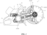
- a power cutting machine 1 includes a main body 2, an arm 3, and a working device 4.
- the main body 2 includes a motor 10 such as an engine and an electric motor.
- the base end of the arm 3 is connected to the main body 2, and the head end of the arm 3 is connected to the working device 4.
- the arm 3 includes a belt transmission mechanism 20 configured to transmit drive power of the motor 10.
- the working device 4 includes a cutting blade 5 connected to the head end of the arm 3 and configured to be rotated by power transmitted via the belt transmission mechanism 20.
- An output shaft of the motor 10 provided in the main body 2 is connected to a drive pulley 21 of the belt transmission mechanism 20 via a well-known clutch mechanism.
- the belt transmission mechanism 20 includes the drive pulley 21, a driven pulley 22 provided in the head end of the arm 3, and an endless belt 23 wound around these pulleys.
- a rotating shaft 5A of the cutting blade 5 is connected to the driven pulley 22 to transmit power of the motor 10 to the cutting blade 5 via the belt transmission mechanism 20.
- the main body 2 includes a rear handle 11 and a front handle 12 as handle parts.
- the rear handle 11 is provided on the rear side of the main body 2, which is close to the operator's body when the operator uses the power cutting machine 1, and an actuating lever 13 of the motor 10 is provided inside the rear handle 11.
- the actuating lever 13 is a throttle lever.
- the front handle 12 is provided on the head side of the main body 2 and extends along the direction orthogonal to the longitudinal direction of the arm 3.
- the working device 4 includes a protecting frame 14.
- the protecting frame 14 is fixed to the head end of the arm 3 and configured to cover the half circle of the cutting blade 5.
- This power cutting machine 1 includes a brake mechanism 30 provided on the arm 3.
- the brake mechanism 30 includes a detection mechanism 31 configured to detect the movement of the arm 3 along with the bounce of the working device 4 and a tightening mechanism 32 configured to be actuated upon detection of the detection mechanism 31 to tighten a tightening belt 32A wound around the drive pulley 21.
- the detection mechanism 31 includes a swing lever 31C configured to pivotally support a mass part 31A around a rotating shaft 31B.
- Fig. 2 is an illustration of an initial state of the detection mechanism 31. In this state, when the working device 4 bounces up, an inertial force F acts on the mass part 31A to swing the swing lever 31C pivotally supported around the rotating shaft 31B in the direction of arrow R.
- the tightening mechanism 32 includes bending members 32B configured to bend along with the swing of the swing lever 31A and pull one end of the tightening belt 32A.
- the bending members 32B are formed in a straight line, and one end of the bending members 32B is supported by a spring 32C.
- a lever part 32F engaged with the swing lever 31C rotates around a rotating shaft 32D; one of the bending members 32B pivotally supported around the rotating shaft 32D is bent.
- the linking part of the bending members 32B bends and releases the spring force caused by the compression of the spring 32C which is a strong compression spring, and therefore the tightening belt 32A is instantly tightened.
- One end of the tightening belt 32A of the tightening mechanism 32 is connected to the bending members 32B, and the other end is fixed to a fixed shaft 32E in the housing of the arm 3.
- the tightening belt 32A naturally tightens the outer circumference of the drive pulley 21 to apply a brake to the drive pulley 21 when the bending members 32B are bent to tighten the tightening belt 32A.
- the detection mechanism 31 detects the movement of the arm 3 when the working device 4 bounces up due to a kickback during cutting work. Then, the brake mechanism 30 is actuated and applies a brake to the drive pulley 21; therefore, the power cutting machine 1 can stop the rotation or reduce the speed of the drive pulley 21 without stopping the motor 10. By this means, the power cutting machine 1 can detect the working device 4 bouncing up due to the kickback via the arm 3 and actuate the brake mechanism 30. Consequently, it is possible to implement an effective measure against the kickback.
- the brake mechanism 30 includes an indicator mechanism 40 configured to allow the braking state to be visually recognized.
- the indicator mechanism 40 By the indicator mechanism 40, a worker can visually recognize the movement of the mass part 31A along with the swing of the swing lever 31C.
- the swing lever 31C is inclined downward when the brake mechanism 30 is in the braking state as illustrated in Fig. 3 , and the mass part 31A movably disposed in the swing lever 31C moves; therefore, the tip of the mass part 31A protrudes from the head end of the swing lever 31C.
- the indicator mechanism 40 can achieve high visibility by using contrasting colors on the outer surface of the swing lever 31C and the mass part 31A protruding from the swing lever 31C.
- the indicator mechanism 40 allows the worker to visually recognize the braking state of the brake mechanism 30 and release it before the restart.
- the swing lever 31C is returned to the state illustrated in Fig. 2 , and therefore the braking state of the brake mechanism 30 is released.
- the mass part 31A is a rod-shaped member incorporated into the swing lever 31C.
- the base end of the mass part 31A contacts a cam face 33 provided in the arm 3.
- the base end of the mass part 31A is located on a cum recess of the cam face 33.
- the base end of the mass part 31A moves to a cam protrusion of the cam face 33; therefore, the head end of the mass part 31A protrudes from the head end of the swing lever 31C.
- the brake mechanism 30 includes the indicator mechanism 40 configured to allow the braking state to be visually recognized; therefore, a worker can visually recognize the braking state of the brake mechanism 30 and avoid operating the actuating lever 13 of the motor 10 when the brake mechanism 30 is in the braking state.
Landscapes
- Engineering & Computer Science (AREA)
- Mechanical Engineering (AREA)
- Life Sciences & Earth Sciences (AREA)
- Wood Science & Technology (AREA)
- Forests & Forestry (AREA)
- Sawing (AREA)
- Knives (AREA)
- Processing Of Stones Or Stones Resemblance Materials (AREA)
- Auxiliary Devices For Machine Tools (AREA)
Applications Claiming Priority (1)
| Application Number | Priority Date | Filing Date | Title |
|---|---|---|---|
| JP2023077174A JP2024162028A (ja) | 2023-05-09 | 2023-05-09 | 動力切断機 |
Publications (1)
| Publication Number | Publication Date |
|---|---|
| EP4461448A1 true EP4461448A1 (fr) | 2024-11-13 |
Family
ID=91030085
Family Applications (1)
| Application Number | Title | Priority Date | Filing Date |
|---|---|---|---|
| EP24174580.1A Pending EP4461448A1 (fr) | 2023-05-09 | 2024-05-07 | Machine de coupe électrique |
Country Status (3)
| Country | Link |
|---|---|
| US (1) | US20240375196A1 (fr) |
| EP (1) | EP4461448A1 (fr) |
| JP (1) | JP2024162028A (fr) |
Citations (6)
| Publication number | Priority date | Publication date | Assignee | Title |
|---|---|---|---|---|
| JP2011251348A (ja) | 2010-05-31 | 2011-12-15 | Hitachi Koki Co Ltd | エンジンカッター |
| US20150260241A1 (en) * | 2012-10-03 | 2015-09-17 | Hilti Aktiengesellschaft | Hand-Operated Tool Device With A Brake Mechanism For Braking A Machining Tool |
| DE102014007878A1 (de) * | 2014-05-24 | 2015-11-26 | Andreas Stihl Ag & Co. Kg | Handgeführtes Arbeitsgerät |
| DE102017005558A1 (de) * | 2017-06-09 | 2018-12-13 | Andreas Stihl Ag & Co. Kg | Verfahren zur Ermittlung des Verschleißzustandes einer Bremseinrichtung in einem handgeführten Arbeitsgerät |
| US10816048B2 (en) * | 2017-06-09 | 2020-10-27 | Andreas Stihl Ag & Co. Kg | Work apparatus having an electromagnetic brake assembly |
| EP3412392B1 (fr) * | 2017-06-09 | 2021-09-01 | Andreas Stihl AG & Co. KG | Appareil de travail manuel comprenant un outil et un dispositif de frein pour l'outil |
Family Cites Families (9)
| Publication number | Priority date | Publication date | Assignee | Title |
|---|---|---|---|---|
| US1450906A (en) * | 1919-07-28 | 1923-04-10 | Charles W Anderson | Power control for saw tables and the like |
| US3581481A (en) * | 1969-05-26 | 1971-06-01 | Yard Man Inc | Rotary mower blade brake |
| JPS52157588U (fr) * | 1976-05-25 | 1977-11-30 | ||
| DE3639650A1 (de) * | 1986-11-20 | 1988-06-01 | Stihl Maschf Andreas | Motorkettensaege |
| US20150273725A1 (en) * | 1999-10-01 | 2015-10-01 | Sd3, Llc | Table saws with detection and reaction systems |
| US8006596B2 (en) * | 2005-03-11 | 2011-08-30 | Walter Meier (Manufacturing) Inc. | Cutting tool and parts and accessories therefor |
| WO2008103079A1 (fr) * | 2007-02-22 | 2008-08-28 | Husqvarna Aktiebolag | Dispositif de retardement pour machine coupante rotative |
| EP2969334B1 (fr) * | 2013-03-14 | 2018-05-16 | Robert Bosch GmbH | Système de freinage automatique pour un outil motorisé pivotant et procédé associé |
| US11685034B2 (en) * | 2014-05-24 | 2023-06-27 | Andreas Stihl Ag & Co. Kg | Handheld work apparatus |
-
2023
- 2023-05-09 JP JP2023077174A patent/JP2024162028A/ja active Pending
-
2024
- 2024-05-07 US US18/656,753 patent/US20240375196A1/en active Pending
- 2024-05-07 EP EP24174580.1A patent/EP4461448A1/fr active Pending
Patent Citations (6)
| Publication number | Priority date | Publication date | Assignee | Title |
|---|---|---|---|---|
| JP2011251348A (ja) | 2010-05-31 | 2011-12-15 | Hitachi Koki Co Ltd | エンジンカッター |
| US20150260241A1 (en) * | 2012-10-03 | 2015-09-17 | Hilti Aktiengesellschaft | Hand-Operated Tool Device With A Brake Mechanism For Braking A Machining Tool |
| DE102014007878A1 (de) * | 2014-05-24 | 2015-11-26 | Andreas Stihl Ag & Co. Kg | Handgeführtes Arbeitsgerät |
| DE102017005558A1 (de) * | 2017-06-09 | 2018-12-13 | Andreas Stihl Ag & Co. Kg | Verfahren zur Ermittlung des Verschleißzustandes einer Bremseinrichtung in einem handgeführten Arbeitsgerät |
| US10816048B2 (en) * | 2017-06-09 | 2020-10-27 | Andreas Stihl Ag & Co. Kg | Work apparatus having an electromagnetic brake assembly |
| EP3412392B1 (fr) * | 2017-06-09 | 2021-09-01 | Andreas Stihl AG & Co. KG | Appareil de travail manuel comprenant un outil et un dispositif de frein pour l'outil |
Also Published As
| Publication number | Publication date |
|---|---|
| US20240375196A1 (en) | 2024-11-14 |
| JP2024162028A (ja) | 2024-11-21 |
Similar Documents
| Publication | Publication Date | Title |
|---|---|---|
| US4753012A (en) | Chain saw having a braking arrangement | |
| EP0018603B1 (fr) | Commande anti-recul pour un outil à moteur | |
| AU2009286589B2 (en) | Safety device for portable tools with a heat engine, capable of stopping the operation thereof after sudden, violent movements | |
| US4977708A (en) | Portable handheld tool machine having a tensioning device for a belt drive | |
| US10821627B2 (en) | Work apparatus and method for operating the same | |
| US4782593A (en) | Chain saw with a stopping device | |
| US9044875B2 (en) | Chain saw | |
| SE445542B (sv) | Verktyg for atdragning och slutning av en slinga av termoplastband som omger ett foremal | |
| JPH0219214Y2 (fr) | ||
| US20150258703A1 (en) | Hand-Held Tool Apparatus with a Braking Device for Braking of a Machining Tool | |
| US5042626A (en) | Arrangement for actuating a braking device for bringing a motor-driven work tool of a work apparatus to standstill | |
| US3982616A (en) | Latch operated centrifugally released safety clutch for saws | |
| EP4461448A1 (fr) | Machine de coupe électrique | |
| US20150258658A1 (en) | Hand-Held Tool Apparatus with a Braking Device for Braking a Machining Tool | |
| JPS5812706A (ja) | ポ−タブル動力工具 | |
| US4239096A (en) | Power tool safety clutch | |
| EP4461447B1 (fr) | Machine de coupe électrique | |
| US4474269A (en) | Braking device for a power chain saw | |
| EP2969426B1 (fr) | Scie à chaîne avec un mécanisme de frein d'entraînement débrayé/de frein de chaîne | |
| EP0072610A2 (fr) | Mécanisme intégral de freinage et de débrayage | |
| US20150260241A1 (en) | Hand-Operated Tool Device With A Brake Mechanism For Braking A Machining Tool | |
| JP2008271830A (ja) | 電動刈払機 | |
| US4077125A (en) | Automatic safety brake for chain saw | |
| US4480205A (en) | Automatic brake control for rotary electric tools | |
| EP1468796A1 (fr) | Scie à chaíne avec mécanisme de frein et embrayage |
Legal Events
| Date | Code | Title | Description |
|---|---|---|---|
| PUAI | Public reference made under article 153(3) epc to a published international application that has entered the european phase |
Free format text: ORIGINAL CODE: 0009012 |
|
| STAA | Information on the status of an ep patent application or granted ep patent |
Free format text: STATUS: THE APPLICATION HAS BEEN PUBLISHED |
|
| AK | Designated contracting states |
Kind code of ref document: A1 Designated state(s): AL AT BE BG CH CY CZ DE DK EE ES FI FR GB GR HR HU IE IS IT LI LT LU LV MC ME MK MT NL NO PL PT RO RS SE SI SK SM TR |
|
| STAA | Information on the status of an ep patent application or granted ep patent |
Free format text: STATUS: REQUEST FOR EXAMINATION WAS MADE |
|
| 17P | Request for examination filed |
Effective date: 20250507 |