EP4461875A2 - Système de stockage de bâtiments - Google Patents
Système de stockage de bâtiments Download PDFInfo
- Publication number
- EP4461875A2 EP4461875A2 EP24202340.6A EP24202340A EP4461875A2 EP 4461875 A2 EP4461875 A2 EP 4461875A2 EP 24202340 A EP24202340 A EP 24202340A EP 4461875 A2 EP4461875 A2 EP 4461875A2
- Authority
- EP
- European Patent Office
- Prior art keywords
- sliding
- bearing
- structural
- support system
- building support
- Prior art date
- Legal status (The legal status is an assumption and is not a legal conclusion. Google has not performed a legal analysis and makes no representation as to the accuracy of the status listed.)
- Pending
Links
Images




Classifications
-
- E—FIXED CONSTRUCTIONS
- E01—CONSTRUCTION OF ROADS, RAILWAYS, OR BRIDGES
- E01D—CONSTRUCTION OF BRIDGES, ELEVATED ROADWAYS OR VIADUCTS; ASSEMBLY OF BRIDGES
- E01D19/00—Structural or constructional details of bridges
- E01D19/04—Bearings; Hinges
-
- E—FIXED CONSTRUCTIONS
- E01—CONSTRUCTION OF ROADS, RAILWAYS, OR BRIDGES
- E01D—CONSTRUCTION OF BRIDGES, ELEVATED ROADWAYS OR VIADUCTS; ASSEMBLY OF BRIDGES
- E01D19/00—Structural or constructional details of bridges
- E01D19/04—Bearings; Hinges
- E01D19/042—Mechanical bearings
- E01D19/047—Pot bearings
-
- E—FIXED CONSTRUCTIONS
- E04—BUILDING
- E04B—GENERAL BUILDING CONSTRUCTIONS; WALLS, e.g. PARTITIONS; ROOFS; FLOORS; CEILINGS; INSULATION OR OTHER PROTECTION OF BUILDINGS
- E04B1/00—Constructions in general; Structures which are not restricted either to walls, e.g. partitions, or floors or ceilings or roofs
- E04B1/36—Bearings or like supports allowing movement
-
- E—FIXED CONSTRUCTIONS
- E01—CONSTRUCTION OF ROADS, RAILWAYS, OR BRIDGES
- E01D—CONSTRUCTION OF BRIDGES, ELEVATED ROADWAYS OR VIADUCTS; ASSEMBLY OF BRIDGES
- E01D19/00—Structural or constructional details of bridges
- E01D19/04—Bearings; Hinges
- E01D19/041—Elastomeric bearings
-
- E—FIXED CONSTRUCTIONS
- E01—CONSTRUCTION OF ROADS, RAILWAYS, OR BRIDGES
- E01D—CONSTRUCTION OF BRIDGES, ELEVATED ROADWAYS OR VIADUCTS; ASSEMBLY OF BRIDGES
- E01D19/00—Structural or constructional details of bridges
- E01D19/04—Bearings; Hinges
- E01D19/042—Mechanical bearings
Definitions
- the present invention relates to a building support system with at least two sliding tilting bearings for connecting at least two building parts.
- Structural sliding bearings usually have a lower bearing part that can be connected to the first structural part, a sliding plate that can be connected to a second structural part, and an intermediate bearing part that is arranged between the lower bearing part and the sliding plate.
- the main sliding surface of the structural bearing is usually arranged between the intermediate bearing part and the sliding plate, along which the sliding plate can slide when the structural sliding bearing is in use.
- Structural bearings generally transfer vertical and horizontal loads and enable twisting and relative displacement where necessary.
- Structural sliding bearings are therefore a special type of structural bearing that is generally used for the defined and, if possible, stress-free support of any type of structure, such as bridges, particularly in road and rail traffic, beams and buildings of any kind or parts thereof. They therefore enable relative movements between two structural parts of the structure in question, which can arise, for example, through the use of the structure or through any external influences such as wind or an earthquake.
- damage to the corresponding structures can be avoided in particular.
- Structural bearings can be designed either as bearings that are fixed on all sides or that can be moved on all sides or one side.
- a guided bearing is converted into a fixed bearing by means of locking mechanisms.
- the present invention relates in particular to structural sliding bearings that are guided on one axis or can be moved on one side, which thus enable a sliding movement of the sliding plate along a certain axis direction of the main sliding surface.
- the fixed bearings that are subsequently converted are also relevant for the present invention.
- Structural sliding bearings that are guided on one axis can, for example, They can be implemented as pot bearings or spherical bearings. Both types of structural sliding bearings are shown schematically in the Fig. 1 and 2 and are briefly explained below.
- Fig. 1 shows a uniaxially guided structural sliding bearing in the form of a pot bearing 10, also called a pot sliding bearing, as is known from the prior art.
- the pot sliding bearing 10 has a pot 12 as the lower bearing part, which can be connected to a first part of the structure.
- the pot 12 contains a machined recess 14 for receiving an elastomer cushion 16, an inner seal 18 and a pot cover 20, which represents the intermediate bearing part of the pot sliding bearing 10.
- the pot cover 20 closes the opening of the pot 12 and lies flush on the elastomer cushion 16 arranged underneath.
- the sliding plate 22, which can be connected to a second structural part, is arranged above the pot cover 20.
- Both the pot lid 20 and the sliding plate 22 are aligned horizontally, so that a horizontal main sliding surface 24 of the pot sliding bearing 10 extends between these two components.
- a sliding material 26 is arranged on the pot lid 20 in order to reduce the friction between the pot lid 20 and the sliding plate 22. This enables the sliding plate 22 to slide along the main sliding surface 24 with as little resistance as possible.
- the pot sliding bearing 10 can thus absorb vertically acting forces or loads via the sliding plate 22, the horizontal main sliding surface 24, the pot lid 20 and the elastomer cushion 16 and transfer them to the pot 12 underneath.
- the elastomer cushion 16 enables any twisting of the pot sliding bearing 10. This happens through the elastomer cushion 16 giving way at certain points in the area of the force applied by the pot lid 20.
- the inner seal 18 is arranged in such a way that the elastomer cushion 16 can be prevented from being pressed out through the gap between the pot wall and the pot lid 20 as soon as a pressure load is applied to the elastomer cushion 16.
- an outer seal can be arranged between the pot lid 20 and the pot 12, which keeps moisture and dirt away from the corresponding gap.
- the pot sliding bearing 10 has a central guide rail 28 in order to realize the uniaxial displacement of the sliding plate 22.
- the central guide rail 28 is arranged above the pot lid 20 in the area of the main sliding surface 24 and engages with a corresponding groove in the sliding plate 22.
- the guide rail 28 thus defines the axis of movement of the pot sliding bearing 10 in that it can absorb all horizontal forces transverse to the sliding direction.
- the two sliding surfaces between the guide rail 28 and the sliding plate 22 are arranged vertically along the axis of movement. Horizontally acting forces thus hit the central guide rail 28 perpendicularly from both sides and can thus be absorbed effectively.
- the guide rail 28 also has a sliding material 30 along both vertical sliding surfaces, which is initially lubricated. The friction between the guide rail 28 and the sliding plate 22 is thus reduced and movement of the sliding plate 22 along the axis of movement is made easier.
- a uniaxially guided structural sliding bearing is shown in the form of a spherical bearing 110, as is known from the prior art.
- the spherical bearing 110 has a bearing base 112 that can be connected to a first part of the structure.
- the spherical bearing 110 also includes a spherical cap 114 that represents the intermediate bearing part of the spherical bearing 110.
- the spherical cap 114 is curved convexly downwards and is received in a correspondingly concave section on the top of the bearing base 112.
- a secondary sliding surface 116 or secondary sliding surface of the spherical bearing 110 is thus formed between the spherical cap 114 and the bearing base 112.
- a sliding material 118 is arranged in the area of the secondary sliding surface 116 in order to enable the spherical cap 114 to move with as little resistance as possible within the concave section of the bearing base 112.
- the sliding plate 120 rests above the spherical cap and can be connected to a second part of the structure.
- the horizontal main sliding surface 122 or primary sliding surface of the spherical bearing 110 is thus located between the spherical cap 114 and the sliding plate 120.
- a sliding material 124 is arranged on the spherical cap 114 in the area of the main sliding surface 122 in order to reduce the friction between the spherical cap 114 and the sliding plate 120. This also enables the sliding plate 24 to slide along the main sliding surface 122 with as little resistance as possible.
- the spherical bearing 114 can thus absorb vertically acting forces or loads via the sliding plate 120, the horizontal main sliding surface 122 and the spherical cap 114 and transfer them to the bearing base 112. At the same time, the convex curvature of the spherical cap 144 and the receiving concave section of the bearing base 112 enable corresponding rotations of the spherical cap 114 or the spherical bearing 110. This happens here by the spherical cap 114 sliding along the secondary sliding surface 116.
- the single-axis guidance of the spherical bearing 114 is achieved by two horizontal lateral guide rails 126. These are each arranged next to the main sliding surface 122 on the side of the bearing base 112 in order to engage with the sliding plate 120. In this case, too, any horizontal forces transverse to the two lateral guide rails 126 are absorbed, thereby defining the axis of movement of the spherical bearing 110. As with the pot sliding bearing 10, the sliding surfaces between the two lateral guide rails 126 and the sliding plate 120 are each formed vertically along the axis of movement. Due to the vertical action of the horizontal forces on the sliding surfaces of the two guide rails 126, even higher forces can be effectively absorbed.
- the two lateral guide rails 126 also have a sliding material 128 in the area of the vertical sliding surfaces, which is initially lubricated.
- the friction between the two guide rails 126 and the sliding plate 120 can thus be significantly reduced, which simplifies the movement of the sliding plate 120 along the movement axis accordingly.
- the serviceability condition extends up to and including the serviceability limit state. If this limit is exceeded, the specified conditions for the serviceability of a structure are or a component are no longer met.
- Limit states that affect the function of the structure or one of its parts under normal conditions of use or the well-being of the users or the appearance of the structure are also to be classified as serviceability limit states.
- the service condition may still exist when the extreme case occurs. This applies in particular to the condition after any emergency and buffer functions have been triggered, which are only used in extreme cases.
- a targeted lifting of the sliding plate from the intermediate bearing part is provided during the service condition.
- orientation information relates only to the plane of movement of the structural sliding bearing or the structural bearing system. This applies in particular if the structural sliding bearing or the structural bearing system is installed at an angle, for example. In this case, the orientation of the horizontal main sliding surface can differ from a horizontal plane in the narrower sense and can be set at an angle accordingly. The same applies to the vertical guide surfaces arranged perpendicular to them and the correspondingly described force effects.
- single-axis guided structural sliding bearings with a central guide rail are of limited use when absorbing very high forces.
- the rotation of the bearing around the vertical axis is hindered.
- the structural sliding bearings described represent complex structures that require a correspondingly high level of effort in terms of installation space and the costs for production and maintenance. The same disadvantages apply to structural bearing systems that have such structural sliding bearings.
- the structural bearing system comprises at least two sliding bearings for connecting at least two structural parts.
- Each sliding bearing has a lower bearing part that can be connected to a first structural part, a sliding plate that can be connected to a second structural part, and an intermediate bearing part that is arranged between the lower bearing part and the sliding plate.
- At least one flat main sliding surface of the sliding bearing is arranged between the intermediate bearing part and the sliding plate.
- the structural bearing system is further characterized in that the two sliding bearings form a bearing pair in which the main sliding surface of the first sliding bearing is arranged in a first sliding plane angled to the horizontal and the main sliding surface of the second sliding bearing is arranged in a second sliding plane angled to the horizontal.
- the sliding planes meet in a common intersection line that forms a movement axis of the bearing pair along which the sliding plates can move.
- the two main sliding surfaces of the first sliding bearing and the second sliding bearing which are inclined towards each other, achieve a functional combination of vertical and horizontal force transfer within the bearing pair and thus also of the entire structural bearing system.
- the first sliding bearing can absorb horizontal forces from only one specific direction transversely to the axis of movement can absorb, the horizontal forces from the opposite direction are absorbed by the second sliding bearing. Both sliding bearings thus complement each other to form a structural bearing system.
- the two inclined main sliding surfaces enable the system of the two sliding plates and the connected structure to continuously self-center relative to the axis of movement defined by the two sliding bearings.
- This system is therefore always optimally positioned relative to the intermediate bearing parts of the two sliding bearings and possible edge pressures along the axis of movement can be avoided.
- This type of arrangement is therefore particularly advantageous when building bridges for high-speed train routes. In this case, it is essential to avoid a corresponding lateral offset.
- the two separate sliding plates of the two sliding bearings also provide for easy height adjustment. In particular, it is possible to adjust the distance between the two sliding plates and the respective bearing bases. The distance between the two structural parts is therefore also changed accordingly. If the two sliding plates are synchronously pushed towards or apart from one another along the corresponding sliding planes across the axis of movement, the horizontal distance between the two sliding plates and the respective bearing bases of the two sliding bearings also changes. However, if, for example, only one of the two sliding plates is moved in this way or if both sliding plates are moved non-synchronously, the position of the second structural part is tilted relative to the first structural part. Alternatively, the two sliding plates can also be formed as one piece.
- the horizontal is to be understood in relation to the movement plane of the building support system.
- the horizontal can therefore also have a different orientation than a horizontal plane in the narrower sense.
- the at least two plain bearings are designed as sliding tilting bearings.
- spherical bearings would be conceivable, which have the advantages described above.
- the at least two plain bearings can be designed as elastomer bearings. In addition to their sliding properties, these also have deformation properties in the intermediate part of the bearing, which means that twisting and point loads can be compensated particularly effectively.
- the first sliding plane and the second sliding plane expediently enclose a first angle, with the first angle being selected such that no gaping joint occurs in the area of the main sliding surfaces when the building support system is in use.
- the ratio between the maximum possible vertical force and horizontal force of the building support system that can be absorbed can be adjusted by the inclination of the two main sliding surfaces to one another or the selection of the first angle. This can be done without having to adjust the dimensions of the individual main sliding surfaces. By selecting the appropriate inclination of the two main sliding surfaces to one another, a gaping joint in the area of the main sliding surfaces can be avoided when the building support system is in use, even with maximum horizontal force in combination with the corresponding minimum vertical force.
- the two inclined main sliding surfaces are designed to be so steep against the respective horizontal force that a gaping joint or lifting of the sliding plates from the respective intermediate bearing parts does not occur when the structural bearing system is in use.
- a sliding material with the lowest possible friction can be used in the area of the main sliding surfaces in order to facilitate the movement of the sliding plates in the direction of the movement axis as much as possible.
- the bearing pair is a uniaxially guided bearing pair in which the sliding plates can only move along the axis of movement relative to the intermediate bearing parts. This ensures that the structural bearing system does not allow any further movements of the sliding plates other than along the axis of movement relative to the intermediate bearing parts.
- the structural bearing system can therefore be used specifically when horizontal movements in a single direction are to be permitted.
- first sliding plane and the second sliding plane are arranged so that the line of intersection is horizontal.
- the movement axis of the bearing pair is also horizontal.
- the bearing pair is evenly loaded in terms of force transfer.
- the sliding plates can move evenly with identical resistance in both directions of the As explained above, the horizontal alignment is to be understood in relation to the plane of movement of the structural support system.
- the cutting line can therefore also have a different alignment than a horizontal line in the narrower sense.
- the first angle is advantageously selected in such a way that in the ultimate limit state of the structural bearing system, no gaping joint is created in the area of the main sliding surfaces. If the loads on the structural bearing system are increased further from the serviceable state, the ultimate limit state occurs. According to the DIN EN 1990:2010-12 standard for fundamentals of structural design, this state is associated with collapse or other forms of structural failure.
- the limit states that affect the safety of people and/or the safety of the structure are therefore also to be classified as ultimate limit states. This ensures that even in this state, no gaping joint is created in the area of the main sliding surfaces and that the sliding plate does not lift off the intermediate bearing part.
- At least one main sliding surface expediently has a permanently lubricated sliding material, preferably with PTFE, UHMWPE, POM and/or PA.
- the permanently lubricated sliding material in the area of the main sliding surface can significantly reduce the friction between the sliding plate and the intermediate bearing part. Due to the inclined main sliding surfaces, a sliding material with a low coefficient of friction can be used here. High horizontal forces can be absorbed by a corresponding inclination of the main sliding surfaces. This makes it easier for the sliding plate to slide along the axis of movement.
- the sliding material preferably has a coefficient of friction that is a maximum of 0.03 for the design value of the pressure in the sliding material.
- the sliding material preferably has at least one lubricated sliding disk, which preferably has at least one lubrication pocket.
- the prefabricated lubrication pockets can store the lubricant and distribute it evenly over the sliding surface. This creates a particularly low-wear sliding material with a low coefficient of friction. This facilitates the sliding movement of the corresponding sliding plate along the movement axis and extends the maintenance intervals of the structural bearing system.
- At least two main sliding surfaces are arranged at an angle to one another in such a way that the corresponding sliding planes form the shape of a gable roof.
- the gable roof is designed in such a way that the cutting line or the axis of movement forms the ridge of the gable roof.
- the shape of a gable roof has the particular advantage that any accumulation of dirt and foreign bodies in the area of the main sliding surfaces can be largely avoided. This applies in particular in the area of the axis of movement if the first and second sliding bearings are installed in close proximity, since the axis of movement as the ridge represents the highest point of the gable roof.
- At least two main sliding surfaces are arranged at an angle to one another in such a way that the corresponding sliding planes form the shape of an upside-down gable roof.
- the gable roof is designed in such a way that the cutting line or the axis of movement forms the ridge of the gable roof. Due to the upside-down roof shape, it is possible to make the respective sliding plate stronger at the end towards the axis of movement without requiring additional installation space in the vertical direction. This means that installation space can be saved again despite increased loads.
- At least two main sliding surfaces that are angled to one another are expediently designed symmetrically to one another with respect to a plane of symmetry that runs through the cutting line in the vertical direction.
- the arrangement according to the invention enables improved self-centering of the system comprising the two sliding plates and the connected structure relative to the axis of movement defined by the two sliding bearings.
- the structure support system is simple in design and is therefore cost-effective to manufacture.
- the vertical direction is to be understood with reference to the plane of movement of the structure support system.
- the vertical direction can also have a different orientation than a vertical in the narrower sense.
- At least two main sliding surfaces that are angled to one another are of different sizes.
- This design is particularly advantageous when horizontal forces of different magnitudes act on the structural support system from different directions.
- the structural support system according to the invention can thus be specially designed to be able to absorb larger forces acting from a certain horizontal direction transverse to the axis of movement than from an opposite direction. This can prevent a gaping joint from forming or the sliding plate from lifting off, even if the force is uneven.
- At least one sliding plane is expediently inclined downwards from the horizontal by a second angle of between 0 degrees and 10 degrees, preferably by 6 degrees.
- a second angle of between 0 degrees and 10 degrees, preferably by 6 degrees.
- the respective inclined main sliding surfaces can absorb correspondingly higher horizontal forces transverse to the axis of movement.
- it ensures that the sliding plate moves along the axis of movement with as little resistance as possible.
- the horizontal is to be understood with reference to the plane of movement of the building bearing system.
- the horizontal can also have a different orientation than a horizontal plane in the narrower sense.
- the second angle corresponds at least to the permissible friction to be assumed for the design.
- the first angle is preferably between 160 degrees and 180 degrees, preferably 168 degrees.
- the respective inclined main sliding surfaces can absorb correspondingly higher horizontal forces across the axis of movement.
- the first sliding bearing and/or the second sliding bearing has a stop device, preferably on the side, which limits movement of the sliding plate relative to the lower part of the bearing. A twisting of the second structural part relative to the first structural part is thus counteracted.
- the stop device is preferably designed such that a moment acting on the second structural part is supported about an axis parallel to the axis of movement.
- the stop device can be designed, for example, as a one-piece stop or also in several parts. In one example, the stop device is attached to the lower part of the bearing.
- the stop device is advantageously arranged on a side of the respective plain bearing that faces or is inclined away from the axis of movement. This arrangement makes it possible to specifically absorb moments that act on the second structural part about an axis parallel to the axis of movement.
- the stop device is preferably arranged on the side of the plain bearing that is higher in the vertical direction. This has the advantage that, for small or negligible moments, it is mainly the vertical force component of the dead weight that acts on the bearing in relation to the operational load.
- the stop device is completely force-free. This significantly reduces wear on the stop device and increases its service life.
- the stop device expediently has an adjustment device to adjust a position of the stop device.
- the adjustment device can be used to optimally and precisely adjust the stop device to the individual components of the plain bearing depending on the situation.
- the adjustment device can be implemented using a screw connection, for example. It is also conceivable that the adjustment device has an electric motor to adjust the position of the stop device particularly precisely and/or automatically.
- the stop device has a sliding device that guides the sliding plate in a direction parallel to the axis of movement. Due to the sliding device, the stop device enables movement towards or away from the Movement axis a movement of the sliding plate relative to the bearing base along the movement axis with as little friction as possible.
- the sliding device is designed as a sliding strip.
- the structural bearing system advantageously has at least two bearing pairs and an axis.
- the bearing pairs are arranged one after the other along the axis, with the main sliding surfaces angled to one another being arranged in such a way that the corresponding sliding planes of the bearing pairs alternately form the shape of a gable roof and the shape of an upside-down gable roof along the axis.
- the axis can preferably be designed to be straight.
- a curved axis would also be conceivable, as can be the case with a roadway, a track section or a pipeline, for example.
- the alternating arrangement of the main equal surfaces allows possible torsional moments of the structure to be absorbed in a targeted manner.
- the structural support system preferably has at least two pairs of bearings and an axis.
- the pairs of bearings are arranged one after the other along the axis, with the main sliding surfaces angled to one another being arranged in such a way that the corresponding sliding planes of the pairs of bearings alternately form the shape of a gable roof and the shape of an upside-down gable roof for every second pair of bearings along the axis.
- the axis can preferably be designed to be straight.
- a curved axis would also be conceivable, as can be the case with a roadway, a track section or a pipeline, for example. This principle can be used in particular when several single-span beams are supported one behind the other along the axis by the structural support system.
- each single-span beam is held by a pair of bearings.
- a consistent arrangement of the main sliding surfaces of both pairs of bearings is used at the connection points between the single-span beams.
- a height offset in the joint between the two single-span beams can be kept as small as possible.
- the inclination of the main sliding surfaces of two consecutive plain bearings along the axis in the area of such a connection point is also identical. This can further reduce the risk of a height offset.
- the structural support system according to the invention is thus constructed as simply as possible and can simultaneously operate maintenance-free and reliably for a long time under increased force. The costs and effort involved in the manufacture and operation of the structural support system are thus reduced.
- the structural sliding bearing 210 is designed in the form of a uniaxially guided spherical bearing and has a bearing base 212 for force transfer, which can be connected to a first structural part, a spherical bearing intermediate part 214 and a sliding plate 216, which can be connected to a second structural part.
- the bearing base 212 has a concave section 218 in which the spherical cap is slidably received with its convex section 220.
- the secondary sliding surface 222 of the structural sliding bearing 210 is thus located between the convex section 220 of the spherical cap and the concave section 218 of the bearing base 212.
- a sliding material 224 in the form of a polymer sliding disk is arranged on the concave section 218 of the bearing base 212. This allows the friction between the convex section 220 of the spherical cap and the concave section 218 of the bearing base 212 to be reduced. The movement of the spherical cap relative to the bearing base 212 is thus facilitated and the structural sliding bearing 210 enables rotation about the vertical and horizontal axis.
- the sliding plate 216 rests slidably on the calotte in order to be connected above with the second structural part.
- the main sliding surface 226 of the structural sliding bearing 210 is arranged between the calotte and the sliding plate 216.
- the main sliding surface 226 has two partial sliding surfaces 228A and 228B inclined towards one another. Both partial sliding surfaces 228A and 228B are arranged in two sliding planes 230A and 230B angled towards one another, which meet in a common horizontal intersection line S.
- the intersection line S forms the movement axis A of the structural sliding bearing 210, along which the sliding plate 216 can move. In this way, corresponding displacements of the first structural part relative to the second structural part can be permitted.
- the two partial sliding surfaces 228A and 228B inclined towards one another are arranged in such a way that the corresponding sliding planes 230A and 230B form the shape of a gable roof.
- the shape of an upside-down gable roof would also be conceivable here, with the movement axis A forming the ridge of the gable roof.
- the two partial sliding surfaces 228A and 228B inclined towards one another are of the same size and related to a line formed by the intersection line S in vertically extending symmetry plane E are formed symmetrically to each other.
- the two partial sliding surfaces 228A and 228B inclined towards each other could also be formed with different sizes (not shown).
- the main sliding surface 226 has a sliding material 232 to reduce the friction between the cap and the sliding plate 216.
- each of the two partial sliding surfaces 228A and 228B inclined towards one another has a permanently lubricated polymer sliding disk, each of which is mounted in a recess 234 on the cap.
- the polymer sliding disk is made of PTFE, UHMWPE, POM and/or PA and has prefabricated lubrication pockets in which the lubricant can be stored and evenly released over the entire contact surface.
- the sliding material 232 has a very low coefficient of friction and is particularly low-wear in use. In the present embodiment, the coefficient of friction is a maximum of 0.03.
- the special arrangement of the main sliding surface 226 or the two partial sliding surfaces 228A and 228B inclined towards one another enables a functional combination of vertical and horizontal force transfer.
- the structural sliding bearing 210 can absorb vertically acting forces via the two partial sliding surfaces 228A and 228B inclined towards one another and transfer them from the second structural part to the first structural part.
- vertically acting forces are thus introduced from the second structural part to the first structural part via the sliding plate 216, the calotte and the bearing base 212.
- horizontal forces directed transversely to the movement axis A can also be absorbed by the two partial sliding surfaces 228A and 228B inclined towards one another and transferred accordingly between the two structural parts.
- both sliding planes 230A and 230B enclose a first angle ⁇ , which is selected such that in the state of use of the structural sliding bearing 210, no gaping joint occurs in the area of the main sliding surface 226.
- the first angle ⁇ of the structural sliding bearing 210 is even selected such that even in the limit state of the structural sliding bearing 210, no gaping joint occurs in the area of the main sliding surface 226.
- the Fig. 3 to 7 The structural sliding bearing 210 shown has a first angle of 168 degrees. However, if the structural sliding bearing 210 is to be designed for very high horizontal forces, a more acute first angle ⁇ can also be used.
- both sliding planes 230A and 230B are inclined downwards with respect to the horizontal H by a second angle ⁇ .
- both sliding planes 230A and 230B of the structural sliding bearing 210 have the same second angle ⁇ , which is 6 degrees.
- ⁇ is 6 degrees.
- a particularly steep angle can also be selected. It would also be possible for the sliding plane 230A to have a different second angle ⁇ than the sliding plane 230B in order to specifically absorb different levels of force from different directions (not shown).
- FIG. 8 a sequence of two schematic cross-sectional representations of a structural sliding bearing 310 is shown according to an example, which illustrates a height adjustment of the structural sliding bearing.
- the structural sliding bearing 310 essentially corresponds to the structural sliding bearing 210.
- the identical components will not be discussed further below.
- the structural sliding bearing 310 differs from the structural sliding bearing 210 in that the sliding plate 316 is made up of several parts and the distance between the corresponding sliding plate parts 316A and 316B is adjustable.
- the sliding plate 316 is simply divided into two halves, so that the sliding plate 316 is formed by two identically sized sliding plate parts 316A and 316B.
- the two sliding plate parts 316A and 316B are each arranged along one of the two partial sliding surfaces 228A and 228B inclined towards one another in order to enable a horizontal connection of the second structural part.
- the first total height G1 of the structural sliding bearing is changed by a height difference ⁇ H.
- a height difference ⁇ H This enables a simple height adjustment of the structural sliding bearing 310.
- a final state of the structural sliding bearing 310 is shown after the two sliding plate parts 316A and 316B have been pushed towards each other. As can be seen from the illustration, the horizontal first distance d1 between the two sliding plate parts 316A and 316B has been reduced to the horizontal second distance d2.
- both sliding plate parts 316A and 316B still have the same horizontal distance from the movement axis A.
- the first total height G1 is increased by the height difference ⁇ H to a second total height G2. If, however, the two sliding plate parts 316A and 316B are pushed apart, the first total height G1 is reduced accordingly.
- the Fig. 9 shows a schematic exploded drawing of an exemplary structural sliding bearing 410.
- the structural sliding bearing 410 essentially corresponds to the structural sliding bearing 210.
- the identical components will not be discussed further below.
- the structural sliding bearing 410 differs from the structural sliding bearing 210 in that the concave section 418 of the bearing base 412 has a recess 436 at a lower pole P, so that in the area of the recess 436 the convex section 220 of the cap does not come into contact with the concave section 418 of the bearing base 412.
- this recess 436 is formed in the polymer sliding disk of the sliding material 424 in the area of the secondary sliding surface 422.
- the recess 436 has a circular shape that is centered on the lower pole P.
- the recess 436 at the lower pole P increases the radius of gyration.
- the counteracting pressure from the acting vertical load increases accordingly compared to the pressure from the lifting horizontal force.
- This ratio can be controlled by the diameter D of the recess 436.
- even greater forces can be absorbed by the structural sliding bearing 410.
- the structural sliding bearing 410 with the recess 436 offers a further adjustment option for adjusting the ratio between the vertical forces that can be absorbed and the horizontal forces.
- the choice of the inclination of the two partial sliding surfaces 228A and 228B inclined towards one another can be coordinated with the diameter D of the recess 436 in order to optimally design the structural sliding bearing 410 for a wide variety of force effects.
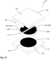
- FIG. 10 a schematic exploded drawing of an exemplary structural sliding bearing 510 is shown.
- the structural sliding bearing 510 essentially corresponds to the structural sliding bearing 210.
- the identical components will not be discussed further below.
- the structural sliding bearing 510 differs from the structural sliding bearing 210 in that the sliding plate 516 has two stops 538.
- the stops 538 are attached to the sliding plate 538 in the middle, on the side and opposite each other. Both stops 538 protrude in the direction of the bearing base 212, so that the stops 538 are arranged between the bearing base 212 and the sliding plate 516. The movement of the sliding plate 516 relative to the bearing base 212 is thus limited.
- the stops 538 are designed such that the structural sliding bearing 510 is converted into a fixed bearing.
- the Fig. 11 shows a perspective view of an exemplary structural sliding bearing 610.
- the structural sliding bearing 610 essentially corresponds to the structural sliding bearing 210.
- the identical components will not be discussed further below.
- the structural sliding bearing 610 differs from the structural sliding bearing 210 in that it is designed as a pot bearing.
- the intermediate bearing part 614 is designed as a pot cover on which the sliding plate 216 rests in a sliding manner.
- the lower bearing part 612 has a pot with an elastomer cushion 640 in order to enable small twists or displacements of the pot cover arranged above it and thus of the pot bearing. All advantages of the main sliding surface discussed apply accordingly.
- a schematic side view of a structural bearing system 700 according to the invention is shown according to a first embodiment.
- the structural bearing system 700 thus has a first sliding bearing 710A and a second sliding bearing 710B in order to connect a first structural part 712 to a second structural part 714.
- the first sliding bearing 710A and the second sliding bearing 710B are each designed as sliding tilting bearings.
- the first sliding tilt bearing 710A and the second sliding tilt bearing 710B basically have identical components.
- the first sliding tilt bearing 710A includes a bearing base 716A that can be connected to the first structural part 712, a sliding plate 718A that can be connected to the second structural part 714, and an intermediate bearing part 720A or a tilting part that is arranged between the bearing base 716A and the sliding plate 718A.
- a flat main sliding surface 722A of the first sliding tilt bearing 710A extends between the intermediate bearing part 720A and the sliding plate 718A.
- the second sliding tilting bearing 710B also has a bearing base 716B that can be connected to the first structural part 712, a sliding plate 718B that can be connected to the second structural part 714, and an intermediate bearing part 720B or a tilting part that is arranged between the bearing base 716B and the sliding plate 718B. Accordingly, a flat main sliding surface 722B of the second sliding tilting bearing 710B also extends between the intermediate bearing part 720B and the sliding plate 718B.
- Both sliding tilt bearings 710A and 710B form a uniaxially guided bearing pair, in which the main sliding surface 722A of the first sliding tilt bearing 710A is arranged in a first sliding plane 724A inclined to the horizontal H.
- the main sliding surface 722B of the second sliding tilt bearing 710B is also arranged in a second sliding plane 724B inclined to the horizontal H.
- Both sliding planes 724A and 724B meet in a common horizontal intersection line S, which thus forms the movement axis A of the bearing pair and along which the two sliding plates 718A and 718B can move. In this way, corresponding displacements of the first structural part 712 relative to the second structural part 714 can be permitted.
- the two inclined main sliding surfaces 722A and 722B are arranged in such a way that the first sliding plane 724A and the second sliding plane 724B form the shape of an upside-down gable roof.
- the shape of a normal gable roof would also be conceivable here, with the movement axis A forming the ridge of the gable roof.
- the two main sliding surfaces 722A and 722B inclined towards one another are the same size and are symmetrical to one another with respect to a plane of symmetry E running through the cutting line S in the vertical direction.
- the two main sliding surfaces 722A and 722B inclined towards one another could also be of different sizes (not shown).
- both main sliding surfaces 722A and 722B each have a sliding material 726 to reduce the friction between the two intermediate bearing parts 720A and 720B and the respective sliding plate 718A and 718B.
- each of the two inclined main sliding surfaces 722A and 722B includes a permanently lubricated polymer sliding disk, which is each mounted in a recess 728 on the respective intermediate bearing part 720A and 720B.
- the polymer sliding disk is made of PTFE, UHMWPE, POM and/or PA and has prefabricated lubrication pockets in which the lubricant can be stored and released evenly over the entire contact surface.
- the sliding material 726 has a very low coefficient of friction and is particularly low-wear in use. In the present embodiment, the coefficient of friction is a maximum of 0.03.
- the special arrangement of the two main sliding surfaces 722A and 722B also enables a functional combination of vertical and horizontal force transfer within the bearing pair.
- the bearing pair can absorb vertically acting forces via the two inclined main sliding surfaces 722A and 722B and transfer them from the second structural part 714 to the first structural part 712.
- vertically acting forces are thus introduced from the second structural part 714 to the first structural part 712 via the two sliding plates 718A and 718B, the two intermediate bearing parts 720A and 720B and the lower bearing parts 716A and 716B.
- the two main sliding surfaces 722A and 722B inclined towards one another can also absorb horizontal forces directed transversely to the movement axis A and transfer them accordingly between the two structural parts 712 and 714.
- both sliding planes 724A and 724B enclose a first angle ⁇ , which is selected such that in the state of use of the structural support system 700 no gaping joint occurs in the area of the two main sliding surfaces 722A and 722B.
- the first angle ⁇ of the structural support system 700 is even selected such that even in the limit state of the load-bearing capacity of the structural support system 700 no gaping joint occurs in the area of the two main sliding surfaces 722A and 722B.
- the illustrated The structural bearing system 700 has a first angle ⁇ of 140 degrees. However, if the structural sliding bearing 700 is to be designed for less high horizontal forces, a more obtuse first angle ⁇ can also be used, for example between 160 degrees and 180 degrees or exactly 168 degrees.
- both sliding planes 724A and 724B are inclined downwards with respect to the horizontal H by a second angle ⁇ .
- both sliding planes 724A and 724B of the building support system 700 have the same second angle ⁇ , which is 20 degrees here.
- a flatter second angle ⁇ can also be selected, for example between 0 degrees and 10 degrees or exactly 6 degrees. It would also be possible for the sliding plane 724A to have a different second angle ⁇ than the sliding plane 724B in order to specifically absorb forces of different magnitudes from different directions (not shown).
- the two sliding tilt bearings 710A and 710B in the structural bearing system 700 each have a separate sliding plate 718A and 718B, a simple height adjustment is also possible here with the help of the corresponding bearing pair.
- the principle of the Fig. 8 shown height adjustment can be used, wherein the two sliding plates 718A and 718B each represent a sliding plate part 316A or 316B of the two-part sliding plate 316.
- FIG. 13 a schematic side view of a building storage system 700 according to the invention according to a second embodiment is shown.
- the building storage system 700 of the second embodiment corresponds essentially to the building storage system 700 of the first embodiment.
- the components with the same structure will not be discussed further below.
- the building support system 700 of the second embodiment differs from the building support system 700 of the first embodiment in that the two inclined main sliding surfaces 722A and 722B are arranged such that the first sliding plane 724A and the second sliding plane 724B form the shape of a normal gable roof.
- the first sliding tilting bearing 710A has a lateral stop device 730A which limits movement of the sliding plate 718A relative to the bearing base 716A.
- the stop device 730A is arranged on a side of the first sliding tilting bearing 710A which faces the movement axis A.
- the stop device 730A is formed in one piece and fastened to the bearing base 716A.
- the stop device 730A has a sliding device 732A in the form of a sliding strip which guides the sliding plate 718A in a direction parallel to the movement axis A.
- a sliding device 732A in the form of a sliding strip which guides the sliding plate 718A in a direction parallel to the movement axis A.
- the second sliding tilt bearing 710B has a lateral stop device 730B, which limits a movement of the sliding plate 718B relative to the bearing base 716B.
- the stop device 730B is arranged on a side of the second sliding tilt bearing 710B that faces the movement axis A.
- the stop device 730B is formed in one piece and fastened to the bearing base 716B.
- the stop device 730B has a sliding device 732B in the form of a sliding strip, which guides the sliding plate 718B in a direction parallel to the movement axis A.
- a moment M acts on the second structural part 714 around an axis parallel to the movement axis A in a clockwise direction, it is pulled against the stop device 730A of the first sliding tilting bearing 710A and is supported on the other side in the instantaneous pole MP in the base of the second sliding tilting bearing 710B.
- a force F acts in the stop device 730A which counteracts the rotation of the second structural part 714.
- the second structural part 714 is pulled against the stop device 730B of the second sliding tilting bearing 710B and is supported on the other side in the instantaneous pole in the base of the first sliding tilting bearing 710A.
- both stop devices 730A and 730B are arranged on the side of the corresponding sliding tilting bearing 710A and 710B that is higher in the vertical direction. If the acting moments are small or negligible, the vertical force component of the dead weight acts primarily on the bearing in relation to the operational load, whereby the stop devices 730A and 730B are completely force-free. Thus, with appropriate dimensioning, the stop devices 730A and 730B are only rarely activated, which is beneficial for the service life due to fatigue.
- the Fig. 14 shows a schematic side view of a building storage system 700 according to the invention in accordance with a third embodiment.
- the building storage system 700 of the third embodiment essentially corresponds to the building storage system 700 of the second embodiment.
- the components with the same structure will not be discussed further below.
- the structural bearing system 700 of the third embodiment differs from the structural bearing system 700 of the second embodiment in that the first sliding bearing 710A and the second plain bearing 710B are designed as elastomer bearings.
- the respective intermediate bearing parts 720A and 720B have an elastomer layer that provides corresponding deformation properties.
- FIG. 15 a schematic plan view of a building support system 800 according to the invention is shown according to a fourth embodiment.
- the building support system 800 has two bearing pairs 810 and 820 which are arranged along an axis B.
- Each bearing pair 810 and 820 has two plain bearings 810A, 810B, 820A, 820B.
- the first bearing pair 810 includes a first plain bearing 810A and a second plain bearing 810B.
- the second bearing pair 820 includes a first plain bearing 820A and a second plain bearing 820B.
- the second structural part 714 is supported by the structural support system 800.
- the two bearing pairs 810 and 820 are arranged at the elongated ends of the second structural part 714, so that a single-span beam is formed.
- the first bearing pair 810 corresponds to the bearing pair of the structural support system 700 of the first embodiment, as shown in the Fig. 12
- the two main sliding surfaces which are angled towards each other, are arranged in such a way that the corresponding sliding planes form an upside-down gable roof.
- the second bearing pair 820 also corresponds essentially to that of the first embodiment.
- the two main sliding surfaces angled to one another are arranged such that the corresponding sliding planes form the shape of a normal gable roof.
- the main sliding surfaces of the bearing pairs 810, 820 angled to one another are arranged such that the corresponding sliding planes of the first bearing pair 810 and the second bearing pair 820 alternately form the shape of a gable roof and the shape of an upside-down gable roof along the axis B.
- This principle can also be applied to more than two consecutive bearing pairs.
- the alternating arrangement of the main sliding surfaces angled to one another along the axis B allows torsional moments of the second structural part 714 to be absorbed particularly effectively.
- bearing pairs of the structural bearing system 700 of the second or third embodiment are used for the structural bearing system 800.
- the Fig. 16 shows a schematic plan view of a building support system 900 according to the invention in accordance with a fifth embodiment.
- the building support system 900 has four bearing pairs 910, 920, 930, 940, which are arranged along an axis B.
- Each bearing pair 910, 920, 930, 940 has two plain bearings.
- all bearing pairs 910, 920, 930, 940 contain a first plain bearing 910A, 920A, 930A, 940A and a second plain bearing 910B, 920B, 930B, 940B.
- the second building part 914 consists of two single-span beams 914A, 914B. Both single-span beams 914A, 914B are arranged directly one after the other along the axis B.
- the individual single-span beams 914A, 914B could, for example, represent sections of track, roadway or sections of a pipeline.
- the two single-span beams 914A, 914B are held at their elongated ends by the bearing pairs 910, 920, 930, 940.
- the first single-span beam 914A is supported by the first bearing pair 910 and the second bearing pair 920.
- the second single-span beam 914B is supported by the third bearing pair 930 and the fourth bearing pair 940.
- All bearing pairs 910, 920, 930, 940 essentially correspond to the bearing pair of the building support system 700 of the first embodiment.
- the main sliding surfaces inclined towards one another are arranged in such a way that the corresponding sliding planes of the bearing pairs 910, 920, 930, 940 alternately form the shape of a gable roof and the shape of an upside-down gable roof for every second bearing pair along the axis B.
- the two sliding planes of the first bearing pair 910 and the fourth bearing pair 940 have the shape of a gable roof.
- the two sliding planes of the second bearing pair 920 and the third bearing pair 930 are designed in the shape of an upside-down gable roof.
- the same arrangement of the main sliding surfaces or the sliding planes is used in the area of the connection point of both single-span beams 914A, 914B.
- the inclination of the main sliding surfaces of the first sliding tilting bearing 920A of the second bearing pair 920 and the first sliding tilting bearing 930A of the third bearing pair 930 are the same.
- the corresponding first angles and second angles are also identical here.
- a height offset in the area of the connection point between the two single-span beams 714A, 714B is kept as small as possible.
- bearing pairs of the structure bearing system 700 of the second or third embodiment are used for the structure bearing system 900.
Landscapes
- Engineering & Computer Science (AREA)
- Architecture (AREA)
- Civil Engineering (AREA)
- Structural Engineering (AREA)
- Mechanical Engineering (AREA)
- Physics & Mathematics (AREA)
- Electromagnetism (AREA)
- Buildings Adapted To Withstand Abnormal External Influences (AREA)
- Sliding-Contact Bearings (AREA)
- Bearings For Parts Moving Linearly (AREA)
- Bridges Or Land Bridges (AREA)
- Support Of The Bearing (AREA)
- Vibration Prevention Devices (AREA)
- Vending Machines For Individual Products (AREA)
- Warehouses Or Storage Devices (AREA)
- Machine Tool Units (AREA)
Applications Claiming Priority (3)
| Application Number | Priority Date | Filing Date | Title |
|---|---|---|---|
| DE102020201078.1A DE102020201078B4 (de) | 2020-01-29 | 2020-01-29 | Bauwerksgleitlager und Bauwerkslagerungssystem |
| EP21702651.7A EP4085171B1 (fr) | 2020-01-29 | 2021-01-29 | Utilisation d'un appareil d'appui glissant |
| PCT/EP2021/052079 WO2021152073A1 (fr) | 2020-01-29 | 2021-01-29 | Palier coulissant de structure et système de palier de structure |
Related Parent Applications (2)
| Application Number | Title | Priority Date | Filing Date |
|---|---|---|---|
| EP21702651.7A Division EP4085171B1 (fr) | 2020-01-29 | 2021-01-29 | Utilisation d'un appareil d'appui glissant |
| EP21702651.7A Division-Into EP4085171B1 (fr) | 2020-01-29 | 2021-01-29 | Utilisation d'un appareil d'appui glissant |
Publications (2)
| Publication Number | Publication Date |
|---|---|
| EP4461875A2 true EP4461875A2 (fr) | 2024-11-13 |
| EP4461875A3 EP4461875A3 (fr) | 2025-01-08 |
Family
ID=74494911
Family Applications (2)
| Application Number | Title | Priority Date | Filing Date |
|---|---|---|---|
| EP24202340.6A Pending EP4461875A3 (fr) | 2020-01-29 | 2021-01-29 | Système de stockage de bâtiments |
| EP21702651.7A Active EP4085171B1 (fr) | 2020-01-29 | 2021-01-29 | Utilisation d'un appareil d'appui glissant |
Family Applications After (1)
| Application Number | Title | Priority Date | Filing Date |
|---|---|---|---|
| EP21702651.7A Active EP4085171B1 (fr) | 2020-01-29 | 2021-01-29 | Utilisation d'un appareil d'appui glissant |
Country Status (15)
| Country | Link |
|---|---|
| US (1) | US12516519B2 (fr) |
| EP (2) | EP4461875A3 (fr) |
| JP (1) | JP7597819B2 (fr) |
| KR (1) | KR102701558B1 (fr) |
| CN (1) | CN115279971B (fr) |
| AU (1) | AU2021212288B2 (fr) |
| BR (1) | BR112022014753A2 (fr) |
| CA (1) | CA3168706A1 (fr) |
| CL (1) | CL2022002041A1 (fr) |
| DE (1) | DE102020201078B4 (fr) |
| MX (1) | MX2022009283A (fr) |
| PE (1) | PE20221469A1 (fr) |
| PH (1) | PH12022551833A1 (fr) |
| WO (1) | WO2021152073A1 (fr) |
| ZA (1) | ZA202311272B (fr) |
Families Citing this family (1)
| Publication number | Priority date | Publication date | Assignee | Title |
|---|---|---|---|---|
| CN117073995B (zh) * | 2023-08-03 | 2025-08-01 | 浙江中达精密部件股份有限公司 | 一种球面支座的滑动摆动试验台架 |
Family Cites Families (36)
| Publication number | Priority date | Publication date | Assignee | Title |
|---|---|---|---|---|
| GB1148983A (en) | 1966-07-05 | 1969-04-16 | Maclellan Rubber Ltd | Improvements in or relating to structural bearings |
| JPS5192521A (fr) | 1975-02-12 | 1976-08-13 | ||
| JPS58129905U (ja) | 1982-02-24 | 1983-09-02 | 日本鋳造株式会社 | 橋梁用支承機構 |
| AU1442883A (en) | 1982-05-10 | 1983-11-17 | Agrifuture Pty. Ltd. | Trench digging apparatus for use with a tractor power take-off |
| DE3517895A1 (de) | 1985-05-17 | 1986-11-20 | Friedrich Maurer Söhne GmbH & Co KG, 8000 München | Kalottengleitlager |
| JPS63190927A (ja) | 1987-02-03 | 1988-08-08 | Nobuyuki Tsuboi | 無限摺動ベアリング |
| DE4039523C2 (de) | 1990-12-11 | 1994-08-11 | Maurer Friedrich Soehne | Gleitlager für Bauwerke |
| JPH0530210U (ja) | 1991-05-16 | 1993-04-20 | スターライト工業株式会社 | 橋梁等の構造物の支承装置 |
| FR2698400B1 (fr) | 1992-10-29 | 1995-03-03 | Sncf | "Dispositif parasismique" pour ouvrages de construction notamment pour ponts et plate-forme offshore. |
| JP3242829B2 (ja) | 1996-02-05 | 2001-12-25 | 株式会社日本製鋼所 | 免震装置 |
| JP4453113B2 (ja) * | 1998-09-29 | 2010-04-21 | オイレス工業株式会社 | 二つの摺動部材を組み合わせた摺動構造およびそれを用いたすべり支承装置 |
| DE10128362A1 (de) | 2001-06-12 | 2002-12-19 | Maurer Friedrich Soehne | Lagersystem und Lager |
| KR200262486Y1 (ko) | 2001-09-22 | 2002-03-18 | 주식회사 케이.알 | 구면형 교좌장치 |
| DE102005060375A1 (de) * | 2005-12-16 | 2007-06-21 | Steelpat Gmbh & Co. Kg | Gleitpendellager |
| JP4931428B2 (ja) | 2006-02-07 | 2012-05-16 | Ntn株式会社 | 摺動用シートおよび滑り支持装置 |
| KR100716088B1 (ko) | 2006-07-10 | 2007-05-08 | 주식회사 에스코알티에스 | 마찰을 이용한 수직진동 감쇠베어링 |
| ITMI20071434A1 (it) * | 2007-07-17 | 2009-01-18 | Cvi Engineering S R L | Cuscinetto a strisciamento per l'ingegneria strutturale e materiali per lo stesso |
| JP5561661B2 (ja) * | 2007-12-14 | 2014-07-30 | オイレス工業株式会社 | 構造物用の滑り支承 |
| AT509074B1 (de) | 2009-10-23 | 2011-06-15 | Rw Sollinger Huette Gmbh | Bauwerklager |
| AT509869B1 (de) | 2010-08-19 | 2011-12-15 | Reisner & Wolff Engineering Gmbh | Verfahren zum herstellen eines brückenlagers |
| WO2012169669A1 (fr) | 2011-06-08 | 2012-12-13 | Cho, Yeoung Cheol | Dispositif élastique et mécanisme pour commander un déplacement horizontal à l'aide d'une composante horizontale de force élastique, et appareil d'appui l'utilisant |
| KR20130101772A (ko) | 2012-03-06 | 2013-09-16 | 매크로드 주식회사 | 부반력 방지용 포트 받침 |
| KR101256829B1 (ko) | 2012-06-21 | 2013-04-23 | (주)알티에스 | 스페리컬 베어링 및 이를 위한 플라스틱 구면블록 |
| JP6043525B2 (ja) | 2012-07-05 | 2016-12-14 | 新日鉄住金エンジニアリング株式会社 | 構造物の免震構造 |
| CN203200650U (zh) | 2013-04-16 | 2013-09-18 | 株洲时代新材料科技股份有限公司 | V形导轨结构单向型支座 |
| KR102254214B1 (ko) | 2013-04-24 | 2021-05-21 | 마우러 엔지니어링 게엠베하 | 구조용 슬라이딩 베어링 및 치수화하는 방법 |
| RU138108U1 (ru) | 2013-10-09 | 2014-02-27 | Илья Михайлович Шаферман | Опорная часть |
| KR101410025B1 (ko) | 2013-10-15 | 2014-06-20 | (주)알티에스 | 플라스틱 베어링블록 조립체 및 이를 이용한 면진장치 |
| KR101575743B1 (ko) | 2014-06-20 | 2015-12-11 | 한국철도공사 | 쐐기를 이용한 진동 저감장치 |
| CN204570457U (zh) | 2015-02-13 | 2015-08-19 | 北京九州一轨隔振技术有限公司 | 一种阻尼弹簧盆式支座 |
| JP2016216919A (ja) | 2015-05-15 | 2016-12-22 | 東日本旅客鉄道株式会社 | 落橋防止構造 |
| DE102015221864A1 (de) | 2015-11-06 | 2017-05-11 | Maurer Söhne Engineering GmbH & Co. KG | Bauwerkslager |
| JP6837927B2 (ja) | 2017-06-22 | 2021-03-03 | 日本ピラー工業株式会社 | 支承装置 |
| CN107237254B (zh) * | 2017-08-14 | 2018-06-19 | 四川大学 | 一种滑槽式摩擦摆高墩桥梁减隔震支座 |
| CN108532451A (zh) | 2018-06-06 | 2018-09-14 | 安徽尚德科技有限公司 | 一种v型滑道盆式橡胶支座 |
| CN109750596A (zh) | 2019-02-21 | 2019-05-14 | 青岛德固特轨道装备有限公司 | 一种快装卸牙嵌式无阻力滑动球支座 |
-
2020
- 2020-01-29 DE DE102020201078.1A patent/DE102020201078B4/de active Active
-
2021
- 2021-01-29 EP EP24202340.6A patent/EP4461875A3/fr active Pending
- 2021-01-29 AU AU2021212288A patent/AU2021212288B2/en active Active
- 2021-01-29 CN CN202180011527.2A patent/CN115279971B/zh active Active
- 2021-01-29 BR BR112022014753A patent/BR112022014753A2/pt unknown
- 2021-01-29 US US17/796,526 patent/US12516519B2/en active Active
- 2021-01-29 CA CA3168706A patent/CA3168706A1/fr active Pending
- 2021-01-29 KR KR1020227026786A patent/KR102701558B1/ko active Active
- 2021-01-29 EP EP21702651.7A patent/EP4085171B1/fr active Active
- 2021-01-29 MX MX2022009283A patent/MX2022009283A/es unknown
- 2021-01-29 WO PCT/EP2021/052079 patent/WO2021152073A1/fr not_active Ceased
- 2021-01-29 PH PH1/2022/551833A patent/PH12022551833A1/en unknown
- 2021-01-29 PE PE2022001513A patent/PE20221469A1/es unknown
- 2021-01-29 JP JP2022545431A patent/JP7597819B2/ja active Active
-
2022
- 2022-07-28 CL CL2022002041A patent/CL2022002041A1/es unknown
-
2023
- 2023-12-07 ZA ZA2023/11272A patent/ZA202311272B/en unknown
Also Published As
| Publication number | Publication date |
|---|---|
| CL2022002041A1 (es) | 2023-01-27 |
| ZA202311272B (en) | 2025-06-25 |
| DE102020201078A1 (de) | 2021-07-29 |
| MX2022009283A (es) | 2022-08-17 |
| CN115279971B (zh) | 2025-12-12 |
| KR20220121874A (ko) | 2022-09-01 |
| DE102020201078B4 (de) | 2023-06-15 |
| PH12022551833A1 (en) | 2023-11-29 |
| AU2021212288B2 (en) | 2024-07-25 |
| PE20221469A1 (es) | 2022-09-22 |
| EP4085171C0 (fr) | 2025-07-30 |
| EP4085171A1 (fr) | 2022-11-09 |
| BR112022014753A2 (pt) | 2022-10-11 |
| CA3168706A1 (fr) | 2021-08-05 |
| US20230349147A1 (en) | 2023-11-02 |
| EP4461875A3 (fr) | 2025-01-08 |
| KR102701558B1 (ko) | 2024-08-30 |
| EP4085171B1 (fr) | 2025-07-30 |
| CN115279971A (zh) | 2022-11-01 |
| JP7597819B2 (ja) | 2024-12-10 |
| WO2021152073A1 (fr) | 2021-08-05 |
| JP2023514977A (ja) | 2023-04-12 |
| US12516519B2 (en) | 2026-01-06 |
| AU2021212288A1 (en) | 2022-08-25 |
Similar Documents
| Publication | Publication Date | Title |
|---|---|---|
| EP2978897B1 (fr) | Structure de transition et pont de voie ferrée équipé d'une structure de transition de ce type | |
| DE102018218999A1 (de) | Massedämpfer zur Dämpfung von Schwingungen eines Bauwerks, Bauwerk mit einem solchen Massedämpfer und Verfahren zur Einstellung der natürlichen Frequenz eines Massedämpfers | |
| EP2435351B1 (fr) | Fixation d'un moyen de support dans une installation d'ascenseur | |
| EP4087977B1 (fr) | Structure de transition pour le pontage d'un joint de structure | |
| EP2501858B1 (fr) | Palier de bâtiment | |
| DE102020201078B4 (de) | Bauwerksgleitlager und Bauwerkslagerungssystem | |
| DE102007003331B4 (de) | Vorrichtung zur gelenkigen Anbindung einer Kupplungsstange an ein Fahrzeug | |
| DE8916127U1 (de) | Vorrichtung zur federnden Einspannung von Traversen einer Fahrbahnüberbrückungskonstruktion | |
| EP2754765A1 (fr) | Dispositif permettant de relier, avec transmission des forces, une première partie de bâtiment porteuse à une seconde partie de bâtiment portée | |
| EP0338124A2 (fr) | Dispositif de pontage de joint de tablier | |
| EP2295696A1 (fr) | Portail multi-sections | |
| EP1860246B1 (fr) | Elément de construction pour isolation thermique | |
| DE102015010990B4 (de) | Aufhänge- oder Abstützvorrichtung für sich in vertikaler Richtung verschiebende Lasten, insbesondere Rohrleitungen und dergleichen | |
| EP0271690A1 (fr) | Etayage de la caisse d'un véhicule ferroviaire sur un bogie | |
| DE102022204542B3 (de) | Bauwerksgleitlager | |
| DE102022207585A1 (de) | Bauwerksschwingungsdämpfer | |
| DE102006029255A1 (de) | Hydrostatisches Schwenklager | |
| DE69201394T2 (de) | Verbindungskonstruktion zwischen zwei durch eine Dilatationsfuge getrennten Teilen eines Bauwerks bestehend aus einem langen Träger, zum Beispiel eines Brückenüberbaus. | |
| EP3980600B1 (fr) | Ouvrage | |
| DE10244989B4 (de) | Ausgleichskonstruktion | |
| DE202022002788U1 (de) | Bauwerksgleitlager | |
| EP3640406B1 (fr) | Dispositif de support | |
| DE10036157A1 (de) | Vorrichtung zum Stützen von Fassadenelementen | |
| WO2026068315A1 (fr) | Cabine pour ascenseur | |
| EP4403792A1 (fr) | Agencement d'amortisseur de vibrations, en particulier pour constructions très minces, et procédé de montage d'un agencement d'amortisseur de vibrations |
Legal Events
| Date | Code | Title | Description |
|---|---|---|---|
| PUAI | Public reference made under article 153(3) epc to a published international application that has entered the european phase |
Free format text: ORIGINAL CODE: 0009012 |
|
| STAA | Information on the status of an ep patent application or granted ep patent |
Free format text: STATUS: THE APPLICATION HAS BEEN PUBLISHED |
|
| AC | Divisional application: reference to earlier application |
Ref document number: 4085171 Country of ref document: EP Kind code of ref document: P |
|
| AK | Designated contracting states |
Kind code of ref document: A2 Designated state(s): AL AT BE BG CH CY CZ DE DK EE ES FI FR GB GR HR HU IE IS IT LI LT LU LV MC MK MT NL NO PL PT RO RS SE SI SK SM TR |
|
| PUAL | Search report despatched |
Free format text: ORIGINAL CODE: 0009013 |
|
| AK | Designated contracting states |
Kind code of ref document: A3 Designated state(s): AL AT BE BG CH CY CZ DE DK EE ES FI FR GB GR HR HU IE IS IT LI LT LU LV MC MK MT NL NO PL PT RO RS SE SI SK SM TR |
|
| RIC1 | Information provided on ipc code assigned before grant |
Ipc: E01D 19/04 20060101AFI20241203BHEP |
|
| STAA | Information on the status of an ep patent application or granted ep patent |
Free format text: STATUS: REQUEST FOR EXAMINATION WAS MADE |
|
| 17P | Request for examination filed |
Effective date: 20250319 |
|
| GRAP | Despatch of communication of intention to grant a patent |
Free format text: ORIGINAL CODE: EPIDOSNIGR1 |
|
| STAA | Information on the status of an ep patent application or granted ep patent |
Free format text: STATUS: GRANT OF PATENT IS INTENDED |
|
| INTG | Intention to grant announced |
Effective date: 20260220 |