EP4462023A2 - Dispositif de mélange gaz-air pour un appareil de chauffage et appareil de chauffage - Google Patents
Dispositif de mélange gaz-air pour un appareil de chauffage et appareil de chauffage Download PDFInfo
- Publication number
- EP4462023A2 EP4462023A2 EP24174062.0A EP24174062A EP4462023A2 EP 4462023 A2 EP4462023 A2 EP 4462023A2 EP 24174062 A EP24174062 A EP 24174062A EP 4462023 A2 EP4462023 A2 EP 4462023A2
- Authority
- EP
- European Patent Office
- Prior art keywords
- gas
- mixing device
- air mixing
- region
- flow
- Prior art date
- Legal status (The legal status is an assumption and is not a legal conclusion. Google has not performed a legal analysis and makes no representation as to the accuracy of the status listed.)
- Pending
Links
Images


Classifications
-
- F—MECHANICAL ENGINEERING; LIGHTING; HEATING; WEAPONS; BLASTING
- F23—COMBUSTION APPARATUS; COMBUSTION PROCESSES
- F23D—BURNERS
- F23D14/00—Burners for combustion of a gas, e.g. of a gas stored under pressure as a liquid
- F23D14/46—Details
- F23D14/62—Mixing devices; Mixing tubes
-
- F—MECHANICAL ENGINEERING; LIGHTING; HEATING; WEAPONS; BLASTING
- F23—COMBUSTION APPARATUS; COMBUSTION PROCESSES
- F23D—BURNERS
- F23D14/00—Burners for combustion of a gas, e.g. of a gas stored under pressure as a liquid
- F23D14/46—Details
- F23D14/60—Devices for simultaneous control of gas and combustion air
-
- F—MECHANICAL ENGINEERING; LIGHTING; HEATING; WEAPONS; BLASTING
- F23—COMBUSTION APPARATUS; COMBUSTION PROCESSES
- F23N—REGULATING OR CONTROLLING COMBUSTION
- F23N2237/00—Controlling
- F23N2237/10—High or low fire
Definitions
- the invention relates to a gas-air mixing device for a heating device and a heating device.
- Heating devices for burning a fuel gas usually form a combustion mixture of fuel gas and combustion air with a predetermined combustion air ratio (also known as lambda or air ratio) and feed this to a burner for combustion.
- a predetermined combustion air ratio also known as lambda or air ratio
- Such heating devices are also known as premix burners.
- Various methods are known for forming the combustion air ratio.
- Heating devices with a pneumatic gas-air connection record a control pressure in the area of a throttle point (Venturi nozzle) in the combustion air supply, which allows a conclusion to be drawn about the supplied mass flow of combustion air.
- the gas valve uses the reference pressure, the gas valve adds a mass flow of fuel gas corresponding to a predetermined combustion air ratio.
- the fuel gas is often mixed into the mass flow of combustion air in the area of the throttle point, which can be designed as a gas-air mixing device for this purpose.
- Pneumatic mixture formation is advantageous in that it does not require complex sensors and is therefore very robust in use and simple in construction.
- the heating output or the approach to a modulation point is controlled in such heaters by means of the fan speed, which sets a mass flow of combustion air to be supplied, to which the gas valve, based on the control pressure, supplies a flow rate of fuel gas corresponding to a predetermined combustion air ratio.
- the requirements for heaters in terms of their modulation range - for example, the heaters should be able to operate at 10% of the nominal output - pose a challenge for the design of the mixing device.
- the mixing device (the throttle point) must generate sufficient intake pressure for mixture formation at low outputs, but the pressure drop at the throttle point must not be too high at high outputs.
- a large pressure drop at high outputs is accompanied by a number of disadvantages, such as the need for a large fan, high noise emissions and a risk of flushing the heater's siphon due to the high pressure.
- gas is usually added in the area of the smallest flow cross-section of the throttle point.
- the EP 3 488 148 B1 a gas-air mixing device with at least six gas pockets for adding fuel gas arranged in the area of the narrowest flow cross-section of the throttle point.
- this mixing device can also only be used for a limited modulation range.
- the object of the invention to propose a gas-air mixing device for a heater and a heating device which at least partially overcomes the problems of the prior art described.
- the mixing device should enable safe operation of the heater in a widely spread modulation range, for example a modulation range with a lower limit of 10% of the nominal output of the heater.
- the invention should at least not significantly increase the complexity of the mixing device and the mixing device should be easy to manufacture.
- a gas-air mixing device for a heating device contributes to this, which has at least the following areas in relation to a flow direction of the gas-air mixing device: 1.) a convergence area, 2.) a (downstream) throttle area with a flow diameter of at least 11.0 mm [millimeters] and 3.) a divergence area adjoining the throttle area with a length of at least 85 mm [millimeters].
- three or four gas outlets are arranged concentrically with respect to a central axis of the gas-air mixing device or over a circumference of the gas-air mixing device (distributed) and are designed as a recessed channel in the inner wall of the mixing device, aligned in the flow direction.
- the heater can be a gas heater with a pneumatic gas-air connection.
- This can have a conveying device, in particular a fan, which can convey a mass flow (or volume flow) of combustion air.
- the combustion air can be supplied via a combustion air supply, whereby a control pressure (reference pressure) for the gas valve is often transmitted to the gas valve via a control line in an area between the fan and the throttle point.
- the gas valve can have a Control pressure and a mass flow of fuel gas corresponding to a predetermined combustion air ratio.
- the heater can in particular be a wall-mounted heater with condensing technology.
- such a pneumatic gas-air connection enables a robust setting of a predetermined combustion air ratio, especially since a mass flow of fuel gas occurs depending on the effective flow of combustion air.
- Such a heater can adapt its heating output to a heat requirement, also known as modulation. This can be done within a modulation range specified for the heater.
- modulation range specified for the heater.
- modern heaters can be operated in a large modulation range, for example from 2.4 kW [kilowatts] to 24 kW (corresponding to 10% to 100% of the nominal output).
- a large modulation range places high demands on the gas-air mixing device, which must generate sufficient suction pressure for the escaping mass flow of fuel gas at low outputs, but must have the lowest possible flow resistance (pressure loss) at high outputs and thus a flow through with a high mass flow of combustion air.
- the heater includes a gas-air mixing device with a throttle area (Venturi) in which a control pressure is generated for the escaping gas flow.
- a control pressure is generated for the escaping gas flow.
- the mass flow of fuel gas provided by the gas valve is added to the mass flow of combustion air. This can advantageously reduce the required installation space.
- the gas-air mixing device can thus be designed as a Venturi nozzle with gas outlets.
- the mass flow (or volume flow) of combustion air conveyed by the conveying device flows through the gas-air mixing device and reaches an increased dynamic pressure in the area of the minimum diameter of the same, which is used to suck in the mass flow of fuel gas.
- the gas-air mixing device (first) has a convergence region in which the flow cross-section (from a first flow diameter to a first minimum flow diameter) is reduced and the flow velocity of the combustion air mass flow entering the gas-air mixing device increases accordingly.
- the minimum flow cross-section (minimum diameter) is reached and thus also the maximum flow velocity of the combustion air mass flow. It is intended that this minimum flow diameter is not smaller than 11.0 mm and that the heater can be operated robustly with this flow diameter and a minimum power of the modulation range.
- the throttle region is followed by a divergence region in which the flow cross-section increases again (from a second small or minimum flow diameter to a second larger or maximum flow diameter) and the flow velocity decreases. It is intended that the divergence range has a length of at least 85.0 mm, because above this limit a defined and robust pressure loss of the gas-air mixing device can be determined.
- the gas-air mixing device can, viewed in a flow direction of the heater, comprise a convergence region characterized by a decreasing flow cross-section, a throttle region with the smallest flow cross-section and a divergence region with an increasing flow cross-section.
- the convergence region can have a conical or a trumpet shape.
- a conical shape is characterized by a straight line of the convergence region in a longitudinal section of the gas-air mixing device, which encloses an angle with respect to a central axis (in the direction of flow). It has been shown that an angle in a range of 30° [degrees] to 70° is advantageous.
- a trumpet shape is characterized by a non-straight course of the convergence region in a longitudinal section For example, the curve can describe a section of a circle, an exponential function or other functions.
- the convergence region may have a length of at least 10 mm [millimeters] mm.
- the throttle area of the gas-air mixing device can have a flow diameter (of the circular flow cross-section) of at least 11.0 mm.
- the flow diameter of 11.0 mm can be used for a heater with a modulation range of 1.7 kW to 17 kW.
- a correspondingly larger (minimum) flow diameter of the throttle area can be selected.
- the minimum flow diameter is essentially determined by the minimum output of a heater.
- the minimum flow diameter can be determined by the relationship of minimum flow diameter equal to 2.2 x minimum output (in kW) + 7.23.
- the throttle region can have a length of at least 10 mm.
- the divergence region can in particular have a conical shape and an opening angle in a range of 4° to 7°.
- the opening angle refers to the angle enclosed by an inner wall of the convergence region.
- the gas outlets can have a depth of 0.9 mm to 1.5 mm, where the depth designates the depth available for the gas flow.
- the wall thickness of the inner wall can be in a range of 0.05 to 0.15 mm and designates the distance of the flow channel of the gas outlet from the flow cross section of the gas-air mixing device.
- a width of the gas outlets can be determined based on the depth, the wall thickness of the inner wall and the flow diameter of the throttle area.
- the available flow cross section of the fuel gas can be between 8% [percent] and 20% of the flow cross section of the combustion air in the throttle area.
- the gas outlets are arranged entirely in the throttle region.
- they can be arranged immediately after the convergence region and/or immediately before the divergence region.
- the gas-air mixing device can have a connection area for connection to a silencer.
- the connection area can be arranged in particular in the convergence area and can, for example, comprise a device for connection to a silencer, such as a click, clamp or screw connection. This enables simple and quick assembly.
- the gas-air mixing device can be designed in one piece and consist, for example, of a plastic or a metallic material. It can be manufactured, for example, by means of an injection molding process.
- a heating device having a gas-air mixing device as proposed here.
- the heating device can comprise a fan for conveying a mass flow of combustion air, an ignition electrode and a gas valve.
- the heating device can form a pneumatic gas-air connection.
- the gas-air mixing device and the heater contribute to enabling safer operation of a heater in a large modulation range. Tests have shown that safe operation of a heater in a modulation range from 2.4 kW to 24 kW and/or from 10% of the nominal output of the heater up to the nominal output is possible using a gas-air mixing device as proposed here.
- a gas-air mixing device proposed here can easily be used on a state-of-the-art heating device and could therefore also be retrofitted to existing heating devices.
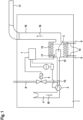
- Fig. 1 shows, by way of example and schematically, a heating device 1 proposed here.
- This can have an air supply 4 for combustion air.
- a gas-air mixing device 15 can be arranged in the air supply 4.
- a conveying device 2 designed as a fan can be arranged upstream of the gas-air mixing device 15, which can convey a mass flow of combustion air.
- a gas valve 5 can, by means of the gas-air mixing device 15, add a mass flow of fuel gas to the mass flow of combustion air conveyed by the conveying device 2.
- the gas valve can be connected to a gas supply 8.
- the mixture of fuel gas and combustion air can be fed to a burner 3 via a mixture channel 12 and burned there.
- a heat exchanger 13 can be arranged on the burner 3, which can transfer heat generated during combustion to a heating circuit 14 with a supply line 6 and a return line 9.
- an exhaust pipe 10 Downstream of the burner 3, an exhaust pipe 10 can feed combustion products to an exhaust system 11.
- a regulating and control device 7 of the heating device 1 can be electrically connected at least to the gas valve 5 and the conveying device 2.
- An ignition electrode 17 can be arranged on the burner 3, designed to form an ignition spark in order to ignite the combustion mixture emerging from the burner 3.
- Fig. 2 shows, by way of example and schematically, a longitudinal section in the direction of the central axis 21 of the gas-air mixing device 15. This comprises a trumpet-shaped convergence region 18 with a length 23. Seen in the flow direction 16, the convergence region 23 is followed by the throttle region 19 with a length 24 and with a minimum diameter 22 of the flow cross section.
- a divergence region 20 can be connected to the throttle region 19. This can have a length 25 of 85 mm and an opening angle 26 of 5.5°.
- a connection region 28 for connection to a silencer of the heater 1 can be provided on the outside in the convergence region 18 or in the throttle region 19.
- the gas-air mixing device 15 can comprise gas outlets 27. These can add a mass flow of fuel gas provided by the gas valve 5 to the mass flow of combustion air conveyed by the conveying device 2 and flowing through the gas-air mixing device 15.
- Fig. 3 shows, by way of example and schematically, a top view of the convergence region 18 of the gas-air mixing device 15.
- Three gas outlets 27 are clearly visible and evenly distributed over the circumference.
- the gas outlets 27 can enclose an angle 31, which is a measure of the width of the gas outlets 27.
- Fig. 4 shows an example and schematically a sectional view of a gas outlet 27. This can have a channel depth 30 and a wall thickness of the inner wall 29.
- first primarily serve (only) to distinguish between several similar objects, sizes or processes, and in particular do not necessarily specify a dependency and/or sequence of these objects, sizes or processes. If a dependency and/or sequence is required, this is explicitly stated here or it is obvious to the person skilled in the art when studying the specifically described design. If a component can occur multiple times (“at least one"), the description of one of these components can apply equally to all or part of the majority of these components, but this is not mandatory.
Landscapes
- Engineering & Computer Science (AREA)
- Chemical & Material Sciences (AREA)
- Combustion & Propulsion (AREA)
- Mechanical Engineering (AREA)
- General Engineering & Computer Science (AREA)
- Gas Burners (AREA)
- Furnace Details (AREA)
Applications Claiming Priority (1)
| Application Number | Priority Date | Filing Date | Title |
|---|---|---|---|
| DE102023111888.9A DE102023111888A1 (de) | 2023-05-08 | 2023-05-08 | Gas-Luft-Mischeinrichtung für ein Heizgerät und Heizgerät |
Publications (2)
| Publication Number | Publication Date |
|---|---|
| EP4462023A2 true EP4462023A2 (fr) | 2024-11-13 |
| EP4462023A3 EP4462023A3 (fr) | 2024-12-25 |
Family
ID=91022636
Family Applications (1)
| Application Number | Title | Priority Date | Filing Date |
|---|---|---|---|
| EP24174062.0A Pending EP4462023A3 (fr) | 2023-05-08 | 2024-05-03 | Dispositif de mélange gaz-air pour un appareil de chauffage et appareil de chauffage |
Country Status (2)
| Country | Link |
|---|---|
| EP (1) | EP4462023A3 (fr) |
| DE (1) | DE102023111888A1 (fr) |
Citations (3)
| Publication number | Priority date | Publication date | Assignee | Title |
|---|---|---|---|---|
| EP0846916A2 (fr) | 1996-12-06 | 1998-06-10 | SIT LA PRECISA S.r.l. | Dispositif de mélange air-gaz notamment pour brûleurs à air soufflé |
| DE102011014117A1 (de) | 2011-03-15 | 2012-09-20 | Ebm-Papst Landshut Gmbh | Mischvorrichtung zur Mischung von Verbrennungsluft und Gas für ein Gasgerät |
| EP3488148B1 (fr) | 2016-07-22 | 2021-02-17 | EBM-PAPST Landshut GmbH | Dispositif de mélange pour gaz-air |
Family Cites Families (3)
| Publication number | Priority date | Publication date | Assignee | Title |
|---|---|---|---|---|
| WO1992019920A1 (fr) * | 1989-11-06 | 1992-11-12 | Bruno Coussement | Chaudiere de chauffage central et/ou de production d'eau chaude sanitaire, bruleur pour combustible gazeux, et installation de chauffage central et de production d'eau chaude sanitaire utilisant ladite chaudiere |
| JP6625925B2 (ja) * | 2016-04-06 | 2019-12-25 | リンナイ株式会社 | 予混合装置 |
| DE102020202950A1 (de) * | 2020-03-06 | 2021-09-09 | Robert Bosch Gesellschaft mit beschränkter Haftung | Brenner zum Verbrennen eines Brennstoff-Luft-Gemischstroms sowie Heizgerät mit einem solchen Brenner |
-
2023
- 2023-05-08 DE DE102023111888.9A patent/DE102023111888A1/de active Pending
-
2024
- 2024-05-03 EP EP24174062.0A patent/EP4462023A3/fr active Pending
Patent Citations (3)
| Publication number | Priority date | Publication date | Assignee | Title |
|---|---|---|---|---|
| EP0846916A2 (fr) | 1996-12-06 | 1998-06-10 | SIT LA PRECISA S.r.l. | Dispositif de mélange air-gaz notamment pour brûleurs à air soufflé |
| DE102011014117A1 (de) | 2011-03-15 | 2012-09-20 | Ebm-Papst Landshut Gmbh | Mischvorrichtung zur Mischung von Verbrennungsluft und Gas für ein Gasgerät |
| EP3488148B1 (fr) | 2016-07-22 | 2021-02-17 | EBM-PAPST Landshut GmbH | Dispositif de mélange pour gaz-air |
Also Published As
| Publication number | Publication date |
|---|---|
| DE102023111888A1 (de) | 2024-11-14 |
| EP4462023A3 (fr) | 2024-12-25 |
Similar Documents
| Publication | Publication Date | Title |
|---|---|---|
| EP2014979A2 (fr) | Dispositif de fonctionnement pour un brûleur de surface haute performance et son procédé de fonctionnement | |
| CH703571B1 (de) | Brennstoffdüsenanordnung mit einer Mehrzonenbrennstoffdüse. | |
| DE2747678A1 (de) | Treibstoffduese fuer gasturbinen | |
| EP3957910B1 (fr) | Procédé et agencement de formation pneumatique d'un mélange dans un brûleur de prémélange | |
| EP0719983A1 (fr) | Procédé et dispositif d'alimentation du combustible gazeuse vers un brûleur à prémélange | |
| EP0175875A1 (fr) | Brûleur à huile ou à gaz pour la génération de gaz à chaud | |
| DE2552374A1 (de) | Brenner fuer fluessigen oder gasfoermigen brennstoff | |
| EP4008955B1 (fr) | Dispositif et procédé d'alimentation en air de combustion et de récirculation des gaz d'échappement pour un brûleur | |
| DE69603715T2 (de) | Venturi mischvorrichtung | |
| DE102016118633A1 (de) | Brennerkopf, Brennersystem und Verwendung des Brennersystems | |
| DE1932881A1 (de) | Brennkammer | |
| EP4462023A2 (fr) | Dispositif de mélange gaz-air pour un appareil de chauffage et appareil de chauffage | |
| EP3663669A1 (fr) | Module de chambre de combustion | |
| EP3250857B1 (fr) | Agencement de brûleur | |
| DE102024103166A1 (de) | Heizgerät mit einer Gas-Luft-Mischeinrichtung | |
| DE102005004844A1 (de) | Luft/Gas-Brenner-System | |
| DE2700786B2 (de) | Keramischer Gasbrenner für Winderhitzer | |
| EP4450874A1 (fr) | Appareil de chauffage avec un assemblage air-gaz pneumatique et procédé pour faire fonctionner un appareil de chauffage | |
| DE102016118632A1 (de) | Brennkammersystem, Verwendung eines Brennkammersystems mit einer angeschlossenen Turbine und Verfahren zur Durchführung eines Verbrennungsprozesses | |
| DE19824719C2 (de) | Brenner, insbesondere Ölbrenner | |
| DE19503781A1 (de) | Öl- oder Gasgebläsebrenner | |
| WO2003076846A1 (fr) | Bruleur destine notamment a des combustibles liquides ou gazeux | |
| EP2335816A2 (fr) | Dispositif de mélange de flux chauds | |
| EP4443052A1 (fr) | Appareil de chauffage et utilisation d'un élément de liaison | |
| DE3304214A1 (de) | Brenner zum einbau in heizungs- und dampferzeugungs anlagen |
Legal Events
| Date | Code | Title | Description |
|---|---|---|---|
| PUAI | Public reference made under article 153(3) epc to a published international application that has entered the european phase |
Free format text: ORIGINAL CODE: 0009012 |
|
| STAA | Information on the status of an ep patent application or granted ep patent |
Free format text: STATUS: THE APPLICATION HAS BEEN PUBLISHED |
|
| AK | Designated contracting states |
Kind code of ref document: A2 Designated state(s): AL AT BE BG CH CY CZ DE DK EE ES FI FR GB GR HR HU IE IS IT LI LT LU LV MC ME MK MT NL NO PL PT RO RS SE SI SK SM TR |
|
| PUAL | Search report despatched |
Free format text: ORIGINAL CODE: 0009013 |
|
| AK | Designated contracting states |
Kind code of ref document: A3 Designated state(s): AL AT BE BG CH CY CZ DE DK EE ES FI FR GB GR HR HU IE IS IT LI LT LU LV MC ME MK MT NL NO PL PT RO RS SE SI SK SM TR |
|
| RIC1 | Information provided on ipc code assigned before grant |
Ipc: F23D 14/62 20060101ALI20241120BHEP Ipc: F23D 14/60 20060101AFI20241120BHEP |
|
| STAA | Information on the status of an ep patent application or granted ep patent |
Free format text: STATUS: REQUEST FOR EXAMINATION WAS MADE |
|
| 17P | Request for examination filed |
Effective date: 20250625 |