EP4462143A1 - Batteriediagnosevorrichtung und -verfahren - Google Patents
Batteriediagnosevorrichtung und -verfahren Download PDFInfo
- Publication number
- EP4462143A1 EP4462143A1 EP23816263.0A EP23816263A EP4462143A1 EP 4462143 A1 EP4462143 A1 EP 4462143A1 EP 23816263 A EP23816263 A EP 23816263A EP 4462143 A1 EP4462143 A1 EP 4462143A1
- Authority
- EP
- European Patent Office
- Prior art keywords
- battery
- resistance
- diagnosing
- discharge
- change rate
- Prior art date
- Legal status (The legal status is an assumption and is not a legal conclusion. Google has not performed a legal analysis and makes no representation as to the accuracy of the status listed.)
- Pending
Links
Images



Classifications
-
- B—PERFORMING OPERATIONS; TRANSPORTING
- B60—VEHICLES IN GENERAL
- B60L—PROPULSION OF ELECTRICALLY-PROPELLED VEHICLES; SUPPLYING ELECTRIC POWER FOR AUXILIARY EQUIPMENT OF ELECTRICALLY-PROPELLED VEHICLES; ELECTRODYNAMIC BRAKE SYSTEMS FOR VEHICLES IN GENERAL; MAGNETIC SUSPENSION OR LEVITATION FOR VEHICLES; MONITORING OPERATING VARIABLES OF ELECTRICALLY-PROPELLED VEHICLES; ELECTRIC SAFETY DEVICES FOR ELECTRICALLY-PROPELLED VEHICLES
- B60L58/00—Methods or circuit arrangements for monitoring or controlling batteries or fuel cells, specially adapted for electric vehicles
- B60L58/10—Methods or circuit arrangements for monitoring or controlling batteries or fuel cells, specially adapted for electric vehicles for monitoring or controlling batteries
- B60L58/16—Methods or circuit arrangements for monitoring or controlling batteries or fuel cells, specially adapted for electric vehicles for monitoring or controlling batteries responding to battery ageing, e.g. to the number of charging cycles or the state of health [SoH]
-
- G—PHYSICS
- G01—MEASURING; TESTING
- G01R—MEASURING ELECTRIC VARIABLES; MEASURING MAGNETIC VARIABLES
- G01R19/00—Arrangements for measuring currents or voltages or for indicating presence or sign thereof
- G01R19/10—Measuring sum, difference or ratio
-
- G—PHYSICS
- G01—MEASURING; TESTING
- G01R—MEASURING ELECTRIC VARIABLES; MEASURING MAGNETIC VARIABLES
- G01R29/00—Arrangements for measuring or indicating electric quantities not covered by groups G01R19/00 - G01R27/00
- G01R29/02—Measuring characteristics of individual pulses, e.g. deviation from pulse flatness, rise time or duration
-
- G—PHYSICS
- G01—MEASURING; TESTING
- G01R—MEASURING ELECTRIC VARIABLES; MEASURING MAGNETIC VARIABLES
- G01R31/00—Arrangements for testing electric properties; Arrangements for locating electric faults; Arrangements for electrical testing characterised by what is being tested not provided for elsewhere
- G01R31/36—Arrangements for testing, measuring or monitoring the electrical condition of accumulators or electric batteries, e.g. capacity or state of charge [SoC]
- G01R31/378—Arrangements for testing, measuring or monitoring the electrical condition of accumulators or electric batteries, e.g. capacity or state of charge [SoC] specially adapted for the type of battery or accumulator
-
- G—PHYSICS
- G01—MEASURING; TESTING
- G01R—MEASURING ELECTRIC VARIABLES; MEASURING MAGNETIC VARIABLES
- G01R31/00—Arrangements for testing electric properties; Arrangements for locating electric faults; Arrangements for electrical testing characterised by what is being tested not provided for elsewhere
- G01R31/36—Arrangements for testing, measuring or monitoring the electrical condition of accumulators or electric batteries, e.g. capacity or state of charge [SoC]
- G01R31/382—Arrangements for monitoring battery or accumulator variables, e.g. SoC
- G01R31/3835—Arrangements for monitoring battery or accumulator variables, e.g. SoC involving only voltage measurements
-
- G—PHYSICS
- G01—MEASURING; TESTING
- G01R—MEASURING ELECTRIC VARIABLES; MEASURING MAGNETIC VARIABLES
- G01R31/00—Arrangements for testing electric properties; Arrangements for locating electric faults; Arrangements for electrical testing characterised by what is being tested not provided for elsewhere
- G01R31/36—Arrangements for testing, measuring or monitoring the electrical condition of accumulators or electric batteries, e.g. capacity or state of charge [SoC]
- G01R31/389—Measuring internal impedance, internal conductance or related variables
-
- G—PHYSICS
- G01—MEASURING; TESTING
- G01R—MEASURING ELECTRIC VARIABLES; MEASURING MAGNETIC VARIABLES
- G01R31/00—Arrangements for testing electric properties; Arrangements for locating electric faults; Arrangements for electrical testing characterised by what is being tested not provided for elsewhere
- G01R31/36—Arrangements for testing, measuring or monitoring the electrical condition of accumulators or electric batteries, e.g. capacity or state of charge [SoC]
- G01R31/392—Determining battery ageing or deterioration, e.g. state of health
-
- H—ELECTRICITY
- H01—ELECTRIC ELEMENTS
- H01M—PROCESSES OR MEANS, e.g. BATTERIES, FOR THE DIRECT CONVERSION OF CHEMICAL ENERGY INTO ELECTRICAL ENERGY
- H01M10/00—Secondary cells; Manufacture thereof
- H01M10/05—Accumulators with non-aqueous electrolyte
- H01M10/052—Li-accumulators
-
- H—ELECTRICITY
- H01—ELECTRIC ELEMENTS
- H01M—PROCESSES OR MEANS, e.g. BATTERIES, FOR THE DIRECT CONVERSION OF CHEMICAL ENERGY INTO ELECTRICAL ENERGY
- H01M10/00—Secondary cells; Manufacture thereof
- H01M10/42—Methods or arrangements for servicing or maintenance of secondary cells or secondary half-cells
- H01M10/425—Structural combination with electronic components, e.g. electronic circuits integrated to the outside of the casing
-
- H—ELECTRICITY
- H01—ELECTRIC ELEMENTS
- H01M—PROCESSES OR MEANS, e.g. BATTERIES, FOR THE DIRECT CONVERSION OF CHEMICAL ENERGY INTO ELECTRICAL ENERGY
- H01M10/00—Secondary cells; Manufacture thereof
- H01M10/42—Methods or arrangements for servicing or maintenance of secondary cells or secondary half-cells
- H01M10/48—Accumulators combined with arrangements for measuring, testing or indicating the condition of cells, e.g. the level or density of the electrolyte
-
- H—ELECTRICITY
- H01—ELECTRIC ELEMENTS
- H01M—PROCESSES OR MEANS, e.g. BATTERIES, FOR THE DIRECT CONVERSION OF CHEMICAL ENERGY INTO ELECTRICAL ENERGY
- H01M10/00—Secondary cells; Manufacture thereof
- H01M10/42—Methods or arrangements for servicing or maintenance of secondary cells or secondary half-cells
- H01M10/44—Methods for charging or discharging
-
- H—ELECTRICITY
- H01—ELECTRIC ELEMENTS
- H01M—PROCESSES OR MEANS, e.g. BATTERIES, FOR THE DIRECT CONVERSION OF CHEMICAL ENERGY INTO ELECTRICAL ENERGY
- H01M2220/00—Batteries for particular applications
- H01M2220/20—Batteries in motive systems, e.g. vehicle, ship, plane
-
- Y—GENERAL TAGGING OF NEW TECHNOLOGICAL DEVELOPMENTS; GENERAL TAGGING OF CROSS-SECTIONAL TECHNOLOGIES SPANNING OVER SEVERAL SECTIONS OF THE IPC; TECHNICAL SUBJECTS COVERED BY FORMER USPC CROSS-REFERENCE ART COLLECTIONS [XRACs] AND DIGESTS
- Y02—TECHNOLOGIES OR APPLICATIONS FOR MITIGATION OR ADAPTATION AGAINST CLIMATE CHANGE
- Y02E—REDUCTION OF GREENHOUSE GAS [GHG] EMISSIONS, RELATED TO ENERGY GENERATION, TRANSMISSION OR DISTRIBUTION
- Y02E60/00—Enabling technologies; Technologies with a potential or indirect contribution to GHG emissions mitigation
- Y02E60/10—Energy storage using batteries
Definitions
- the present disclosure relates to an apparatus and method for diagnosing a battery, and more particularly, to an apparatus and method for diagnosing a battery, which is capable of diagnosing a battery state.
- Batteries commercially available at present include nickel-cadmium batteries, nickel hydrogen batteries, nickel-zinc batteries, lithium batteries and the like.
- the lithium batteries are in the limelight since they have almost no memory effect compared to nickel-based batteries and also have very low self-charging rate and high energy density.
- lithium precipitation on the surface of the negative electrode lithium plating, Li-plating
- lithium precipitates on the surface of the negative electrode it causes side reactions with the electrolyte and changes in the kinetic balance of the battery, causing battery deterioration.
- an internal short circuit of the battery may occur, so there is a risk of ignition or explosion due to an internal short circuit. Therefore, there is a need to develop a technology that can detect whether lithium metal has been precipitated on the surface of the negative electrode.
- the present disclosure is designed to solve the problems of the related art, and therefore the present disclosure is directed to providing an apparatus and method for diagnosing a battery, which is capable of diagnosing lithium precipitation in the battery.
- An apparatus for diagnosing a battery may comprise a voltage measuring unit configured to measure a voltage of a battery during a discharge process of the battery; a pulse output unit configured to generate a discharge pulse at every predetermined cycle and output the generated discharge pulse to the battery; and a control unit configured to calculate a resistance value of the battery based on a voltage deviation of the battery due to the discharge pulse, determine a resistance pattern in a preset initial discharge region based on the calculated resistance value, and diagnose whether there is lithium precipitation in the battery according to the determined resistance pattern.
- the control unit may be configured to calculate a resistance change rate for a plurality of target resistance values included in the initial discharge region, compare the calculated resistance change rate with a preset criterion change rate, and determine the resistance pattern as a first resistance pattern or a second resistance pattern based on the comparison result.
- the control unit may be configured to calculate an average change rate for the plurality of target resistance values included in the initial discharge region, and calculate the calculated average change rate as the resistance change rate.
- the control unit may be configured to determine the resistance pattern as the first resistance pattern when the calculated resistance change rate is less than the criterion change rate.
- the control unit may be configured to determine the resistance pattern as the second resistance pattern when the calculated resistance change rate is equal to or greater than the criterion change rate.
- the control unit may be configured to diagnose that lithium has been precipitated in the battery when the resistance pattern is the first resistance pattern.
- the pulse output unit may be configured to output the discharge pulse at a discharge start point where discharge of the battery begins.
- the initial discharge region may be preset as a region from a discharge start point where discharge of the battery begins to a target point.
- the target point may be preset as a point corresponding to a minimum resistance value from the start point in a criterion profile preset to correspond to the battery.
- the control unit may be configured to calculate the resistance value of the battery at each predetermined cycle based on a current amount corresponding to the discharge pulse and the voltage deviation.
- a battery pack according to another aspect of the present disclosure may comprise the apparatus for diagnosing a battery according to one aspect of the present disclosure.
- a vehicle according to still another aspect of the present disclosure may comprise the apparatus for diagnosing a battery according to one aspect of the present disclosure.
- a method for diagnosing a battery may comprise a voltage measuring step of measuring a voltage of a battery during a discharge process of the battery; a discharge pulse output step of generating a discharge pulse at every predetermined cycle and outputting the generated discharge pulse to the battery; a resistance value calculating step of calculating a resistance value of the battery based on a voltage deviation of the battery due to the discharge pulse; a resistance pattern determining step of determining a resistance pattern in a preset initial discharge region based on the calculated resistance value; and a diagnosing step of judging whether there is lithium precipitation in the battery according to the determined resistance pattern.
- the apparatus for diagnosing a battery has an advantage of diagnosing the state of the battery based on the resistance change rate of the battery in the initial discharge region.
- the apparatus for diagnosing a battery has an advantage of quickly diagnosing lithium precipitation in the battery by calculating the resistance value at the initial discharge point of the battery.
- the diagnosis is performed in the discharge process of the battery, that is, the diagnosis is performed in the process of reducing the battery's energy, there is an advantage in that lithium precipitation in the battery can be safely diagnosed.
- FIG. 1 is a diagram schematically illustrating an apparatus 100 for diagnosing a battery according to an embodiment of the present disclosure.
- the apparatus 100 for diagnosing a battery may include a voltage measuring unit 110, a pulse output unit 120, and a control unit 130.
- the battery means one physically separable independent cell having a negative electrode terminal and a positive electrode terminal.
- a lithium-ion battery or a lithium polymer battery may be regarded as a battery.
- the battery may mean a battery module in which a plurality of cells are connected in series and/or parallel.
- a battery will be described as meaning one independent cell.
- the voltage measuring unit 110 may be configured to measure the voltage of the battery during the discharge process of the battery.
- the voltage measuring unit 110 may measure the voltage of the battery in the discharge process of the battery at each voltage measurement cycle.
- the pulse output unit 120 may be configured to generate a discharge pulse at every predetermined cycle.
- the pulse output unit 120 may be configured to generate a discharge pulse at every predetermined cycle when receiving a pulse generation signal from the control unit 130. Also, when the pulse output unit 120 receives a pulse generation end signal from the control unit 130, the pulse output unit 120 may stop generating discharge pulses.
- the pulse output unit 120 may generate a DC pulse (Direct current pulse) at every predetermined cycle.
- the pulse output unit 120 may generate an AC pulse (Alternating current pulses) at every predetermined cycle.
- the pulse output unit 120 may be configured to output the generated discharge pulse to the battery.
- the pulse output unit 120 may output a discharge pulse to the negative electrode of the battery through the pulse line PL. More specifically, the pulse output unit 120 may output a discharge pulse to the negative electrode of the battery to correspond to the discharge direction of the battery.
- the pulse output unit 120 may be configured to output a discharge pulse at a discharge start point where discharge of the battery begins.
- the pulse output unit 120 may output a discharge pulse at the same time that the battery starts discharging.
- the battery state diagnosis result can be a highly reliable result that better reflects the state of the battery.
- FIG. 2 is a diagram schematically illustrating a discharge pulse according to an embodiment of the present disclosure.
- the pulse output unit 120 may generate and output a discharge pulse with a current value of k [mA] at every predetermined cycle T.
- the discharge pulse generated by the pulse output unit 120 may be the same.
- the current amount of the discharge pulse may be the same.
- the pulse output unit 120 may output a discharge pulse of 0.1 seconds at every minute.
- the predetermined cycle T in which the discharge pulse is output may be 1 minute, and a discharge pulse of 0.1 seconds may be output at each cycle.
- t0 at which discharge pulses begin to be output may be the same as the time when discharge of the battery begins.
- the pulse output unit 120 may output a discharge pulse at the time point t0 when the battery begins to discharge. Therefore, battery discharge and discharge pulse output can begin simultaneously.
- the control unit 130 may be configured to calculate the resistance value of the battery based on the voltage deviation of the battery caused by the discharge pulse.
- control unit 130 may calculate the internal resistance value of the battery based on the discharge pulse applied to the battery being discharged.
- control unit 130 may be configured to calculate the resistance value of the battery at each predetermined cycle based on the current amount corresponding to the discharge pulse and the voltage deviation.
- the current amount of the discharge pulse can be calculated in the same way.
- the time at which the discharge pulse is applied is ⁇ t
- the current amount of the discharge pulse can be calculated as "k ⁇ ⁇ t".
- ⁇ t may be the time difference between t0 and t1, t2 and t3, or t4 and t5.
- the pulse output unit 120 outputs a discharge pulse of 0.1 seconds at every minute
- ⁇ t may be 0.1 seconds
- T may be 60 seconds.
- control unit 130 may calculate the voltage deviation of the battery according to the discharge pulse by calculating the difference between the voltage of the battery at the start point of the discharge pulse and the voltage of the battery at the end point of the discharge pulse. For example, in the embodiment of FIG. 2 , the control unit 130 may calculate the voltage deviation by calculating the difference between the voltage of the battery at time t0 and the voltage of the battery at time 11.
- R may be the resistance value
- ⁇ V may be the voltage deviation
- ⁇ I may be the current amount.
- the control unit 130 may be configured to determine a resistance pattern in a preset initial discharge region based on the calculated resistance value.
- control unit 130 may calculate a plurality of resistance values while the battery is being discharged. Additionally, the initial discharge region may include a plurality of resistance values calculated by the control unit 130.
- the initial discharge region refers to the time interval from the discharge start point to a predetermined time. Specific details about the initial discharge region will be described later.
- control unit 130 may be configured to calculate the resistance change rate for the plurality of target resistance values included in the initial discharge region.
- the target resistance value may refer to a resistance value belonging to the initial discharge region among the plurality of resistance values calculated by the control unit 130.
- control unit 130 may be configured to calculate an average change rate for the plurality of target resistance values included in the initial discharge region. Additionally, the control unit 130 may be configured to calculate the calculated average change rate as the resistance change rate.
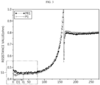
- FIG. 3 is a diagram schematically showing a criterion profile PR1 and a resistance profile P1 of a first battery according to an embodiment of the present disclosure.
- FIG. 4 is an enlarged view showing the area S1 in FIG. 3 .
- the area S1 may be an enlarged view of a partial area in the criterion profile PR1 and the resistance profile P1.
- the criterion profile PR1 and the resistance profile P1 may be profiles representing the correspondence between resistance value and time.
- the criterion profile PR1 may be a preset profile for the first battery in a BOL (Beginning of life) state or a criterion battery for the first battery.
- the resistance profile P1 may be a profile created by the control unit during the discharge process of the first battery. That is, the resistance profile P1 may be a profile showing the resistance value calculated by the control unit over time.
- control unit 130 may calculate the resistance value of the first battery at every predetermined cycle T during the discharge process of the first battery. Additionally, the control unit 130 may calculate the average change rate in the initial discharge region D1. Specifically, the control unit 130 may calculate the resistance value change rate according to time at the initial discharge point (0 seconds) and time 11.
- the control unit 130 may calculate the resistance change rate for the first battery by calculating the formula "(r4 - r3) ⁇ (t1 - 0)".
- the resistance change rate for the first battery may be 0.
- the control unit 130 may be configured to compare the calculated resistance change rate with a preset criterion change rate.
- the control unit 130 may compare the magnitude between the calculated resistance change rate and the preset criterion change rate. That is, the control unit 130 may determine whether the calculated resistance change rate is less than or more than the criterion change rate.
- the criterion change rate is a resistance change rate that is a criterion for determining the resistance pattern of the battery, and may be set in advance.
- the criterion change rate may be preset to 0.
- the criterion change rate may be preset to any value in the range of 0 or more and less than the resistance change rate according to the criterion profile PR1.
- the criterion change rate may be preset to "0" or "any one value greater than 0 and less than (r2 - r1) ⁇ (t1 - 0)."
- “(r2 - r1) ⁇ (t1 - 0)" is the resistance change rate for the first resistance profile PR1.
- the control unit 130 may be configured to determine the resistance pattern as a first resistance pattern or a second resistance pattern based on the comparison result. Preferably, the control unit 130 may be configured to determine the resistance pattern as the first resistance pattern if the calculated resistance change rate is less than the criterion change rate. Conversely, the control unit 130 may be configured to determine the resistance pattern as the second resistance pattern if the calculated resistance change rate is greater than or equal to the criterion change rate.
- control unit 130 may determine the resistance pattern of the first battery as the second resistance pattern.
- the control unit 130 may be configured to judge whether there is lithium precipitation in the battery according to the determined resistance pattern.
- control unit 130 may be configured to diagnose that lithium precipitation has occurred in the battery if the resistance pattern is the first resistance pattern. Conversely, the control unit 130 may diagnose that lithium has not been precipitated in the battery if the resistance pattern is the second resistance pattern.
- the control unit 130 may diagnose that lithium metal is not precipitated in the first battery.
- the apparatus 100 for diagnosing a battery has an advantage of diagnosing the state of the battery based on the resistance change rate of the battery in the initial discharge region.
- the apparatus 100 for diagnosing a battery has an advantage of quickly diagnosing lithium precipitation in the battery by calculating the resistance value at the initial discharge point of the battery.
- the diagnosis is performed during the discharge process of the battery, that is, during the process in which the energy of the battery is reduced, there is an advantage that lithium precipitation in the battery can be safely diagnosed.
- control unit 130 included in the apparatus 100 for diagnosing a battery may optionally include processors, application-specific integrated circuits (ASICs), other chipsets, logic circuits, registers, communication modems, data processing devices, etc. known in the art to execute various control logics performed in the present disclosure.
- control logic when the control logic is implemented as software, the control unit 130 may be implemented as a set of program modules.
- the program module may be stored in the memory and executed by the control unit 130.
- the memory may be inside or outside the control unit 130 and may be connected to the control unit 130 by various well-known means.
- the apparatus 100 for diagnosing a battery may further include a storage unit 140.
- the storage unit 140 may store data necessary for operation and function of each component of the apparatus 100 for diagnosing a battery, data generated in the process of performing the operation or function, or the like.
- the storage unit 140 is not particularly limited in its kind as long as it is a known information storage means that can record, erase, update and read data.
- the information storage means may include RAM, flash memory, ROM, EEPROM, registers, and the like.
- the storage unit 140 may store program codes in which processes executable by the control unit 130 are defined.
- the criterion profile and the criterion change rate corresponding to the battery may be stored in advance in the storage unit 140. Additionally, the control unit 130 may access the storage unit 140 to obtain the criterion profile and the criterion change rate. Additionally, the voltage value measured by the voltage measuring unit 110 may be stored in the storage unit 140.
- FIG. 5 is a diagram schematically showing a criterion profile PR2 and a resistance profile P2 of a second battery according to an embodiment of the present disclosure.
- FIG. 6 is an enlarged view showing the area S2 in FIG. 5 .
- the area S2 may be an enlarged view of a partial area of the criterion profile PR2 and the resistance profile P2.
- the control unit 130 may calculate the resistance change rate for the second battery by calculating the formula "(r4 - r3) ⁇ (t2 - 0)".
- the resistance change rate for the second battery can be calculated as a positive number. If the criterion change rate for the second battery is set to 0, the calculated resistance change rate may be greater than the criterion change rate. Therefore, the control unit 130 may determine the resistance pattern for the second battery as the second resistance pattern based on the comparison result. Also, the control unit 130 may diagnose that lithium is not precipitated in the second battery based on the determined resistance pattern.
- the initial discharge region can be set in advance from the discharge start point where battery discharge begins, to the target point.
- the first initial discharge region D1 for the first battery may be preset to 0 to t1.
- the second initial discharge region D2 for the second battery may be preset to 0 to t2.
- the initial discharge region represents a time interval for diagnosing the state of the battery, it can be independently set to correspond to the battery. If the initial discharge region is set uniformly without considering the type of battery, etc., the battery resistance change rate indicated in the initial discharge region may not accurately represent the state of the battery. Therefore, the initial discharge region can be set to correspond to each battery.
- the target point may be preset from the start point to the time point corresponding to the minimum resistance value in the criterion profile preset to correspond to the battery.
- the target point may be t1.
- the resistance value at the discharge start point (0 seconds) may be r1
- the minimum resistance value may be r2. Therefore, the target point may be 11, which is the time point corresponding to the minimum resistance value r2.
- the initial discharge region D1 for the first battery may be the time interval from the discharge start point (0 seconds) to the target point t1. In other words, lithium precipitation in the first battery can be seen best in the time from 0 seconds to t1 seconds. Therefore, the control unit 130 can more accurately diagnose whether there is lithium precipitation in the first battery according to the resistance change rate of the first battery in the initial discharge region D1.
- the target point may be t2.
- the resistance value at the discharge start point (0 seconds) may be r1
- the minimum resistance value may be r2. Therefore, the target point may be t2, which is the time point corresponding to the minimum resistance value r2.
- the initial discharge region D2 for the second battery may be the time interval from the discharge start point (0 seconds) to the target point t2. In other words, lithium precipitation in the second battery can be seen best in the time from 0 seconds to t2 seconds. Therefore, the control unit 130 can more accurately diagnose whether there is lithium precipitation in the second battery according to the resistance change rate of the second battery in the initial discharge region D2.
- the apparatus 100 for diagnosing a battery according to an embodiment of the present disclosure can accurately diagnose lithium precipitation in the battery according to the resistance change rate in the initial discharge region set for each battery.
- the apparatus 100 for diagnosing a battery since the initial discharge region in which lithium precipitation can be accurately diagnosed can be set for each battery according to the resistance change rate of the battery at the beginning of discharge, the apparatus 100 for diagnosing a battery has an advantage of more accurately diagnosing lithium precipitation in the battery.
- lithium precipitation can be immediately diagnosed according to the resistance change rate at the beginning of discharge, there is an advantage that the state of the battery can be quickly diagnosed.
- the apparatus 100 for diagnosing a battery according to the present disclosure may be applied to a battery management system (BMS). That is, the BMS according to the present disclosure may include the apparatus 100 for diagnosing a battery described above. In this configuration, at least some of components of the apparatus 100 for diagnosing a battery may be implemented by supplementing or adding functions of the components included in a conventional BMS. For example, the voltage measuring unit 110, the pulse output unit 120, the control unit 130 and the storage unit 140 of the apparatus 100 for diagnosing a battery may be implemented as components of the BMS.
- the apparatus 100 for diagnosing a battery according to the present disclosure may be provided to a battery pack. That is, the battery pack according to the present disclosure may include the above-described apparatus 100 for diagnosing a battery and one or more battery cells. In addition, the battery pack may further include electrical components (a relay, a fuse and the like) and a case.
- FIG. 7 is a diagram schematically showing an exemplary configuration of a battery pack according to another embodiment of the present disclosure.
- the positive electrode terminal of the battery B may be connected to the positive electrode terminal P+ of the battery pack 10, and the negative electrode terminal of the battery B may be connected to the negative electrode terminal P- of the battery pack 10.
- the voltage measuring unit 10 may be connected to the first sensing line SL1 and the second sensing line SL2. Specifically, the voltage measuring unit 110 may be connected to the positive electrode terminal of the battery B through the first sensing line SL1, and may be connected to the negative electrode terminal of the battery B through the second sensing line SL2. The voltage measuring unit 110 may measure the voltage of the battery B based on the voltage measured at each of the first sensing line SL1 and the second sensing line SL2.
- the voltage measuring unit 110 may measure the voltage of the battery B while the battery B is being discharged.
- the voltage measuring unit 110 may measure the voltage of the battery B even while a discharge pulse is applied to the battery B by the pulse output unit 120.
- the control unit 130 may calculate the resistance value of the battery B based on the voltage deviation of the battery B due to the discharge pulse.
- the load may be connected to the positive electrode terminal P+ of the battery pack 10, and the other end may be connected to the negative electrode terminal P- of the battery pack 10. Accordingly, the positive electrode terminal of the battery B, the positive electrode terminal P+ of the battery pack 10, the load, the negative electrode terminal P- of the battery pack 10, and the negative electrode terminal of the battery B can be electrically connected.
- the load may be a charging and discharging device, or a motor of an electric vehicle or the like that receives power from the battery B.
- FIG. 8 is a diagram schematically showing a vehicle 1 according to still another embodiment of the present disclosure.
- the apparatus for diagnosing a battery 100 may be included in a vehicle 1 such as an electric vehicle (EV) or a hybrid vehicle (HV).
- vehicle 1 such as an electric vehicle (EV) or a hybrid vehicle (HV).
- the apparatus for diagnosing a battery 100 may be included in the battery pack 10, and the battery pack 10 may be included in the vehicle 1.
- the battery pack may drive the vehicle 1 by supplying power to a motor through an inverter included in the vehicle 1.
- the apparatus 100 for diagnosing a battery can diagnose lithium precipitation in the battery cells included in the battery pack by outputting a discharge pulse.
- the battery state can be diagnosed even without a separate maintenance process, there is an advantage in that the battery state can be checked at any time. Also, if it is diagnosed that lithium has been precipitated in the battery, information about this can be provided immediately.
- FIG. 9 is a diagram schematically showing a method for diagnosing a battery according to still another embodiment of the present disclosure.
- each step of the method for diagnosing a battery may be performed by the apparatus 100 for diagnosing a battery.
- the content overlapping with the previously described content will be omitted or briefly described.
- the method for diagnosing a battery may include a voltage measuring step (S100), a discharge pulse output step (S200), a resistance value calculating step (S300), a resistance pattern determining step (S400), and a diagnosing step (S500).
- the discharge pulse output step (S200) is shown as being performed after the voltage measuring step (S100), but preferably, the voltage measuring step (S100) and the discharge pulse output step (S200) may be performed simultaneously.
- the voltage measuring step (S 100) is a step of measuring the voltage of the battery in the discharge process of the battery, and may be performed by the voltage measuring unit 110.
- the discharge pulse output step (S200) is a step of generating a discharge pulse at every predetermined cycle and outputting the generated discharge pulse to the battery, and may be performed by the pulse output unit 120.
- the voltage measuring unit 110 may measure the voltage of the battery during the discharge process of the battery.
- the voltage measuring unit 110 may measure the voltage of the battery even when a discharge pulse is applied to the battery.
- the output cycle T of the discharge pulse is preset to be equal to or greater than the voltage measurement cycle of the voltage measuring unit 110.
- the resistance value calculating step (S300) is a step of calculating the resistance value of the battery based on the voltage deviation of the battery due to the discharge pulse, and may be performed by the control unit 130.
- control unit 130 can know information about the discharge pulse in advance. That is, the control unit 130 can know the current amount ( ⁇ I) of the discharge pulse in advance. Therefore, the control unit 130 can calculate the resistance value R of the battery by considering the current amount ( ⁇ I) and the voltage deviation ( ⁇ V) of the battery according to the discharge pulse.
- the resistance pattern determining step (S400) is a step of determining the resistance pattern in a preset initial discharge region based on the calculated resistance value, and may be performed by the control unit 130.
- the control unit 130 may calculate the resistance change rate by calculating an average change rate for a plurality of target resistance values included in the initial discharge region. Additionally, the control unit 130 may compare the calculated resistance change rate with a preset criterion change rate to determine the resistance pattern.
- control unit 130 may determine the resistance pattern as the first resistance pattern. Conversely, the control unit 130 may determine the resistance pattern as the second resistance pattern if the calculated resistance change rate is greater than or equal to the criterion change rate.
- the diagnosing step (S500) is a step of judging whether or not there is lithium precipitation in the battery according to the determined resistance pattern, and may be performed by the control unit 130.
- control unit 130 may be configured to diagnose that lithium precipitation has occurred in the battery if the resistance pattern is the first resistance pattern. Conversely, the control unit 130 may diagnose that lithium has not been precipitated in the battery if the resistance pattern is the second resistance pattern.
- the embodiments of the present disclosure described above may not be implemented only through an apparatus and a method, but may be implemented through a program that realizes a function corresponding to the configuration of the embodiments of the present disclosure or a recording medium on which the program is recorded.
- the program or recording medium may be easily implemented by those skilled in the art from the above description of the embodiments.
Landscapes
- Engineering & Computer Science (AREA)
- General Physics & Mathematics (AREA)
- Physics & Mathematics (AREA)
- Chemical Kinetics & Catalysis (AREA)
- Chemical & Material Sciences (AREA)
- Electrochemistry (AREA)
- General Chemical & Material Sciences (AREA)
- Manufacturing & Machinery (AREA)
- Sustainable Development (AREA)
- Life Sciences & Earth Sciences (AREA)
- Sustainable Energy (AREA)
- Power Engineering (AREA)
- Transportation (AREA)
- Mechanical Engineering (AREA)
- Microelectronics & Electronic Packaging (AREA)
- Secondary Cells (AREA)
- Tests Of Electric Status Of Batteries (AREA)
Applications Claiming Priority (2)
| Application Number | Priority Date | Filing Date | Title |
|---|---|---|---|
| KR1020220066254A KR102877100B1 (ko) | 2022-05-30 | 2022-05-30 | 배터리 진단 장치 및 방법 |
| PCT/KR2023/006643 WO2023234600A1 (ko) | 2022-05-30 | 2023-05-16 | 배터리 진단 장치 및 방법 |
Publications (2)
| Publication Number | Publication Date |
|---|---|
| EP4462143A1 true EP4462143A1 (de) | 2024-11-13 |
| EP4462143A4 EP4462143A4 (de) | 2025-09-03 |
Family
ID=89025321
Family Applications (1)
| Application Number | Title | Priority Date | Filing Date |
|---|---|---|---|
| EP23816263.0A Pending EP4462143A4 (de) | 2022-05-30 | 2023-05-16 | Batteriediagnosevorrichtung und -verfahren |
Country Status (5)
| Country | Link |
|---|---|
| EP (1) | EP4462143A4 (de) |
| JP (1) | JP7806375B2 (de) |
| KR (1) | KR102877100B1 (de) |
| CN (1) | CN118829894A (de) |
| WO (1) | WO2023234600A1 (de) |
Family Cites Families (13)
| Publication number | Priority date | Publication date | Assignee | Title |
|---|---|---|---|---|
| JP4888577B2 (ja) * | 2010-04-12 | 2012-02-29 | トヨタ自動車株式会社 | 非水電解液型リチウムイオン二次電池システム,そのシステムにおけるリチウム析出判定方法,および,そのシステムを搭載する車両 |
| WO2014109271A1 (en) * | 2013-01-14 | 2014-07-17 | Semiconductor Energy Laboratory Co., Ltd. | Electrochemical device |
| CN105556323B (zh) * | 2013-10-29 | 2019-01-04 | 松下知识产权经营株式会社 | 电池状态估计装置 |
| KR101748643B1 (ko) * | 2014-12-24 | 2017-07-03 | 주식회사 엘지화학 | 배터리 팩의 측정 데이터 선별 장치 및 방법 |
| KR101998069B1 (ko) * | 2017-06-23 | 2019-07-09 | 이정환 | 전기자동차용 배터리의 열화 발생을 저감하면서 고속충전과 최대방전을 수행하기 위한 방법 및 그 장치 |
| JP7595642B2 (ja) | 2019-07-17 | 2024-12-06 | ズーマゲン バイオサイエンシーズ エルティーディー | Nlrp3モジュレーター |
| JP7395327B2 (ja) * | 2019-11-12 | 2023-12-11 | 日産自動車株式会社 | 二次電池に含まれるリチウムの析出を判定する判定装置及び判定方法 |
| KR102865368B1 (ko) * | 2019-12-11 | 2025-09-25 | 주식회사 엘지에너지솔루션 | 전극의 상대적 퇴화도를 이용한 이차 전지의 동작 제어 장치 및 방법 |
| US20230014689A1 (en) * | 2020-03-10 | 2023-01-19 | Mitsubishi Electric Corporation | Deterioration degree diagnosis device |
| CN112240983B (zh) * | 2020-09-22 | 2021-10-26 | 清华大学 | 电池析锂检测方法及其检测装置 |
| KR102892911B1 (ko) * | 2020-10-12 | 2025-11-27 | 주식회사 엘지에너지솔루션 | 배터리 진단 장치 및 방법 |
| JP7697200B2 (ja) * | 2020-10-30 | 2025-06-24 | 株式会社Gsユアサ | 推定装置、推定方法、及びコンピュータプログラム |
| JP7683553B2 (ja) * | 2021-12-24 | 2025-05-27 | 株式会社デンソー | 電池監視装置、電池輸送機器、電池監視方法 |
-
2022
- 2022-05-30 KR KR1020220066254A patent/KR102877100B1/ko active Active
-
2023
- 2023-05-16 CN CN202380025509.9A patent/CN118829894A/zh active Pending
- 2023-05-16 WO PCT/KR2023/006643 patent/WO2023234600A1/ko not_active Ceased
- 2023-05-16 EP EP23816263.0A patent/EP4462143A4/de active Pending
- 2023-05-16 JP JP2024544389A patent/JP7806375B2/ja active Active
Also Published As
| Publication number | Publication date |
|---|---|
| WO2023234600A1 (ko) | 2023-12-07 |
| JP7806375B2 (ja) | 2026-01-27 |
| CN118829894A (zh) | 2024-10-22 |
| KR20230166362A (ko) | 2023-12-07 |
| EP4462143A4 (de) | 2025-09-03 |
| JP2025503954A (ja) | 2025-02-06 |
| KR102877100B1 (ko) | 2025-10-24 |
Similar Documents
| Publication | Publication Date | Title |
|---|---|---|
| US20240044995A1 (en) | Battery Management Apparatus and Method | |
| US12388282B2 (en) | Battery management apparatus and method | |
| EP4472015A1 (de) | Vorrichtung und verfahren zur steuerung von schnellladen | |
| EP4206707A1 (de) | Batterieüberwachungsvorrichtung und -verfahren | |
| US12352818B2 (en) | Battery management apparatus and method | |
| EP4471444A1 (de) | Batteriediagnosevorrichtung und -verfahren | |
| EP4467999A1 (de) | Vorrichtung und verfahren zur batteriezustandsdiagnose | |
| EP4471443A1 (de) | Vorrichtung und verfahren zur batteriediagnose | |
| EP4729963A1 (de) | Vorrichtung und verfahren zur batteriediagnose | |
| US11959972B2 (en) | Battery diagnosing apparatus and method | |
| EP4579261A1 (de) | Batteriediagnosevorrichtung und -verfahren | |
| EP4462143A1 (de) | Batteriediagnosevorrichtung und -verfahren | |
| US20250244404A1 (en) | Apparatus and method for diagnosing battery | |
| EP4650804A1 (de) | Vorrichtung und verfahren zur batteriediagnose | |
| EP4726423A1 (de) | Vorrichtung und verfahren zur erzeugung von batterieinformationen | |
| EP4549974A1 (de) | Batteriediagnosevorrichtung und -verfahren | |
| EP4733786A1 (de) | Vorrichtung und verfahren zur batteriediagnose | |
| US20250244402A1 (en) | Apparatus and method for diagnosing battery | |
| EP4654329A1 (de) | Vorrichtung und verfahren zur batteriediagnose | |
| EP4729969A1 (de) | Batterieverwaltungsvorrichtung und -verfahren | |
| EP4556924A1 (de) | Vorrichtung und verfahren zur verwaltung einer batterie | |
| EP4729962A1 (de) | Vorrichtung und verfahren zur batteriediagnose | |
| EP4733788A1 (de) | Vorrichtung und verfahren zur verwaltung einer batterie | |
| EP4726419A1 (de) | Vorrichtung und verfahren zur batteriediagnose | |
| EP4737922A1 (de) | Vorrichtung und verfahren zur batteriediagnose |
Legal Events
| Date | Code | Title | Description |
|---|---|---|---|
| STAA | Information on the status of an ep patent application or granted ep patent |
Free format text: STATUS: THE INTERNATIONAL PUBLICATION HAS BEEN MADE |
|
| PUAI | Public reference made under article 153(3) epc to a published international application that has entered the european phase |
Free format text: ORIGINAL CODE: 0009012 |
|
| STAA | Information on the status of an ep patent application or granted ep patent |
Free format text: STATUS: REQUEST FOR EXAMINATION WAS MADE |
|
| 17P | Request for examination filed |
Effective date: 20240807 |
|
| AK | Designated contracting states |
Kind code of ref document: A1 Designated state(s): AL AT BE BG CH CY CZ DE DK EE ES FI FR GB GR HR HU IE IS IT LI LT LU LV MC ME MK MT NL NO PL PT RO RS SE SI SK SM TR |
|
| A4 | Supplementary search report drawn up and despatched |
Effective date: 20250805 |
|
| DAV | Request for validation of the european patent (deleted) | ||
| DAX | Request for extension of the european patent (deleted) | ||
| RIC1 | Information provided on ipc code assigned before grant |
Ipc: G01R 31/392 20190101AFI20250730BHEP Ipc: G01R 31/389 20190101ALI20250730BHEP Ipc: G01R 31/3835 20190101ALI20250730BHEP Ipc: G01R 29/02 20060101ALI20250730BHEP Ipc: G01R 19/10 20060101ALI20250730BHEP Ipc: G01R 31/378 20190101ALI20250730BHEP Ipc: H01M 10/052 20100101ALI20250730BHEP Ipc: B60L 58/16 20190101ALI20250730BHEP Ipc: H01M 10/42 20060101ALI20250730BHEP Ipc: H01M 10/48 20060101ALI20250730BHEP Ipc: H01M 10/44 20060101ALI20250730BHEP |
|
| STAA | Information on the status of an ep patent application or granted ep patent |
Free format text: STATUS: EXAMINATION IS IN PROGRESS |