EP4462193A1 - Mechanisches uhrwerk, das ein bewegliches element umfasst, das ein anzeigeelement mit einer bremsvorrichtung umfasst - Google Patents
Mechanisches uhrwerk, das ein bewegliches element umfasst, das ein anzeigeelement mit einer bremsvorrichtung umfasst Download PDFInfo
- Publication number
- EP4462193A1 EP4462193A1 EP24163635.6A EP24163635A EP4462193A1 EP 4462193 A1 EP4462193 A1 EP 4462193A1 EP 24163635 A EP24163635 A EP 24163635A EP 4462193 A1 EP4462193 A1 EP 4462193A1
- Authority
- EP
- European Patent Office
- Prior art keywords
- spring
- watch movement
- shaft
- braking
- intermediate part
- Prior art date
- Legal status (The legal status is an assumption and is not a legal conclusion. Google has not performed a legal analysis and makes no representation as to the accuracy of the status listed.)
- Granted
Links
Images


Classifications
-
- G—PHYSICS
- G04—HOROLOGY
- G04B—MECHANICALLY-DRIVEN CLOCKS OR WATCHES; MECHANICAL PARTS OF CLOCKS OR WATCHES IN GENERAL; TIME PIECES USING THE POSITION OF THE SUN, MOON OR STARS
- G04B35/00—Adjusting the gear train, e.g. the backlash of the arbors, depth of meshing of the gears
-
- G—PHYSICS
- G04—HOROLOGY
- G04B—MECHANICALLY-DRIVEN CLOCKS OR WATCHES; MECHANICAL PARTS OF CLOCKS OR WATCHES IN GENERAL; TIME PIECES USING THE POSITION OF THE SUN, MOON OR STARS
- G04B19/00—Indicating the time by visual means
- G04B19/02—Back-gearing arrangements between gear train and hands
-
- G—PHYSICS
- G04—HOROLOGY
- G04B—MECHANICALLY-DRIVEN CLOCKS OR WATCHES; MECHANICAL PARTS OF CLOCKS OR WATCHES IN GENERAL; TIME PIECES USING THE POSITION OF THE SUN, MOON OR STARS
- G04B29/00—Frameworks
- G04B29/02—Plates; Bridges; Cocks
-
- G—PHYSICS
- G04—HOROLOGY
- G04B—MECHANICALLY-DRIVEN CLOCKS OR WATCHES; MECHANICAL PARTS OF CLOCKS OR WATCHES IN GENERAL; TIME PIECES USING THE POSITION OF THE SUN, MOON OR STARS
- G04B15/00—Escapements
-
- G—PHYSICS
- G04—HOROLOGY
- G04B—MECHANICALLY-DRIVEN CLOCKS OR WATCHES; MECHANICAL PARTS OF CLOCKS OR WATCHES IN GENERAL; TIME PIECES USING THE POSITION OF THE SUN, MOON OR STARS
- G04B19/00—Indicating the time by visual means
- G04B19/24—Clocks or watches with date or week-day indicators, i.e. calendar clocks or watches; Clockwork calendars
- G04B19/243—Clocks or watches with date or week-day indicators, i.e. calendar clocks or watches; Clockwork calendars characterised by the shape of the date indicator
- G04B19/247—Clocks or watches with date or week-day indicators, i.e. calendar clocks or watches; Clockwork calendars characterised by the shape of the date indicator disc-shaped
- G04B19/25—Devices for setting the date indicators manually
-
- G—PHYSICS
- G04—HOROLOGY
- G04F—TIME-INTERVAL MEASURING
- G04F7/00—Apparatus for measuring unknown time intervals by non-electric means
- G04F7/04—Apparatus for measuring unknown time intervals by non-electric means using a mechanical oscillator
- G04F7/08—Watches or clocks with stop devices, e.g. chronograph
-
- G—PHYSICS
- G04—HOROLOGY
- G04B—MECHANICALLY-DRIVEN CLOCKS OR WATCHES; MECHANICAL PARTS OF CLOCKS OR WATCHES IN GENERAL; TIME PIECES USING THE POSITION OF THE SUN, MOON OR STARS
- G04B1/00—Driving mechanisms
- G04B1/10—Driving mechanisms with mainspring
- G04B1/16—Barrels; Arbors; Barrel axles
Definitions
- the present invention relates to a mechanical watch movement comprising a mobile bearing a display member, in particular a hand, and provided with an anti-trembling device, also called an anti-wobble device, formed by a braking device acting on the mobile to prevent a trembling of the rotating display member and also a fluttering of this member when stationary, if applicable.
- an anti-trembling device also called an anti-wobble device
- the document CH 580301 discloses an anti-shake device for a timepiece mobile, in particular a chronograph mobile hereinafter also called 'chrono mobile', comprising a shaft provided with a pinion, which meshes with a clutch wheel, herein called a drive wheel, forming a clutch device for a chronograph mechanism.
- a shaft provided with pivots to guide its rotation is also called an 'axis' in watchmaking.
- the anti-trembling device of the seconds hand of the chronograph function is formed by a friction device comprising a wire spring bearing obliquely against said shaft which has for this purpose a truncated cone-shaped shoulder, the wire spring having a bearing point in the angle formed by this shoulder and a circular cylindrical portion, which has a diameter corresponding to the minimum diameter of the shoulder, and exerting at this location an oblique force on said shaft, so that the teeth of the pinion press against the drive wheel and that a lower annular surface of the shaft, opposite said shoulder and orthogonal to the axis defined by the shaft, presses axially against a bearing in which the chronograph wheel pivots.
- the spring is designed to be rectilinear in the absence of stress. This spring is attached to the movement frame on a first end side while a portion on the second end side is under tension and presses against the shaft, as discussed above.
- This anti-tremor device presents for several reasons a problem of control of the moment of friction force applied to the chrono mobile. In addition, nothing allows to regulate this moment of friction force. Then, when withdrawing the chronograph hand (chrono hand), the spring undergoes an axial force which can damage this spring.
- the wire spring or leaf spring is fixed, at its first end part, by a riveting technique to a plate which is held in suspension by a rivet having a head, with a slot in the manner of a screw, arranged on one side of a bridge which is opposite the side where the plate is located.
- the rivet has an intermediate cylindrical part which is introduced into a hole in the bridge with a greasy friction allowing to subject, using a tool, a certain rotation to the rivet and thus to the plate and therefore to the first end part of the spring.
- the second end part of the friction spring is free and in radial support against a plastic washer force-fitted / press-fitted onto the shaft of the seconds wheel, this washer having a lateral groove in which the second end part of the spring is placed.
- the system provided is very difficult to mount in the watch movement.
- the friction spring must be fixed to the plate by inserting its first end part into a slot and then pushing material on both edges of this slot to perform a first riveting.
- the plate with the friction spring must be brought to one inner side of the bridge after having inserted the rivet into the hole in the bridge from the other side.
- the end of the rivet must be crushed and a second riveting must be performed to fix the plate to the rivet.
- a first assembly/disassembly position is provided for the spring and a second working position in which the free end of the spring is brought into the groove of the washer and the spring is tensioned.
- the watchmaker To move from one position to the other, the watchmaker must act on the head of the rivet with a tool, which causes the spring to lose its set tension during disassembly for maintenance. Therefore, each time the second wheel is assembled, the braking force moment must be adjusted again.
- the assembly method provided here is difficult to implement and takes a lot of time.
- this anti-trembling device imperfectly solves the problem of adjusting the moment of force applied to the second wheel set to prevent it from trembling, because the friction force is defined in particular by the profile of the lateral groove of the plastic washer and the shape of the end of the spring which is inserted into this groove and presses radially on the washer. Such a friction force is difficult to control and reproduce, because it depends heavily on the dimensions of the spring and the groove, their respective configurations and their respective surface conditions.
- the present invention aims to solve the problems of the prior art mentioned above and also to propose an anti-shake device for a display wheel set, arranged outside the gear train from the barrel to the escapement wheel set, which is easy to mount and which can, in a preferred variant, be mounted in a step preliminary to the assembly of the wheel set in question.
- the present invention relates to a mechanical watch movement comprising a barrel, an escape wheel associated with a mechanical resonator, a display wheel comprising a shaft and intended to carry a display member, and a braking device associated with the display wheel and comprising a braking spring and an intermediate piece arranged between the braking spring and the shaft of the display wheel, this display wheel being able to be driven in rotation by the barrel but not forming part of a gear train from the barrel to the escape wheel.
- the braking spring is arranged so as to be able to generate on the display wheel, as soon as the latter is subjected to a rotational drive torque, a braking torque, via the intermediate piece against which this braking spring presses.
- the intermediate piece and the braking spring are arranged so that the intermediate piece remains stationary and without rotation during normal operation.
- the intermediate piece has a lateral surface, pressing against a surface of revolution of said shaft, and a support surface against which the braking spring generally exerts a pressure force in the direction of the shaft to generate a friction force between the lateral surface and the surface of revolution which generates said braking torque.
- the intermediate part and the braking spring are configured so that said pressure force remains constant once the display wheel is mounted in the movement and the braking device is fully mounted and adjusted.
- the intermediate piece exerts exclusively radial pressure on the shaft of the display mobile.
- the brake spring is a wire spring or a leaf spring whose longitudinal axis is located in a geometric plane parallel to a general plane of movement.
- the movement comprises an eccentric whose axis of rotation is perpendicular to said geometric plane and which is arranged so as to press radially against the braking spring in order to be able to vary, by rotation about its axis of rotation, said generally radial pressure force exerted by the braking spring on the intermediate part.
- the mechanical watch movement 2 comprises a braking device 6 acting on the display wheel set and comprising the braking spring 10 and an intermediate piece 8 arranged between the braking spring and a shaft 36 of the display wheel set 30.
- the braking spring is arranged so as to be able to generate on the display wheel set, as soon as this display wheel set is subjected to a rotational drive torque, a braking torque, via the intermediate piece against which this braking spring presses.
- the intermediate piece has a lateral surface 9, pressing against a surface of revolution 35 of the shaft, and a support surface 25 against which the braking spring generally exerts a pressure force in the direction of the shaft to generate a friction force between the lateral surface and the surface of revolution, this friction force generating the braking torque.
- the braking torque is exerted on the first wheel set/display wheel set by the braking spring via the intermediate piece against which the braking spring presses.
- the intermediate piece 8 and the brake spring 10 are arranged in such a way that the intermediate piece remains stationary and without rotation in normal operation.
- the shaft 36 of the first mobile and the intermediate piece are configured so that the surface of revolution 35 of the shaft can slide on the lateral surface 9 while undergoing a dynamic friction force which generates the braking torque. Before the surface of revolution slides on the lateral surface, a static friction force generates the braking torque and thus keeps the shaft stationary.
- the intermediate part 8 exerts an exclusively radial pressure on the shaft 36 of the first mobile 30.
- the braking spring 10 exerts an exclusively radial overall pressure force on the intermediate part.
- the bearing surface 25 is opposite the lateral surface 9, that is to say that the bearing surface is located on one side of the intermediate part 8 which is opposite another side of this intermediate part defining the lateral surface 9.
- This variant is advantageous because the braking device is supported on a turned part whose radial runout varies little and thus gives a constant braking torque for a given friction force between the surface of revolution 35 and the lateral surface 9.
- the surface of revolution 35 of the shaft 36 is cylindrical and axial and the lateral surface 9 of the intermediate part is axial, that is to say that the cylindrical surface of revolution 35 and the lateral surface 9 are oriented along the axis of rotation 42 of the first mobile 30 which coincides with the central axis of the shaft 36, the lateral surface 9 and the cylindrical surface of revolution 35 therefore being parallel to this axis of rotation 42.
- the intermediate piece 8 and the braking spring 10 are configured so that said pressure force remains constant once the display mobile is mounted in the movement and the braking device is fully mounted and adjusted.
- the brake spring 10 is a wire spring or a leaf spring whose longitudinal axis is located in a plane geometric parallel to a general plane 50 of the mechanical watch movement 2.
- the intermediate part 8 is a washer having a central cylindrical opening in which, without the interaction of the braking spring 10, the shaft 36 of the first mobile 30 would slide and rotate freely, said lateral surface 9 of this washer 8 being defined by the cylindrical surface, preferably circular (i.e. of revolution), of its central cylindrical opening.
- the washer 8 has on its periphery a circular groove 24 defining the bearing surface 25 and into which is introduced at least partially a part of the braking spring 10 which exerts the radial pressure force.
- the groove 24 has a "V" cross-section and the braking spring 10 is a wire spring of circular section, as shown in Figures 3 And 5 .
- This arrangement allows the brake spring to be positioned axially in its middle part in contact with the washer. The spring is therefore not free to move axially.
- a first variant at least the portion of the washer 8 defining its central cylindrical opening is made of a Copper Beryllium (CuBe) alloy when at least the portion of the shaft defining the surface of revolution 35 is made of steel, or vice versa.
- CuBe Copper Beryllium
- This first variant makes it possible to obtain good tribological results.
- at least the portion of the washer defining its central cylindrical opening is made of polymers.
- the entire washer is made of polymers. This second variant makes it possible to have in particular advantageous self-lubrication.
- the shaft is made of steel or a copper alloy (for example CuBe or brass)
- at least the portion of the washer defining its central cylindrical opening is made of bronze, nickel or gold, in particular in the form of a thin layer deposited on a base of another material in the case of nickel or gold, or more generally of a metal alloy containing gold or nickel.
- at least the part of the washer defining its central cylindrical opening is made of ceramic, in particular ruby or zirconia.
- the material of the brake spring can be selected so as to optimize the elastic characteristic of this spring and also its manufacture, without having to worry about problems of friction and wear, given that the washer and more generally the intermediate part is intended to be static, that is to say stationary and without rotation, in normal operation of the mechanical watch movement.
- the washer to prevent its rotation, it is possible either to act on the shape of the intermediate part and/or on the shape of the brake spring as will be explained in more detail later, or to act, in particular in the case of a washer, on the materials forming the spring and at least the external part of the intermediate part in contact with the spring and/or on a surface treatment of these parts making it possible to have a high friction force between the brake spring and the intermediate part.
- the braking spring 10 is arranged in the mechanical watch movement 2 in such a way that a middle part between its two end parts presses radially against the bearing surface 25 of the intermediate part/washer 8. More precisely, the braking spring 10 is arranged in such a way that a middle part of this braking spring exerts said pressure force on the bearing surface 25 of the intermediate part/washer 8.
- the two end parts of the braking spring located respectively on both sides of said middle part, are constrained by two distant parts 16 and 20 of the watch movement in such a way that this middle part exerts the pressure force on the bearing surface of the intermediate part/washer.
- This configuration of the braking device is advantageous because it allows a constant pressure of the brake spring on the bearing surface of the intermediate piece/washer. In addition, this configuration is less sensitive to vibrations and shocks than if the brake spring had an anchor point at one of its ends and a contact point at its other end.
- the brake spring 10 is curved in its middle part and the bearing surface 25 of the intermediate part/washer 8 has in said geometric plane a convex curvature, relative to the shaft 36 of the first mobile 30, and in particular a circular curvature in the case of the washer, which in a first variant the middle part of the brake spring follows along the bearing surface.
- the radius of curvature of the middle part is provided smaller than the average radius of curvature of the bearing surface, so that the brake spring presses at "two points" of the bearing surface, i.e. at two separate locations, on the intermediate part/washer.
- the brake spring 10 is not fixed to the movement by a specific part, but it is kept under tension by two parts 16 and 20 of this movement against which two end portions of the brake spring located respectively on both sides of a middle portion of this brake spring press in radial support against the intermediate part, which is in particular the washer 8.
- the direction of the force applied by the two parts 16 and 20 on the spring is reversed with respect to the direction of the reaction force of the intermediate part/washer 8 on the middle part of the spring.
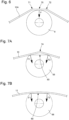
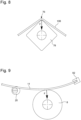
- FIG. 6 Various other advantageous variants are schematically shown in Figures 6, 7A and 7B .
- the variant of the Figure 6 is characterized by a brake spring 10A with a middle part having two bends 71 and 72 which are separated by a straight section 70 (without stress), which is supported, substantially in its middle, against the circular washer 8. This ensures at all times a "one-point" support of the brake spring 10A on the washer 8.
- the variants of the Figures 7A to 7B are characterized by an intermediate piece 68 which is not circular, but which is formed by a truncated washer having a straight zone 80.
- the brake spring 10 has, in its part median, an elbow 74 which is located opposite the right zone 80 of the truncated washer 68.
- the spring 11 is straight/rectilinear without constraint and, when it is put under tension to press against the intermediate piece, it bends a little (concave curvature seen from the intermediate piece) so that it presses at both ends of the straight zone 80 of this intermediate piece.
- the brake spring 10, respectively 11 exerts two forces F1 and F2 respectively at the two ends of the straight zone 80.
- the two forces F1 and F2 are globally radial, that is to say that their sum at a midpoint is radial.
- each of the two forces exerts a moment of force on the intermediate part 68, so that, if the spring moves longitudinally and one of the two forces F1 and F2 decreases relative to the other, the intermediate part 68 then automatically undergoes a small rotation so as to reestablish a balance of the two opposing moments of force which are exerted on it.
- the variant of the Figure 7B is preferable because the risk of rotation of the truncated washer is lower.
- this variant allows the desired braking torque to be maintained even if the brake spring undergoes a certain longitudinal displacement during an impact or sudden acceleration.
- the variant of the Figure 7A with a bent spring, is less likely to undergo longitudinal displacement in the event of an impact.
- the variant with a truncated washer is advantageous in preventing the intermediate piece from rotating during normal operation, which is important in ensuring a constant braking torque as set.
- the variants of the Figures 7A and 7B ensure at all times a “two-point” support in projection in the geometric plane of the spring.
- a particular variant is schematically represented in the Figure 8 .
- This variant like that of the Figure 6 , is designed to ensure at all times a pressure of the brake spring 10B at "one point" on the intermediate part 78 which has a generally square shape with rounded corners.
- the brake spring 10B has an elbow 76 such that the two straight parts of this spring on both sides of the elbow have between them a angle greater than 90° but relatively close to this value, for example an angle equal to 110°.
- One of the rounded corners of the intermediate piece is positioned in the bend 76 of the spring which exerts, when this spring and the intermediate piece 78 are stationary, a substantially radial force F on the intermediate piece.
- the braking device 6 comprises an eccentric 20 whose axis of rotation is perpendicular to the general plane 50, and therefore parallel to the central axis/axis of rotation 42 of the mobile 30, and which is arranged so as to press radially against the braking spring in order to be able to vary, by a rotation about its axis of rotation, said radial pressure force exerted by the braking spring on the intermediate part/washer.
- the eccentric 20 constitutes one of the two parts which maintain the braking spring under tension.
- the stress on this spring is varied, which makes it possible to adjust a braking torque applied to the first mobile 30 (chronograph mobile) when it is subjected to a rotational drive torque.
- This configuration is advantageous because it is not sensitive to vibrations and shocks.
- another device for adjusting the radial force is provided, in particular a device provided with a pressure member capable of being moved linearly.
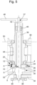
- FIG. 9 shows another embodiment of the invention in which the brake spring 11 is straight/rectilinear (without constraint).
- This spring is rigidly fixed at one of its two ends in a fixed part 82 and whose angular positioning in the geometric plane is not modifiable, thus avoiding any involuntary movement or movement due to an impact.
- the groove of the part 82 in which the end of the spring 11 is inserted is oriented so that a median zone of the spring exerts a radial pressure force F on the washer 8, this spring then having between the fixing part 82 and the point of support of the spring on the washer a first convex curvature (seen from the washer).
- an eccentric is provided which, in this embodiment, is located on the same side of the brake spring as the washer 8 which forms the intermediate part between the brake spring and the shaft of the mobile concerned.
- the brake spring 11 also has a second convex curvature between said support point and the eccentric 20, this second curvature being weaker than the first curvature because the radial force F is not zero.
- the variant shown in Figure 9 defines a construction of the single-point support type, i.e. with the brake spring resting at "one point" on the washer, according to the definition given above.
- a star-shaped intermediate piece is provided, for example with four to six points each having a slight rounding.
- the slightly convex brake spring presses at all times on two points of the star-shaped intermediate piece, thus exerting two forces forming, at their central point, an overall pressure force which is radial.
- the two forces generate two moments of force on the intermediate piece which are of the same intensity and opposite. It should also be noted that in the event of an impact, the braking device cannot be deregulated.
- FIGS 1 to 3 show the mechanical clock movement 2 with the braking device 6 previously mounted in a preliminary step occurring before the assembly of the first mobile 30.
- This assembly preliminary braking device 6 is advantageous. It is made possible in particular by the fact that the force exerted by the braking spring is radial and by the fact that the washer 8 is provided above a pinion and a wheel 32 forming the first mobile and, in the example shown where the first mobile is a chronograph mobile, a zero-reset heart 34.
- Figures 4 And 5 show the mechanical clock movement 2 after the first mobile 30 has been fitted into this movement and the braking device in a functional state.
- the washer 8 is arranged on a support 4 (barrel bridge) which has on the periphery of this washer a stop surface 26 located horizontally opposite the washer and diametrically opposite said support surface 25, so that the washer 8 and the braking spring 10 can be mounted beforehand in the mechanical watch movement 2, before the assembly of the first mobile 30, with the washer bearing against the stop surface 26, as shown in Figures 1 to 3 .
- the stop surface 26 is defined by a lateral surface of a cavity 12 machined in the support 4, the washer being arranged in this cavity 12 open on the lower side of the movement (by definition, the analog display is on the upper side).
- the stop surface 26 is arranged in such a way that, following the prior assembly of the washer 8 and the brake spring 10, the central cylindrical opening of the washer has at least one overlapping zone with the central circular opening of a barrel or tube 44, into which a part of the shaft 36 of the first wheel set 30 (chrono wheel set) is then introduced, such that the shaft can, when the first wheel set is assembled in the mechanical watch movement 2, penetrate into the two central circular openings without having to initially exert a radial force on the washer.
- the central cylindrical opening of the washer 8 is entirely superimposed on the central circular opening of the barrel 44.
- the shaft 36 of the first wheel set 30 is introduced into a barrel 44 which carries a display hand and which is thus rotatable, this barrel being pivoted in the plate 60 and the barrel bridge 4.
- a barrel 44 which carries a display hand and which is thus rotatable, this barrel being pivoted in the plate 60 and the barrel bridge 4.
- Inside the central opening of the barrel is arranged an internal bearing 46 in which is pivoted an end portion 37 of the shaft 36 on which the chronograph hand 48 is mounted, this end portion having a maximum diameter less than the diameter of the surface of revolution 35, in particular cylindrical and axial, which is finally located inside the central cylindrical opening 9 of the washer.
- the first mobile 30, forming in the embodiment shown a chronograph mobile, is pivoted by the upper bearing 46 and by a lower bearing 38 arranged in an opening of a bridge 40, and the washer 8 is no longer supported against the side wall 26 of the cavity 12 of the support 4, but supported by its central cylindrical opening against the shaft 36 of the first mobile, more precisely against a surface of revolution 35, advantageously cylindrical and axial, of this shaft.
- the barrel is pivoted between the barrel bridge 4, forming the support part of the washer 8, and the plate 60.
- the first mobile is rotated at times, on command, by a second mobile 52 via a clutch wheel 54 mounted on a lever 56, which is conventionally controlled by a column wheel or a cam (clutching shown schematically by an arrow at the Figure 4 ).
- the second mobile 52 comprises a drive wheel which is incorporated in the gear train of the barrel to the escape wheel 58. This drive wheel here forms a small seconds wheel of the time display of the watch receiving the mechanical watch movement 2.
- the present invention has been described in detail for a chronograph wheel set 30, but the braking device of the invention can be provided for other wheels of a mechanical watch movement, in particular for a small seconds wheel set when this wheel set is not included in the gear train from the barrel to the escape wheel 58.
- the braking device 6 comprises an eccentric 20 which makes it possible to easily adjust the radial pressure force exerted by the braking spring on the intermediate part/washer 8 and via the latter the radial force applied to the shaft 36 of the first mobile 30, and to adjust the friction force moment applied to this first mobile.
- the eccentric 20 makes it possible to adjust the braking torque once the braking device is fully mounted in the mechanical watch movement and without having to remove the braking spring in order to slightly modify its initial shape.
- the braking device 6 is such that it is protected against stresses which could damage it during the assembly of other parts of the mechanical watch movement, in particular during the assembly of the chrono mobile 30. During disassembly of the watch movement, and in particular of the first mobile 30, the braking device 6 can remain in place without its adjustment being modified.
- the braking device makes it possible to define the friction moment of force relatively precisely in advance, given that the lateral surface 9 of the intermediate part, in particular of the washer 8, has a height which is generally much greater than that of the brake spring, that the material of the intermediate part/washer 8 can be selected and that the diameter of the surface of revolution, defining a cylindrical and axial surface, of the shaft 36 against which the intermediate part/washer 8 bears is precisely determined.
Landscapes
- Physics & Mathematics (AREA)
- General Physics & Mathematics (AREA)
- Measurement Of Unknown Time Intervals (AREA)
- Braking Arrangements (AREA)
- Electric Clocks (AREA)
- Electromechanical Clocks (AREA)
Applications Claiming Priority (2)
| Application Number | Priority Date | Filing Date | Title |
|---|---|---|---|
| EP23172657 | 2023-05-10 | ||
| EP23174095 | 2023-05-17 |
Publications (2)
| Publication Number | Publication Date |
|---|---|
| EP4462193A1 true EP4462193A1 (de) | 2024-11-13 |
| EP4462193B1 EP4462193B1 (de) | 2026-01-14 |
Family
ID=90362247
Family Applications (1)
| Application Number | Title | Priority Date | Filing Date |
|---|---|---|---|
| EP24163635.6A Active EP4462193B1 (de) | 2023-05-10 | 2024-03-14 | Mechanisches uhrwerk, das ein bewegliches element umfasst, das ein anzeigeelement mit einer bremsvorrichtung umfasst |
Country Status (5)
| Country | Link |
|---|---|
| US (1) | US20240377788A1 (de) |
| EP (1) | EP4462193B1 (de) |
| JP (1) | JP7727784B2 (de) |
| KR (1) | KR20240163526A (de) |
| CN (1) | CN222994836U (de) |
Citations (4)
| Publication number | Priority date | Publication date | Assignee | Title |
|---|---|---|---|---|
| DE6800934U (de) | 1968-10-04 | 1969-09-25 | Junghans G M B H Fa Geb | Vorrichtung an einem uhrwerk zum bremsen einer getriebewelle |
| CH580301B5 (de) | 1973-07-10 | 1976-09-30 | Suisse Horlogerie | |
| EP2897003A2 (de) * | 2014-01-16 | 2015-07-22 | Richemont International S.A. | Uhrwerk und mechanische Uhr, die einen Chronografenmechanismus umfasst |
| WO2021121707A1 (fr) * | 2019-12-16 | 2021-06-24 | Eta Sa Manufacture Horlogère Suisse | Mecanisme d'affichage d'horlogerie |
Family Cites Families (7)
| Publication number | Priority date | Publication date | Assignee | Title |
|---|---|---|---|---|
| JP2006242793A (ja) * | 2005-03-04 | 2006-09-14 | Seiko Epson Corp | 時計 |
| EP2977829B1 (de) * | 2014-07-24 | 2017-07-12 | ETA SA Manufacture Horlogère Suisse | Anordnung mit beweglichem Bremselement einer Uhr |
| US20170351215A1 (en) * | 2015-01-05 | 2017-12-07 | Citizen Watch Co., Ltd. | Movement for mechanical timepiece |
| EP3396470B1 (de) * | 2017-04-24 | 2020-01-01 | ETA SA Manufacture Horlogère Suisse | Mechanische bremsvorrichtung für drehteil einer uhr |
| EP3667431B1 (de) * | 2018-12-13 | 2025-06-04 | Montres Breguet S.A. | Mobile anzeigeeinheit einer uhr mit reibungsregulierungsmechanismus |
| JP7467390B2 (ja) * | 2021-06-15 | 2024-04-15 | シチズン時計株式会社 | 指針のふらつき低減構造 |
| EP4160322B1 (de) * | 2021-09-29 | 2025-06-25 | ETA SA Manufacture Horlogère Suisse | Bremsfeder für trägerwelle einer anzeige, uhrwerk mit dieser bremsfeder und einbauverfahren dieser bremsfeder |
-
2024
- 2024-03-14 EP EP24163635.6A patent/EP4462193B1/de active Active
- 2024-04-11 JP JP2024063871A patent/JP7727784B2/ja active Active
- 2024-04-26 KR KR1020240056244A patent/KR20240163526A/ko active Pending
- 2024-05-07 US US18/656,771 patent/US20240377788A1/en active Pending
- 2024-05-10 CN CN202421009710.6U patent/CN222994836U/zh active Active
Patent Citations (4)
| Publication number | Priority date | Publication date | Assignee | Title |
|---|---|---|---|---|
| DE6800934U (de) | 1968-10-04 | 1969-09-25 | Junghans G M B H Fa Geb | Vorrichtung an einem uhrwerk zum bremsen einer getriebewelle |
| CH580301B5 (de) | 1973-07-10 | 1976-09-30 | Suisse Horlogerie | |
| EP2897003A2 (de) * | 2014-01-16 | 2015-07-22 | Richemont International S.A. | Uhrwerk und mechanische Uhr, die einen Chronografenmechanismus umfasst |
| WO2021121707A1 (fr) * | 2019-12-16 | 2021-06-24 | Eta Sa Manufacture Horlogère Suisse | Mecanisme d'affichage d'horlogerie |
Also Published As
| Publication number | Publication date |
|---|---|
| CN222994836U (zh) | 2025-06-17 |
| KR20240163526A (ko) | 2024-11-19 |
| JP7727784B2 (ja) | 2025-08-21 |
| EP4462193B1 (de) | 2026-01-14 |
| JP2024163021A (ja) | 2024-11-21 |
| US20240377788A1 (en) | 2024-11-14 |
Similar Documents
| Publication | Publication Date | Title |
|---|---|---|
| EP2410386B1 (de) | Unruh mit Trägheitsregulierung mit Einsatzteil | |
| CH708525B1 (fr) | Mécanisme de stabilisation du fonctionnement du balancier-spiral, mouvement horloger et montre mécanique. | |
| CH705605A2 (fr) | Dispositif de réglage de la longueur active d'un spiral. | |
| CH710108A2 (fr) | Mécanisme à force constante, mouvement et pièce d'horlogerie. | |
| EP3032353B1 (de) | Ausbaubarer Spiralklötzchenträger | |
| WO2021121707A1 (fr) | Mecanisme d'affichage d'horlogerie | |
| EP4462193B1 (de) | Mechanisches uhrwerk, das ein bewegliches element umfasst, das ein anzeigeelement mit einer bremsvorrichtung umfasst | |
| CH720774A2 (fr) | Mouvement horloger mécanique comprenant un mobile portant un organe d'affichage et muni d'un dispositif de freinage | |
| EP4625066A1 (de) | Elektromechanische uhrwerk, das ein bewegliches element umfasst, das ein anzeigeelement mit einer bremsvorrichtung umfasst | |
| EP3037893B1 (de) | Mikromechanische Komponente oder Uhr mit flexiblem Führungsdraht | |
| CH721682A2 (fr) | Mouvement horloger électromécanique comprenant un mobile portant un organe d'affichage et muni d'un dispositif de freinage | |
| EP3391154B1 (de) | Schwingsystem für eine uhr | |
| EP4428628B1 (de) | Vorrichtung zur autonomen einstellung der aktiven länge einer spiralfeder | |
| WO2013104941A1 (fr) | Piece d'horlogerie a remontage automatique | |
| EP1960846B1 (de) | Uhrwerk | |
| EP1960848B1 (de) | Hammer einer uhr | |
| CH720580A2 (fr) | Dispositif de réglage autonome de la longueur active d'un spiral | |
| CH716423B1 (fr) | Ensemble limiteur d'horlogerie pour une montre comportant au moins un tourbillon ou un carrousel. | |
| EP4428624B1 (de) | Vorrichtung zur autonomen einstellung der aktiven länge einer spiralfeder | |
| EP2515185A1 (de) | Motor mit konstantem Drehmoment | |
| EP1408381B1 (de) | Zentrifugalregler eines Schlagwerkes, insbesondere in einer Uhr | |
| EP4715483A1 (de) | Uhrvorrichtung mit einer unruh-spiralfeder und einer gangeinstellvorrichtung | |
| EP3428738B1 (de) | Antriebs- und positioniersystem, und raste für die umsetzung dieses systems | |
| CH721446A2 (fr) | Mouvement horloger comprenant un élément rigide mobile accouplé à un élément élastique et procédé d'accouplement de ces deux éléments | |
| CH720583A2 (fr) | Dispositif de réglage autonome de la longueur active d'un spiral |
Legal Events
| Date | Code | Title | Description |
|---|---|---|---|
| PUAI | Public reference made under article 153(3) epc to a published international application that has entered the european phase |
Free format text: ORIGINAL CODE: 0009012 |
|
| STAA | Information on the status of an ep patent application or granted ep patent |
Free format text: STATUS: THE APPLICATION HAS BEEN PUBLISHED |
|
| AK | Designated contracting states |
Kind code of ref document: A1 Designated state(s): AL AT BE BG CH CY CZ DE DK EE ES FI FR GB GR HR HU IE IS IT LI LT LU LV MC ME MK MT NL NO PL PT RO RS SE SI SK SM TR |
|
| P01 | Opt-out of the competence of the unified patent court (upc) registered |
Free format text: CASE NUMBER: APP_9349/2025 Effective date: 20250225 |
|
| STAA | Information on the status of an ep patent application or granted ep patent |
Free format text: STATUS: REQUEST FOR EXAMINATION WAS MADE |
|
| 17P | Request for examination filed |
Effective date: 20250513 |
|
| GRAP | Despatch of communication of intention to grant a patent |
Free format text: ORIGINAL CODE: EPIDOSNIGR1 |
|
| STAA | Information on the status of an ep patent application or granted ep patent |
Free format text: STATUS: GRANT OF PATENT IS INTENDED |
|
| RIC1 | Information provided on ipc code assigned before grant |
Ipc: G04B 35/00 20060101AFI20250902BHEP Ipc: G04F 7/08 20060101ALI20250902BHEP |
|
| INTG | Intention to grant announced |
Effective date: 20250916 |
|
| GRAS | Grant fee paid |
Free format text: ORIGINAL CODE: EPIDOSNIGR3 |
|
| GRAA | (expected) grant |
Free format text: ORIGINAL CODE: 0009210 |
|
| STAA | Information on the status of an ep patent application or granted ep patent |
Free format text: STATUS: THE PATENT HAS BEEN GRANTED |
|
| AK | Designated contracting states |
Kind code of ref document: B1 Designated state(s): AL AT BE BG CH CY CZ DE DK EE ES FI FR GB GR HR HU IE IS IT LI LT LU LV MC ME MK MT NL NO PL PT RO RS SE SI SK SM TR |
|
| REG | Reference to a national code |
Ref country code: CH Ref legal event code: F10 Free format text: ST27 STATUS EVENT CODE: U-0-0-F10-F00 (AS PROVIDED BY THE NATIONAL OFFICE) Effective date: 20260114 Ref country code: GB Ref legal event code: FG4D Free format text: NOT ENGLISH |
|
| REG | Reference to a national code |
Ref country code: DE Ref legal event code: R096 Ref document number: 602024001992 Country of ref document: DE |
|
| REG | Reference to a national code |
Ref country code: CH Ref legal event code: R17 Free format text: ST27 STATUS EVENT CODE: U-0-0-R10-R17 (AS PROVIDED BY THE NATIONAL OFFICE) Effective date: 20260202 |
|
| REG | Reference to a national code |
Ref country code: IE Ref legal event code: FG4D Free format text: LANGUAGE OF EP DOCUMENT: FRENCH |
|
| PGFP | Annual fee paid to national office [announced via postgrant information from national office to epo] |
Ref country code: DE Payment date: 20260219 Year of fee payment: 3 |
|
| PGFP | Annual fee paid to national office [announced via postgrant information from national office to epo] |
Ref country code: AT Payment date: 20260301 Year of fee payment: 3 |
|
| PGFP | Annual fee paid to national office [announced via postgrant information from national office to epo] |
Ref country code: FR Payment date: 20260219 Year of fee payment: 3 |