EP4464149A2 - Moissonneuse dotée d'un appareil de récolte et procédé de fonctionnement de la moissonneuse - Google Patents
Moissonneuse dotée d'un appareil de récolte et procédé de fonctionnement de la moissonneuse Download PDFInfo
- Publication number
- EP4464149A2 EP4464149A2 EP24202939.5A EP24202939A EP4464149A2 EP 4464149 A2 EP4464149 A2 EP 4464149A2 EP 24202939 A EP24202939 A EP 24202939A EP 4464149 A2 EP4464149 A2 EP 4464149A2
- Authority
- EP
- European Patent Office
- Prior art keywords
- mulching
- harvesting
- harvesting machine
- unit
- overload
- Prior art date
- Legal status (The legal status is an assumption and is not a legal conclusion. Google has not performed a legal analysis and makes no representation as to the accuracy of the status listed.)
- Granted
Links
Images


Classifications
-
- A—HUMAN NECESSITIES
- A01—AGRICULTURE; FORESTRY; ANIMAL HUSBANDRY; HUNTING; TRAPPING; FISHING
- A01D—HARVESTING; MOWING
- A01D34/00—Mowers; Mowing apparatus of harvesters
- A01D34/835—Mowers; Mowing apparatus of harvesters specially adapted for particular purposes
- A01D34/8355—Mowers; Mowing apparatus of harvesters specially adapted for particular purposes for cutting up or crushing remaining standing stalks, e.g. stubble
-
- A—HUMAN NECESSITIES
- A01—AGRICULTURE; FORESTRY; ANIMAL HUSBANDRY; HUNTING; TRAPPING; FISHING
- A01D—HARVESTING; MOWING
- A01D43/00—Mowers combined with apparatus performing additional operations while mowing
- A01D43/08—Mowers combined with apparatus performing additional operations while mowing with means for cutting up the mown crop, e.g. forage harvesters
- A01D43/081—Mowers combined with apparatus performing additional operations while mowing with means for cutting up the mown crop, e.g. forage harvesters specially adapted for ensilage of maize
-
- A—HUMAN NECESSITIES
- A01—AGRICULTURE; FORESTRY; ANIMAL HUSBANDRY; HUNTING; TRAPPING; FISHING
- A01D—HARVESTING; MOWING
- A01D45/00—Harvesting of standing crops
- A01D45/02—Harvesting of standing crops of maize, i.e. kernel harvesting
- A01D45/021—Cornheaders
Definitions
- mulching machines are often used to chop up the plant stems that remain in the soil. This chop-up promotes rotting.
- the chopped plant stems can also be mixed in more easily during subsequent soil cultivation. This can also prevent pest infestation, for example by corn borers.
- Such mulching devices are usually mounted on a harvesting device, in particular a harvesting attachment, and are arranged downstream of a cutting tool of the harvesting device intended for harvesting the crop in a crop flow direction. They are arranged close to the ground and therefore repeatedly come into contact with obstacles such as stones or uneven ground. By hitting Such obstacles not only place a strain on the mulching equipment's processing tool, but also on its drive train, in particular the transmission and/or clutches of the drive train, so that damage or at least wear may occur.
- the publication EP 3 881 665 A1 an overload protection device for a mulching device, which has a connecting element that attaches the processing tool to the mulching device. If an overload occurs, the connecting element is designed to break. Although this predetermined breaking point does not damage the components of the mulching device's drive train, the mulching device must be repaired in order to continue driving in the field. In addition, the tool and its drive train are loaded until the connecting element breaks, so that wear and tear still occurs on the tool and the drive train.
- the publication EP 3 391 724 B1 discloses a self-propelled harvester with a harvesting attachment on which a mulching device is arranged.
- the harvester has a speed sensor for detecting the forward speed. It is designed to move the mulching device into an inoperative position when the forward speed falls below a minimum forward speed or when the harvester is reversing. This means that the mulching device gets caught in the field soil less often.
- the publication DE 10 2021 114 960 A1 discloses a harvesting attachment for harvesting stem-like plants with a mulching device, which has a shaft that can be driven in rotation by a drive, wherein a control device is configured to control the forward speed of the header and/or the inclination of the shaft relative to the vertical to change the speed of the anti-drive.
- the object of the present invention is to provide a harvesting machine with a harvesting device on which a mulching unit is arranged, in which wear on the mulching unit, the drive train of the mulching unit and/or the harvesting device is reduced and/or a service life of the mulching unit, the drive train and/or the harvesting device is increased, and which is easy to handle for the driver, wherein the mulching unit can be produced and/or operated cost-effectively.
- the harvesting machine is characterized in that the sensor is provided for detecting a crop flow in the harvesting machine, and the control unit is designed to pivot the mulching unit into the raised position relative to the working position when the crop flow is reduced or absent.
- the mulching unit By detecting a decreasing or lacking crop flow, the mulching unit is only pivoted into the working position during field operation as long as crops are being harvested. If no crops are being harvested, the mulching unit is pivoted into the raised position relative to the working position, for example when the harvester is at a standstill or during turning maneuvers, particularly on headlands and/or when reversing. Since the mulching unit is pivoted from the working position into the raised position when the crop flow decreases or fails, unnecessary operation of the mulching unit is avoided, so that no overload can occur on the processing tool. It can also be provided that the processing tool is not operated when the mulching unit is in the raised position. This reduces the power requirement of the harvester.
- the extended service life also reduces the (maintenance) costs for the mulching unit, at least in the long term or even in the medium term.
- a crop flow sensor already present in the harvesting machine or harvesting device is particularly preferably used as a sensor for detecting the crop flow.
- the sensor is arranged on the input side of the harvesting device or harvesting machine in the direction of crop flow.
- the sensor is preferably arranged in the harvesting device. It can be designed, for example, as an NIR sensor (near infrared sensor) or as an optoelectric sensor.
- the sensor is also preferably arranged in a feed arrangement of the harvesting machine. In this embodiment, it can be provided, for example, for measuring a deflection of a feed roller.
- the sensor is also preferably arranged in a The device is arranged on the harvester's discharge chute. It is designed as an NIR sensor, for example.
- the harvesting device is a harvesting attachment for a harvesting machine, in particular a self-propelled one. As such, it is preferably arranged at the front of the harvesting machine.
- the mulching unit can also be used for other harvesting devices that can be attached to a tractor or attached to the rear, for example.
- a sensor is provided for detecting an overload acting on the processing tool, and the control unit is designed to pivot the mulching unit into a raised position relative to the working position when the overload is detected.
- the mulching unit's working tool can be lifted over the obstacle when it comes into contact with the obstacle, such as a stone or an uneven ground. This automatically lifts it out of the blockage area.
- the overload is eliminated very quickly and the harvesting device is only loaded for a very short time.
- the driver does not have to intervene, can focus his attention on the further harvesting process and is not stressed or distracted by observing the mulching unit.
- the processing tool If the processing tool has already penetrated the field soil, it is lifted out of it very quickly. This means that the processing tool only experiences wear for a very short time, so wear is low and the service life of the processing tool is long.
- the overload means that no maintenance work is required on the field, as the mulching unit can continue to operate after the overload has occurred.
- the sensor for detecting the overload is preferably designed as a speed sensor or a torque sensor, which is arranged on the mulching unit.
- the Overload can then be detected directly on the mulching unit, in particular on or near the processing tool. Due to the large number of speed sensors and torque sensors used in technical devices, such sensors are available very inexpensively and the detection of overload in the mulching unit can therefore be implemented very cost-effectively.
- the mulching unit comprises a gearbox that is connected on the input side to a drive train of the harvesting device and/or the harvesting machine, and that comprises a tool-side output for driving the processing tool, with the sensor being arranged in the gearbox.
- the sensor By arranging the sensor in the gearbox, the sensor is arranged close to the processing tool.
- a sensor that is already provided for detecting the drive speed of the gearbox or the mulching unit is used as the sensor. This means that there are no costs for an additional sensor.
- the harvesting machine preferably also has a read-only memory in which the threshold value is stored.
- the threshold value is adjustable, in particular by the driver of the harvesting machine or a technician, in particular on an operator console.
- the control unit can also be set up to detect obstacles and to store this data in the read-only memory. Preferably, at least the type of obstacle, in particular stone or uneven ground, and its position are detected.
- control unit is designed to raise the mulching unit when pivoting into the raised position to a height above the field ground that is determined depending on an amount of overload and/or an operationally relevant parameter, or to a preset height above the field ground.
- the preset height can be, for example, a height above the field ground determined from experience, or a height above the field ground that is determined depending on the harvesting height of the harvesting device.
- the height above the field ground can be determined, for example, by an angle of rotation of the mulching unit about its pivot axis. It is preferably detected by means of an angle of rotation sensor on a pivot bearing of the mulching unit on which it is mounted on the harvesting device.
- the preset height is preferably stored in the read-only memory and is also preferably adjustable by the driver of the harvesting machine or a mechanic, in particular on the operator console.
- control unit is preferably designed to pivot the mulching unit back from the raised position into the working position in a time-controlled and/or path-controlled manner.
- the mulching unit is held in the raised position for a predetermined time and/or a predetermined distance when the overload is detected. After the time has elapsed and/or after the distance has been covered, the control unit pivots the mulching unit back into the working position.
- a position sensor in particular a satellite-based one, can be used to detect the position of the overload and/or the distance covered.
- the harvesting device has an actuator that is designed to pivot the mulching unit from the working position to the raised position and back.
- the actuator can advantageously be designed as a single-acting cylinder. In this embodiment, it is inexpensive to obtain.
- the mulching unit can preferably be raised by the cylinder by applying pressure to it. By removing the pressure from the cylinder, the raised mulching unit in this embodiment can be lowered again. If there is no pressure in the cylinder, it is advantageously possible to guide the mulching unit to the ground by pivoting it freely on the pivot axis.
- the object is further achieved with a harvesting device for such a harvesting machine.
- the harvesting device has a cutting and/or conveying device for harvesting crops. It has at least one drive train for connecting at least one mulching unit, preferably several mulching units.
- the drive train is preferably connected to a main transmission of the harvesting device.
- the at least one mulching unit can be connected to the main transmission of the harvesting device in such a way that it receives power.
- the harvesting device also preferably has a frame to which the mulching unit can be attached, in particular a (cross) support.
- the at least one mulching unit is preferably arranged detachably on the harvesting device. This means that it can be retrofitted and/or removed from the harvesting device, for example for maintenance purposes.
- the problem is further solved with a mulching unit for such a harvesting device.
- the mulching unit has a processing tool for processing plant stems that remain in the field soil during harvesting. It also has a sensor that is designed to detect an overload on the processing tool.
- the sensor is preferably arranged in a gear box of the mulching unit. It can be designed, for example, as a speed sensor or a torque sensor.
- the transmission can preferably be connected to a drive train of the harvesting device in a way that receives power.
- the mulching unit also preferably has attachment means, in particular a bracket, with which it can be attached to a frame, in particular to a (cross) support of the frame, of the harvesting device.
- the attachment means, in particular the bracket can also be arranged on the frame of the harvesting device.
- the mulching unit preferably also has an actuator with which the mulching unit can be raised from a working position to a raised position in the event of an overload and/or a decreasing or lacking crop flow. It is preferred that the actuator extends between the attachment, in particular the console, and a mulcher frame of the mulching unit.
- the method can further provide that at least one rotational speed and/or at least one torque of a processing tool of a mulching unit of the harvesting machine is measured, and an overload occurring on the processing tool is detected, in particular by a threshold value comparison.
- An overload of the processing tool can occur if it penetrates the field soil or hits an obstacle such as a stone.
- the process lifts the mulching unit affected by the overload out of the field soil or over the obstacle causing the overload.
- the processing tool and its drive components are only loaded for a very short time. The resulting wear is therefore minimal.
- the process thus enables the overload to be reduced or eliminated very quickly by lifting the mulching unit.
- the service life of the processing tool and/or the mulching unit is therefore extended compared to conventional mulching units.
- the mulching unit By detecting the decreasing or missing crop flow, the mulching unit is only swiveled into the working position during field operation as long as crop is being harvested. As the mulching unit is swiveled from the working position into the raised position when the crop flow decreases or fails, unnecessary operation of the mulching unit is avoided. As in the Since obstacles occur more frequently on headlands and/or when reversing and/or the working tool can penetrate the ground, raising the mulching unit depending on the crop flow also leads to reduced wear and an increased service life of the working tool and/or the drive train.
- the harvesting machine preferably has at least two mulching units, wherein the occurrence of the overload is preferably furthermore detected when either a speed difference between a highest of the currently detected speeds of the mulching units and a lowest of the currently detected speeds of the mulching units falls below a threshold value, and/or a torque difference between a highest of the currently detected torques of the mulching units and a lowest of the currently detected torques of the mulching units exceeds a threshold value.
- a large number of other calculation methods for detecting the overload are also possible.
- the speeds and/or torques of all mulching units assigned to one another can be taken into account when detecting the overload.
- the mulching unit or units can be swiveled back in a time-controlled and/or distance-controlled manner.
- this mulching unit or the mulching units of the section in which it is arranged and/or the group to which it is assigned are pivoted from the working position into the raised position.
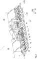
- Fig. 1 shows a rear side of a harvesting device 1 for harvesting crops in a perspective view.
- the harvesting device 1 is designed here as a harvesting attachment and is designed in the manner of a corn header.
- the terms harvesting device 1 and harvesting attachment are used synonymously.
- the harvesting attachment 1 can be attached in a manner known per se to the front of a harvesting machine (not shown), for example a forage harvester or a combine harvester, and is moved over a field floor (not shown).
- the harvesting machine has a lifting mechanism which is designed to adjust a height and/or an inclination of the harvesting attachment 1 relative to the field ground.
- the harvesting attachment 1 can also have one or more detection means, for example sensors, for detecting its height and/or inclination relative to the field ground.
- the lifting mechanism of the harvesting machine can be controlled based on the detected height and/or inclination.
- the harvesting header 1 comprises several sections 13, 14.
- a left section 13 (in the drawing plane) and a right section 14 (in the drawing plane) are arranged in a field position during field operation in which they are aligned approximately horizontally to the field ground.
- Fig.1 shows the harvesting attachment 1 in the field position intended for field operation.
- the harvesting attachment 1 can be transferred from the field position to a transport position (not shown).
- the left section 13 and the right section 14 are designed to be adjustable relative to one another and to a frame (not shown) of the harvesting attachment 1.
- the harvesting attachment 1 is guided in a direction of travel 91 over the field ground, wherein a cutting and/or conveying device 2 cuts stalk-like crops and conveys them to an intake arrangement (not shown) of the harvesting machine.
- the harvesting attachment 1 has at least one mulching unit 4, which is intended to chop the plant stems remaining in the field soil.
- the mulching unit 4 is arranged downstream of the cutting and/or conveying device 2 in a material flow direction 11.
- the mulching unit 4 processes the plant stems with a processing tool 41 (see. Fig. 2 (b) and (c) ) mechanically after the cutting and/or conveying device 2 has cut the crop, in particular close to the ground.
- the harvesting attachment 1 has a plurality of mulching units 4 which are evenly distributed over a width of the harvesting attachment 1 in a transverse direction 92 which extends transversely to the direction of travel 91.
- a drive train 3 is provided for each of the sections 13, 14, within which the mulching units 4 arranged on the respective section 13, 14 can be driven.
- the drive train 3 comprises a drive shaft 31 in the harvesting attachment 1. It also comprises a gear 7 for each of the mulching units 4.
- it comprises cardan shafts 72 with which the gears 7 of adjacent mulching units 4 are connected to one another in an articulated manner.
- dust and/or splash protection means are arranged around the cardan shafts 72, which are not shown in the left section 13 for clarity.
- the harvesting attachment 1 with the mulching units 4 is driven via a main transmission 8.
- the main transmission 8 has a PTO connection 81 with which it can be connected to the harvesting machine to receive power.
- On the output side it is connected to the two drive shafts 31 of the drive trains 3 for driving the mulching units 4.
- a drive train (not shown) for driving the cutting and/or conveying device 2.
- Further drive trains (not shown) can be provided for driving further components of the harvesting attachment 1.
- the harvesting attachment has sensors 6 (see also Fig. 3 ) which are provided for detecting an overload occurring on one of the mulching units 4.
- each of the gears 7 provided for driving one of the mulching units 4 has a sensor 6.
- the mulching units 4 rest on the field soil, in particular with their weight, while in the raised position S2 they are spaced apart from it. By raising, one mulching unit 4 or several mulching units 4 are guided at a height above the field soil. This allows uneven ground and/or obstacles to be overcome without overloading the harvesting attachment 1, the mulching units 4 and/or the drive train 3.
- Fig. 1 the mulching units 4 in the left section 13 are all shown in the working position S1, while in the right section 14 one of the mulching units 4 is shown in the raised position S2 relative to the others.
- the pivoting of the mulching unit 4 is explained below using the Fig. 2 explained in more detail.
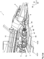
- Fig. 2 (a) shows a section of the right section 14 of the harvesting attachment 1 of the Fig. 1 in a perspective view.
- the mulching unit 4 is supported on the field soil by means of a skid 45.
- the mulching unit 4 rests on the field soil with its weight. It is then arranged in the working position S1.
- the mulching unit 4 is pivotally connected to the frame 12 of the harvesting attachment 1 about a pivot axis S. Pivoting the mulching unit 4 about the pivot axis S enables the mulching unit 4 to be lifted from the field ground.
- the pivot axis S extends in a transverse direction 92 transverse to the direction of travel 91. By lifting, the mulching unit 4 is spaced from the field ground in the raised position S2 in a vertical direction 93 that extends transverse to the transverse direction 92 and transverse to the direction of travel 91.
- the mulching unit 4 has the actuator 44 for lifting.
- the actuator 44 extends between the harvesting attachment 1 and the mulching unit 4. This is in Fig. 2 (c) described in more detail.
- the drive of the mulching unit 4, in particular of the processing tool 41 can be provided so that it can be switched off in the raised position S2, in particular automatically.
- the universal joint shaft 72 of the drive train 3 extends between the mulching unit 4 arranged in the raised position S2 and the adjacent mulching unit 4 arranged in the working position S1 at an angle (not designated) to the transverse direction 92.
- the gears 7 of these mulching units 4 are therefore arranged offset from one another in the vertical direction 93. This is possible in that the universal joint shafts 72 between the gears 7 of the mulching units 4 are each connected to gear shafts 76 of the gears 7 by means of cardan joints 78.
- the gears 7 are arranged in series (not designated) one behind the other and are connected to one another by the cardan shafts 72.
- the gears 7 are designed as T-gears and each have the gear shaft 76 (see Fig. 3 ) that passes through them.
- the gear shaft 76 of the first gear 7 in the row is connected to the drive shaft 31 of the front harvesting attachment 1 or to a spur gear (not designated) upstream of the gear 7.
- the gear shafts 76 of the downstream gears 7 are each connected on the drive side to the gear shaft 76 of the upstream gear 7 adjacent to them.
- the gear shafts 76 of the gears 7, with the exception of the last gear 7 in the row, are each intended to drive the adjacent, subsequent gear 7.
- the cardan shafts 72 are also linked to the gear shafts 76 of the subsequent gear 7 by means of universal joints 78. This linkage enables the spatial offset between the gears 7, so that the mulching units 4 can be raised relative to their adjacent mulching units 4.
- Fig. 2 (b) shows a section of the harvesting header 1 of the Fig. 2 (a) in a perspective view in which a bottom side (not marked) of the harvesting attachment 1 with several mulching units 4 is visible.
- the processing tools 41 of the mulching units 4 can be seen, each of which can be driven in rotation about a drive axis 42 by its gear 7.
- the drive axes 42 of the processing tools 41 are aligned transversely to the gear shaft 76 of the gear 7 (see also Fig. 3 ).
- the machining tool 41 is connected to a tool-side output 71 (see Fig. 3 ) of the gear 7 is fixed in a rotationally fixed manner, for example screwed, so that the impact body 43 can rotate about the drive axis 42.
- It has a blunt impact body 43, which is intended to work the plant stems in the field soil.
- a plurality of impact bodies 43 are arranged evenly distributed around the drive axis 42.
- an embodiment with two impact bodies 43 is shown.
- three or more impact bodies can also be used.
- 43 can be used.
- knives can also be provided instead of the impact bodies 43.
- the mulching unit 4 also has a mulching frame 48 and the cover 47.
- the cover 47 is arranged above the processing tool 41. It prevents processed plant stems or disturbed field soil from being thrown upwards by the rotating processing tool 41.
- the cover 47 can be designed as a sheet metal.
- the cover is attached to the mulching frame 48, which is formed in particular from webs and ribs.
- the gear 7 is arranged on the top of the mulching unit, on a side of the cover 47 facing away from the processing tool 41.
- the cover 47 extends in the material flow direction 11 to one end to which the skid 45 is attached.
- the skid 45 can be adjusted relative to the cover 47 and/or relative to the processing tool 41 by means of a hole pattern and/or an elongated hole.
- the skid 45 can also be designed to be adjustable by means of an adjustment actuator (not shown), wherein the adjustment actuator is articulated at one end to the mulcher frame 48 and/or the cover 47 of the mulching unit 4 and at another end to the skid 45.
- the cutting and/or conveying device 2 here comprises a plurality of cutting elements 22 and a plurality of conveying elements 23.
- the cutting elements 22 are designed as rotating cutting disks and are evenly distributed across the working width of the harvesting attachment 1.
- a knife bar or the like can also be used instead of these cutting elements 22 to cut the plant stems.
- a rotating endless conveyor (not marked) is used to convey the crop.
- Each section 13, 14 of the harvesting attachment 1 has at least one such endless conveyor.
- the conveyor elements 23 are arranged on the endless conveyor.
- Each of the conveyor elements 23 has a plurality of conveyor tines 24, which are provided for carrying along the crop cut by the cutting element 23.
- a cross conveyor in the form of a screw, rotating conveyor drums or the like can also be used as the conveyor element 23.
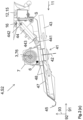
- Fig. 2(c) shows a side view of a sectional view of the mulching unit 4 arranged on the harvesting header 1.
- the linkage of the mulching unit 4 to the frame 12 of the harvesting header 1 can be seen.
- the frame 12 of the harvesting attachment 1 comprises a cross member 15 extending in the transverse direction 92, to which a bracket 16 is screwed.
- the bracket is therefore detachably attached to the cross member 15 and can be removed by unscrewing it.
- Other fastening means can also be provided with which the bracket is detachably attached to the frame 12 of the harvesting attachment 1, for example by locking or clamping, or permanently attached, for example by gluing, welding or riveting.
- the mulcher frame 48 is mounted on the bracket 16 so that it can pivot about the pivot axis S.
- the pivot axis S can, for example, extend along a pivot shaft (not designated) formed by a pin joint.
- the mulching unit 4 is suspended on the pivot axis S so that it can swing freely, is guided over the field soil by its weight and can therefore follow the contours of the field soil.
- the skid 45 is provided for support on the field soil.
- the actuator 44 for pivoting the mulching unit 4 extends between the harvesting attachment 1, here the bracket 16, and the mulcher frame 48. It is attached to the bracket 16 and to the mulcher frame 48, for example by means of a bolt 441, 442, in particular about the respective bolt axes (not designated), so as to be rotatable.
- the actuator 44 is a pneumatic and/or hydraulic cylinder and is designed in particular to be single-acting. By retracting a piston rod 443 of the actuator 44, the mulching unit 4 is raised relative to the field ground from the working position S1 to the raised position S2.
- the gear 7 is attached to an upper side (not designated) of the cover 47, in particular to the mulcher frame 48 and/or the cover 47. It is therefore raised together with the mulching unit 4 when it is pivoted about the pivot axis S.
- the gear shaft 76 of the gear 7 is visible.
- the gear 7 has an output 71 (see Fig. 3 ) which extends in the direction of the drive axis of the machining tool 41 and can be driven in rotation by the gear shaft 76.
- the machining tool 41 is attached to the output 71 in a rotationally fixed manner and is therefore driven about the drive axis 42 when the gear 1 is driven.
- the sensor 6 for detecting the overload is located in the gearbox 7. This is done as part of the Fig. 3 described.
- the overload occurs when the processing tool 41 hits an obstacle such as a stone or the field soil on the processing tool 41 of the mulching unit 4.
- the processing tool 41 is then braked or blocked.
- the torque acting on the processing tool increases and the speed decreases.
- the sensor 6 By designing the sensor 6 as a speed sensor 61 or as a torque sensor 62, such an impact on the obstacle and the resulting overload can therefore be measured.
- the sensor 6 sends a signal to the control unit 5, which causes the actuator 44 to pivot the mulching unit 4 from the working position S1 into the raised position S2. In the raised position S2, the processing tool 41 is lifted over the obstacle causing the overload and/or lifted out of the field soil.
- the control unit 5 is designed to raise the mulching unit 4 to a preset overload height.
- a height to which the mulching unit 4 is raised in the raised position S2 can also be set depending on an amount of overload.
- the control unit 5 is further configured to pivot the mulching unit 4 back from the raised position S2 to the working position S1 in a time-controlled and/or path-controlled manner.
- the time control and/or path control when pivoting the mulching unit 4 back from the raised position S2 to the working position S1 can be carried out with preset or pre-adjustable amounts for the time and/or the path, or depending on the amount of the overload.
- mulching units 4 can also be assigned to a group.
- the control unit 5 pivots all mulching units 4 of the group from the working position S1 into the raised position S2 when the overload on one of the mulching units 4 of the group is detected.
- the mulching units 4 of one of the sections 13, 14 of the front harvesting attachment 1 and/or those mulching units 4 that are connected to the same drive train 3 can be assigned to a group and pivoted together from the working position S1 into the raised position S2.
- Fig. 3 shows in (a) and (b) different embodiments of a transmission 7 for such a mulching unit 4.
- the gears 7 are each designed as T-gears. They each have a housing 77 through which the gear shaft 76 passes.
- the gear shafts have open ends 761, 762 opposite one another.
- the open ends 761, 762 can each be connected, in particular by means of the cardan joints 78 and universal joint shafts 72, on the drive side to the drive shaft 31 of the front harvesting attachment 1 or to the gear 7 of the mulching unit 4 arranged upstream of them, and on the output side to the gear 7 of the mulching unit 4 arranged downstream of them.
- Each of the gears 7 comprises a bevel gear pair 74, 75 with a first bevel gear 74 that completely surrounds the gear shaft 76 and a second bevel gear 75 that forms a tool-side output 71.
- the two bevel gears 74, 75 each have a toothing (not designated) that mesh with one another, so that the second bevel gear 75 is driven when the first bevel gear 74 is driven.
- the machining tool 41 is mounted on the tool-side output 71, in particular at a fastening point 49. As a result, the machining tool 41 is also driven when the first bevel gear 74 is driven.
- the drive shaft 42 (see Fig. 2 (c) ) of the machining tool 41 is aligned transversely to the gear shaft 76.
- the transmission 7 has an overload clutch 73, which is designed here as a ratchet clutch, for example.
- the overload clutch 73 is intended to drive-disconnect the drive train 3 from the tool-side output 71 of the mulching unit 4 when an overload occurs on the mulching unit 4.
- it has engagement means (not shown) which, in an engaged state (not designated) of the overload clutch 73, are spring-loaded into engagement with counter-engagement means (not shown) of the transmission shaft 76, in particular with recesses in the transmission shaft 76, and which, when an engagement force is exceeded, come out of engagement with the counter-engagement means, so that the overload clutch 73 is uncoupled from the transmission shaft 76.
- the overload clutch 73 then slips on the transmission shaft 76.
- the first bevel gear 74 is mounted on the overload clutch 73 in a rotationally fixed manner.
- the overload clutch 73 When the overload clutch 73 is engaged, it rotates with the gear shaft 76.
- the overload occurs on the machining tool 41, it is braked or even blocked, so that the second bevel gear 75 is braked. This also brakes the first bevel gear 74.
- the overload clutch 73 slips, so that the machining tool 41 is driven by the gear shaft 76, and thus the drive train 3 is separated. This protects the drive train 3 from damage if the machining tool 41 is overloaded.
- the sensor 6 is designed as a speed sensor 61.
- the speed sensor 61 is attached in the housing 77 and detects a speed of the first bevel gear 74. Since the two bevel gears 74, 75 are in mesh with each other, the speed of the tool-side output 71 is also detected. The occurrence of the overload is detected when the speed of the tool-side output 71 falls below a threshold value.
- the occurrence of the overload can alternatively be detected if a speed difference between a highest of the currently detected speeds of the mulching units 4 of the group and a lowest of the currently detected speeds of the mulching units 4 of the group falls below a threshold value.
- the speed sensor 61 or the speed sensors 61 send their measured value to the control unit 5, which carries out the threshold value comparison and, if an overload is detected, pivots the mulching unit 4 or the mulching units 4 of the group from the working position S1 to the raised position S2.
- Fig. 3 (b) shows an embodiment of the transmission 7, in which the sensor 6 for detecting the overload is designed as a torque sensor 62.
- the torque sensor 62 is designed here in the form of a torque measuring hub 62. Therefore, the terms torque sensor 62 and torque measuring hub 62 are used synonymously below.
- the two bevel gears 74, 75 each have a toothing (not designated) that mesh with each other, so that the second bevel gear 75 is driven when the first bevel gear 74 is driven.
- no overload clutch 73 is visible here.
- the gear 7 preferably has the overload clutch 73 here too in order to separate the tool-side output 71 from the drive train 3.
- the overload clutch can, for example, be integrated into the torque measuring hub 62.
- the torque sensor 62 detects the torque applied to the first bevel gear 74. Since the first and second bevel gears 74, 75 are in engagement with one another, the torque applied to the machining tool 41 is thereby detected. The occurrence of the overload is detected by a threshold value comparison, namely when the torque exceeds a threshold value.
- the overload can also be detected alternatively in the case of grouped mulching units 4 if a torque difference between a highest of the currently detected torques of the mulching units 4 of the group and a lowest of the currently detected torques of the mulching units 4 of the group exceeds a threshold value.
- the torque sensor 61 or the torque sensors 61 send their measured value to the control unit 5, which carries out the threshold value comparison and, if an overload is detected, pivots the mulching unit 4 or the mulching units 4 of the group from the working position S1 to the raised position S2.
- the currently recorded measured values, in particular speed or torque, of the sensor 6 and/or the occurrence of the overload can be displayed to the operator on an operator console, for example in a driver's cab of the harvesting machine 1. If the overload occurs, an acoustic signal can be issued to the driver alternatively or additionally.
- navigation data in particular from a GPS receiver (not shown) of the harvesting machine 1, can be stored in order to be able to subsequently process the field soil in a targeted manner.
Landscapes
- Life Sciences & Earth Sciences (AREA)
- Environmental Sciences (AREA)
- Harvester Elements (AREA)
- Harvesting Machines For Root Crops (AREA)
Applications Claiming Priority (2)
| Application Number | Priority Date | Filing Date | Title |
|---|---|---|---|
| DE102022125382.1A DE102022125382A1 (de) | 2022-09-30 | 2022-09-30 | Erntemaschine mit einem Erntegerät und Verfahren zum Betreiben der Erntemaschine |
| EP23196004.8A EP4344529B1 (fr) | 2022-09-30 | 2023-09-07 | Récolteuse dotée d'un appareil de récolte et procédé de fonctionnement de la récolteuse |
Related Parent Applications (2)
| Application Number | Title | Priority Date | Filing Date |
|---|---|---|---|
| EP23196004.8A Division-Into EP4344529B1 (fr) | 2022-09-30 | 2023-09-07 | Récolteuse dotée d'un appareil de récolte et procédé de fonctionnement de la récolteuse |
| EP23196004.8A Division EP4344529B1 (fr) | 2022-09-30 | 2023-09-07 | Récolteuse dotée d'un appareil de récolte et procédé de fonctionnement de la récolteuse |
Publications (3)
| Publication Number | Publication Date |
|---|---|
| EP4464149A2 true EP4464149A2 (fr) | 2024-11-20 |
| EP4464149A3 EP4464149A3 (fr) | 2025-02-26 |
| EP4464149B1 EP4464149B1 (fr) | 2025-10-29 |
Family
ID=87971831
Family Applications (2)
| Application Number | Title | Priority Date | Filing Date |
|---|---|---|---|
| EP24202939.5A Active EP4464149B1 (fr) | 2022-09-30 | 2023-09-07 | Moissonneuse dotée d'un appareil de récolte et procédé de fonctionnement de la moissonneuse |
| EP23196004.8A Active EP4344529B1 (fr) | 2022-09-30 | 2023-09-07 | Récolteuse dotée d'un appareil de récolte et procédé de fonctionnement de la récolteuse |
Family Applications After (1)
| Application Number | Title | Priority Date | Filing Date |
|---|---|---|---|
| EP23196004.8A Active EP4344529B1 (fr) | 2022-09-30 | 2023-09-07 | Récolteuse dotée d'un appareil de récolte et procédé de fonctionnement de la récolteuse |
Country Status (5)
| Country | Link |
|---|---|
| EP (2) | EP4464149B1 (fr) |
| DE (1) | DE102022125382A1 (fr) |
| DK (2) | DK4464149T3 (fr) |
| HU (1) | HUE071348T2 (fr) |
| PL (2) | PL4344529T3 (fr) |
Citations (3)
| Publication number | Priority date | Publication date | Assignee | Title |
|---|---|---|---|---|
| EP3391724B1 (fr) | 2017-04-19 | 2020-01-29 | Deere & Company | Appareil de paillage destiné au traitement de souches debout dans un champ ayant une position et/ou force d'appui au sol réglable |
| EP3881665A1 (fr) | 2020-03-18 | 2021-09-22 | Deere & Company | Appareil de paillage destiné au traitement des chaumes végétaux |
| DE102021114960A1 (de) | 2020-06-30 | 2021-12-30 | Deere & Company | Erntevorsatz zur Ernte stängelartiger Pflanzen mit drehzahlveränderlich angetriebenem Mulchgerät |
Family Cites Families (2)
| Publication number | Priority date | Publication date | Assignee | Title |
|---|---|---|---|---|
| EP3272199B1 (fr) * | 2016-07-20 | 2019-09-25 | Deere & Company | Broyeur destiné au traitement de résidus de cultures dans un champ |
| DE102021120012A1 (de) * | 2020-08-25 | 2022-03-03 | Deere & Company | Anordnung zur Steuerung der Höhe eines Erntevorsatzes zur Ernte stängelartigen Ernteguts |
-
2022
- 2022-09-30 DE DE102022125382.1A patent/DE102022125382A1/de active Pending
-
2023
- 2023-09-07 PL PL23196004.8T patent/PL4344529T3/pl unknown
- 2023-09-07 DK DK24202939.5T patent/DK4464149T3/da active
- 2023-09-07 HU HUE23196004A patent/HUE071348T2/hu unknown
- 2023-09-07 EP EP24202939.5A patent/EP4464149B1/fr active Active
- 2023-09-07 EP EP23196004.8A patent/EP4344529B1/fr active Active
- 2023-09-07 PL PL24202939.5T patent/PL4464149T3/pl unknown
- 2023-09-07 DK DK23196004.8T patent/DK4344529T3/da active
Patent Citations (3)
| Publication number | Priority date | Publication date | Assignee | Title |
|---|---|---|---|---|
| EP3391724B1 (fr) | 2017-04-19 | 2020-01-29 | Deere & Company | Appareil de paillage destiné au traitement de souches debout dans un champ ayant une position et/ou force d'appui au sol réglable |
| EP3881665A1 (fr) | 2020-03-18 | 2021-09-22 | Deere & Company | Appareil de paillage destiné au traitement des chaumes végétaux |
| DE102021114960A1 (de) | 2020-06-30 | 2021-12-30 | Deere & Company | Erntevorsatz zur Ernte stängelartiger Pflanzen mit drehzahlveränderlich angetriebenem Mulchgerät |
Also Published As
| Publication number | Publication date |
|---|---|
| PL4344529T3 (pl) | 2025-06-23 |
| DK4344529T3 (da) | 2025-05-19 |
| EP4344529A1 (fr) | 2024-04-03 |
| EP4344529B1 (fr) | 2025-02-19 |
| DE102022125382A1 (de) | 2024-04-04 |
| DK4464149T3 (da) | 2025-12-22 |
| HUE071348T2 (hu) | 2025-08-28 |
| PL4464149T3 (pl) | 2026-02-23 |
| EP4464149A3 (fr) | 2025-02-26 |
| EP4464149B1 (fr) | 2025-10-29 |
Similar Documents
| Publication | Publication Date | Title |
|---|---|---|
| EP3272199B1 (fr) | Broyeur destiné au traitement de résidus de cultures dans un champ | |
| EP3622798B1 (fr) | Dispositif de commande de la hauteur et / ou de l'inclinaison d'une tête de récolte destinée à la récolte des produits de récolte en forme de tige | |
| EP3391724B1 (fr) | Appareil de paillage destiné au traitement de souches debout dans un champ ayant une position et/ou force d'appui au sol réglable | |
| DE102017222587B4 (de) | Mulchgerät zur Bearbeitung von auf einem Feld stehenden Pflanzenstümpfen mit verstellbarer Position und/oder Bodenandruckkraft | |
| EP1927277B1 (fr) | Moissonneuse agricole dotée d'une goulotte de transfert | |
| EP3269223B1 (fr) | Tête de récolte comprenant un dispositif de paillage | |
| DE102007009587A1 (de) | Vorrichtung zur Einstellung der Position des Nachbeschleunigungsorgans in einer landwirtschaftlichen Erntemaschine | |
| EP1932416A1 (fr) | Dispositif muni d'une première et d'une seconde unité de travail | |
| WO2015000768A1 (fr) | Appareil agricole et procédé de traitement de chaumes végétaux | |
| DE102005025319B4 (de) | Zusatzschneideinrichtung zur Verwendung an einem Hochschnittmodus betriebenen Mähdrescher | |
| DE102016212621A1 (de) | Erntevorsatz mit einer Mulcheinrichtung | |
| EP1566092B1 (fr) | Dispositif de récolte avec broyeur | |
| EP3881665B1 (fr) | Appareil de paillage destiné au traitement des chaumes végétaux | |
| EP4344529B1 (fr) | Récolteuse dotée d'un appareil de récolte et procédé de fonctionnement de la récolteuse | |
| DE102016214323A1 (de) | Mulcheinrichtung zur mechanischen Bearbeitung von Pflanzenstoppeln | |
| DE102016214324A1 (de) | Erntevorsatz mit einem Mulchgerät zur Bearbeitung von auf einem Feld stehenden Pflanzenstümpfen | |
| EP3603376A1 (fr) | Machine de récolte doté d'une tête de récolte et d'une roue d'appui | |
| BE1027694B1 (de) | Antriebsanordnung für ein landwirtschaftliches Arbeitsgerät mit mechanischer Überlastkupplung und selbsttätiger Anpassung des Abschaltmoments | |
| BE1027108B1 (de) | Erntevorsatz mit einem Mulchgerät | |
| EP1932415B1 (fr) | Dispositif muni d'une première et d'une seconde unité de travail | |
| DE102019216223A1 (de) | Mulchgerät zur Bearbeitung von auf einem Feld stehenden Pflanzenstoppeln mit Pendelwinkelbegrenzung | |
| EP1566091B1 (fr) | Dispositif de récolte avec un hacheur pour tiges | |
| EP3598883B1 (fr) | Dispositif outil pour le montage sur une machine agricole, machine agricole ainsi que procédé de fonctionnement d'une telle machine agricole | |
| DE202006019070U1 (de) | Vorrichtung mit einer ersten und einer zweiten Arbeitseinheit | |
| DE102016214321A1 (de) | Erntevorsatz zur Ernte stängelartiger Pflanzen mit einem Werkzeug zur Bearbeitung von Pflanzenstoppeln |
Legal Events
| Date | Code | Title | Description |
|---|---|---|---|
| PUAI | Public reference made under article 153(3) epc to a published international application that has entered the european phase |
Free format text: ORIGINAL CODE: 0009012 |
|
| STAA | Information on the status of an ep patent application or granted ep patent |
Free format text: STATUS: REQUEST FOR EXAMINATION WAS MADE |
|
| 17P | Request for examination filed |
Effective date: 20240926 |
|
| AC | Divisional application: reference to earlier application |
Ref document number: 4344529 Country of ref document: EP Kind code of ref document: P |
|
| AK | Designated contracting states |
Kind code of ref document: A2 Designated state(s): AL AT BE BG CH CY CZ DE DK EE ES FI FR GB GR HR HU IE IS IT LI LT LU LV MC ME MK MT NL NO PL PT RO RS SE SI SK SM TR |
|
| P01 | Opt-out of the competence of the unified patent court (upc) registered |
Free format text: CASE NUMBER: APP_64190/2024 Effective date: 20241204 |
|
| REG | Reference to a national code |
Ref country code: DE Ref legal event code: R079 Free format text: PREVIOUS MAIN CLASS: A01D0045020000 Ipc: A01D0034835000 Ref document number: 502023002112 Country of ref document: DE |
|
| PUAL | Search report despatched |
Free format text: ORIGINAL CODE: 0009013 |
|
| AK | Designated contracting states |
Kind code of ref document: A3 Designated state(s): AL AT BE BG CH CY CZ DE DK EE ES FI FR GB GR HR HU IE IS IT LI LT LU LV MC ME MK MT NL NO PL PT RO RS SE SI SK SM TR |
|
| RIC1 | Information provided on ipc code assigned before grant |
Ipc: A01D 45/02 20060101ALI20250117BHEP Ipc: A01D 43/08 20060101ALI20250117BHEP Ipc: A01D 34/835 20060101AFI20250117BHEP |
|
| RIC1 | Information provided on ipc code assigned before grant |
Ipc: A01D 45/02 20060101ALI20250428BHEP Ipc: A01D 43/08 20060101ALI20250428BHEP Ipc: A01D 34/835 20060101AFI20250428BHEP |
|
| GRAP | Despatch of communication of intention to grant a patent |
Free format text: ORIGINAL CODE: EPIDOSNIGR1 |
|
| STAA | Information on the status of an ep patent application or granted ep patent |
Free format text: STATUS: GRANT OF PATENT IS INTENDED |
|
| INTG | Intention to grant announced |
Effective date: 20250611 |
|
| GRAS | Grant fee paid |
Free format text: ORIGINAL CODE: EPIDOSNIGR3 |
|
| GRAA | (expected) grant |
Free format text: ORIGINAL CODE: 0009210 |
|
| STAA | Information on the status of an ep patent application or granted ep patent |
Free format text: STATUS: THE PATENT HAS BEEN GRANTED |
|
| AC | Divisional application: reference to earlier application |
Ref document number: 4344529 Country of ref document: EP Kind code of ref document: P |
|
| AK | Designated contracting states |
Kind code of ref document: B1 Designated state(s): AL AT BE BG CH CY CZ DE DK EE ES FI FR GB GR HR HU IE IS IT LI LT LU LV MC ME MK MT NL NO PL PT RO RS SE SI SK SM TR |
|
| REG | Reference to a national code |
Ref country code: CH Ref legal event code: F10 Free format text: ST27 STATUS EVENT CODE: U-0-0-F10-F00 (AS PROVIDED BY THE NATIONAL OFFICE) Effective date: 20251029 Ref country code: GB Ref legal event code: FG4D Free format text: NOT ENGLISH |
|
| REG | Reference to a national code |
Ref country code: DE Ref legal event code: R096 Ref document number: 502023002112 Country of ref document: DE |
|
| REG | Reference to a national code |
Ref country code: IE Ref legal event code: FG4D Free format text: LANGUAGE OF EP DOCUMENT: GERMAN |
|
| REG | Reference to a national code |
Ref country code: CH Ref legal event code: R17 Free format text: ST27 STATUS EVENT CODE: U-0-0-R10-R17 (AS PROVIDED BY THE NATIONAL OFFICE) Effective date: 20251128 |
|
| REG | Reference to a national code |
Ref country code: DK Ref legal event code: T3 Effective date: 20251219 |
|
| REG | Reference to a national code |
Ref country code: NL Ref legal event code: FP |
|
| PG25 | Lapsed in a contracting state [announced via postgrant information from national office to epo] |
Ref country code: ES Free format text: LAPSE BECAUSE OF FAILURE TO SUBMIT A TRANSLATION OF THE DESCRIPTION OR TO PAY THE FEE WITHIN THE PRESCRIBED TIME-LIMIT Effective date: 20251029 |
|
| REG | Reference to a national code |
Ref country code: LT Ref legal event code: MG9D |
|
| PG25 | Lapsed in a contracting state [announced via postgrant information from national office to epo] |
Ref country code: NO Free format text: LAPSE BECAUSE OF FAILURE TO SUBMIT A TRANSLATION OF THE DESCRIPTION OR TO PAY THE FEE WITHIN THE PRESCRIBED TIME-LIMIT Effective date: 20260129 |
|
| PG25 | Lapsed in a contracting state [announced via postgrant information from national office to epo] |
Ref country code: FI Free format text: LAPSE BECAUSE OF FAILURE TO SUBMIT A TRANSLATION OF THE DESCRIPTION OR TO PAY THE FEE WITHIN THE PRESCRIBED TIME-LIMIT Effective date: 20251029 Ref country code: HR Free format text: LAPSE BECAUSE OF FAILURE TO SUBMIT A TRANSLATION OF THE DESCRIPTION OR TO PAY THE FEE WITHIN THE PRESCRIBED TIME-LIMIT Effective date: 20251029 |
|
| PG25 | Lapsed in a contracting state [announced via postgrant information from national office to epo] |
Ref country code: RS Free format text: LAPSE BECAUSE OF FAILURE TO SUBMIT A TRANSLATION OF THE DESCRIPTION OR TO PAY THE FEE WITHIN THE PRESCRIBED TIME-LIMIT Effective date: 20260129 |
|
| PG25 | Lapsed in a contracting state [announced via postgrant information from national office to epo] |
Ref country code: IS Free format text: LAPSE BECAUSE OF FAILURE TO SUBMIT A TRANSLATION OF THE DESCRIPTION OR TO PAY THE FEE WITHIN THE PRESCRIBED TIME-LIMIT Effective date: 20260228 |
|
| PG25 | Lapsed in a contracting state [announced via postgrant information from national office to epo] |
Ref country code: PT Free format text: LAPSE BECAUSE OF FAILURE TO SUBMIT A TRANSLATION OF THE DESCRIPTION OR TO PAY THE FEE WITHIN THE PRESCRIBED TIME-LIMIT Effective date: 20260302 |
|
| PG25 | Lapsed in a contracting state [announced via postgrant information from national office to epo] |
Ref country code: LV Free format text: LAPSE BECAUSE OF FAILURE TO SUBMIT A TRANSLATION OF THE DESCRIPTION OR TO PAY THE FEE WITHIN THE PRESCRIBED TIME-LIMIT Effective date: 20251029 |