EP4464344A2 - Collecte, édition génomique et lavage de lymphocytes t - Google Patents
Collecte, édition génomique et lavage de lymphocytes t Download PDFInfo
- Publication number
- EP4464344A2 EP4464344A2 EP24202574.0A EP24202574A EP4464344A2 EP 4464344 A2 EP4464344 A2 EP 4464344A2 EP 24202574 A EP24202574 A EP 24202574A EP 4464344 A2 EP4464344 A2 EP 4464344A2
- Authority
- EP
- European Patent Office
- Prior art keywords
- blood
- mononuclear cell
- cell product
- product
- mnc
- Prior art date
- Legal status (The legal status is an assumption and is not a legal conclusion. Google has not performed a legal analysis and makes no representation as to the accuracy of the status listed.)
- Pending
Links
Images









Classifications
-
- A—HUMAN NECESSITIES
- A61—MEDICAL OR VETERINARY SCIENCE; HYGIENE
- A61M—DEVICES FOR INTRODUCING MEDIA INTO, OR ONTO, THE BODY; DEVICES FOR TRANSDUCING BODY MEDIA OR FOR TAKING MEDIA FROM THE BODY; DEVICES FOR PRODUCING OR ENDING SLEEP OR STUPOR
- A61M1/00—Suction or pumping devices for medical purposes; Devices for carrying-off, for treatment of, or for carrying-over, body-liquids; Drainage systems
- A61M1/02—Blood transfusion apparatus
- A61M1/0209—Multiple bag systems for separating or storing blood components
- A61M1/0218—Multiple bag systems for separating or storing blood components with filters
-
- A—HUMAN NECESSITIES
- A61—MEDICAL OR VETERINARY SCIENCE; HYGIENE
- A61M—DEVICES FOR INTRODUCING MEDIA INTO, OR ONTO, THE BODY; DEVICES FOR TRANSDUCING BODY MEDIA OR FOR TAKING MEDIA FROM THE BODY; DEVICES FOR PRODUCING OR ENDING SLEEP OR STUPOR
- A61M1/00—Suction or pumping devices for medical purposes; Devices for carrying-off, for treatment of, or for carrying-over, body-liquids; Drainage systems
- A61M1/02—Blood transfusion apparatus
- A61M1/0209—Multiple bag systems for separating or storing blood components
- A61M1/0231—Multiple bag systems for separating or storing blood components with gas separating means, e.g. air outlet through microporous membrane or gas bag
-
- A—HUMAN NECESSITIES
- A61—MEDICAL OR VETERINARY SCIENCE; HYGIENE
- A61M—DEVICES FOR INTRODUCING MEDIA INTO, OR ONTO, THE BODY; DEVICES FOR TRANSDUCING BODY MEDIA OR FOR TAKING MEDIA FROM THE BODY; DEVICES FOR PRODUCING OR ENDING SLEEP OR STUPOR
- A61M1/00—Suction or pumping devices for medical purposes; Devices for carrying-off, for treatment of, or for carrying-over, body-liquids; Drainage systems
- A61M1/02—Blood transfusion apparatus
- A61M1/0281—Apparatus for treatment of blood or blood constituents prior to transfusion, e.g. washing, filtering or thawing
-
- A—HUMAN NECESSITIES
- A61—MEDICAL OR VETERINARY SCIENCE; HYGIENE
- A61M—DEVICES FOR INTRODUCING MEDIA INTO, OR ONTO, THE BODY; DEVICES FOR TRANSDUCING BODY MEDIA OR FOR TAKING MEDIA FROM THE BODY; DEVICES FOR PRODUCING OR ENDING SLEEP OR STUPOR
- A61M1/00—Suction or pumping devices for medical purposes; Devices for carrying-off, for treatment of, or for carrying-over, body-liquids; Drainage systems
- A61M1/14—Dialysis systems; Artificial kidneys; Blood oxygenators ; Reciprocating systems for treatment of body fluids, e.g. single needle systems for hemofiltration or pheresis
- A61M1/16—Dialysis systems; Artificial kidneys; Blood oxygenators ; Reciprocating systems for treatment of body fluids, e.g. single needle systems for hemofiltration or pheresis with membranes
- A61M1/26—Dialysis systems; Artificial kidneys; Blood oxygenators ; Reciprocating systems for treatment of body fluids, e.g. single needle systems for hemofiltration or pheresis with membranes and internal elements which are moving
- A61M1/262—Dialysis systems; Artificial kidneys; Blood oxygenators ; Reciprocating systems for treatment of body fluids, e.g. single needle systems for hemofiltration or pheresis with membranes and internal elements which are moving rotating
- A61M1/265—Dialysis systems; Artificial kidneys; Blood oxygenators ; Reciprocating systems for treatment of body fluids, e.g. single needle systems for hemofiltration or pheresis with membranes and internal elements which are moving rotating inducing Taylor vortices
-
- A—HUMAN NECESSITIES
- A61—MEDICAL OR VETERINARY SCIENCE; HYGIENE
- A61M—DEVICES FOR INTRODUCING MEDIA INTO, OR ONTO, THE BODY; DEVICES FOR TRANSDUCING BODY MEDIA OR FOR TAKING MEDIA FROM THE BODY; DEVICES FOR PRODUCING OR ENDING SLEEP OR STUPOR
- A61M1/00—Suction or pumping devices for medical purposes; Devices for carrying-off, for treatment of, or for carrying-over, body-liquids; Drainage systems
- A61M1/36—Other treatment of blood in a by-pass of the natural circulatory system, e.g. temperature adaptation, irradiation ; Extra-corporeal blood circuits
- A61M1/3621—Extra-corporeal blood circuits
- A61M1/3622—Extra-corporeal blood circuits with a cassette forming partially or totally the blood circuit
- A61M1/36222—Details related to the interface between cassette and machine
- A61M1/362227—Details related to the interface between cassette and machine the interface providing means for actuating on functional elements of the cassette, e.g. plungers
-
- A—HUMAN NECESSITIES
- A61—MEDICAL OR VETERINARY SCIENCE; HYGIENE
- A61M—DEVICES FOR INTRODUCING MEDIA INTO, OR ONTO, THE BODY; DEVICES FOR TRANSDUCING BODY MEDIA OR FOR TAKING MEDIA FROM THE BODY; DEVICES FOR PRODUCING OR ENDING SLEEP OR STUPOR
- A61M1/00—Suction or pumping devices for medical purposes; Devices for carrying-off, for treatment of, or for carrying-over, body-liquids; Drainage systems
- A61M1/36—Other treatment of blood in a by-pass of the natural circulatory system, e.g. temperature adaptation, irradiation ; Extra-corporeal blood circuits
- A61M1/3621—Extra-corporeal blood circuits
- A61M1/3622—Extra-corporeal blood circuits with a cassette forming partially or totally the blood circuit
- A61M1/36224—Extra-corporeal blood circuits with a cassette forming partially or totally the blood circuit with sensing means or components thereof
-
- A—HUMAN NECESSITIES
- A61—MEDICAL OR VETERINARY SCIENCE; HYGIENE
- A61M—DEVICES FOR INTRODUCING MEDIA INTO, OR ONTO, THE BODY; DEVICES FOR TRANSDUCING BODY MEDIA OR FOR TAKING MEDIA FROM THE BODY; DEVICES FOR PRODUCING OR ENDING SLEEP OR STUPOR
- A61M1/00—Suction or pumping devices for medical purposes; Devices for carrying-off, for treatment of, or for carrying-over, body-liquids; Drainage systems
- A61M1/36—Other treatment of blood in a by-pass of the natural circulatory system, e.g. temperature adaptation, irradiation ; Extra-corporeal blood circuits
- A61M1/3621—Extra-corporeal blood circuits
- A61M1/3622—Extra-corporeal blood circuits with a cassette forming partially or totally the blood circuit
- A61M1/36225—Extra-corporeal blood circuits with a cassette forming partially or totally the blood circuit with blood pumping means or components thereof
-
- A—HUMAN NECESSITIES
- A61—MEDICAL OR VETERINARY SCIENCE; HYGIENE
- A61M—DEVICES FOR INTRODUCING MEDIA INTO, OR ONTO, THE BODY; DEVICES FOR TRANSDUCING BODY MEDIA OR FOR TAKING MEDIA FROM THE BODY; DEVICES FOR PRODUCING OR ENDING SLEEP OR STUPOR
- A61M1/00—Suction or pumping devices for medical purposes; Devices for carrying-off, for treatment of, or for carrying-over, body-liquids; Drainage systems
- A61M1/36—Other treatment of blood in a by-pass of the natural circulatory system, e.g. temperature adaptation, irradiation ; Extra-corporeal blood circuits
- A61M1/3621—Extra-corporeal blood circuits
- A61M1/3622—Extra-corporeal blood circuits with a cassette forming partially or totally the blood circuit
- A61M1/36226—Constructional details of cassettes, e.g. specific details on material or shape
- A61M1/362261—Constructional details of cassettes, e.g. specific details on material or shape at least one cassette surface or portion thereof being flexible, e.g. the cassette having a rigid base portion with preformed channels and being covered with a foil
-
- A—HUMAN NECESSITIES
- A61—MEDICAL OR VETERINARY SCIENCE; HYGIENE
- A61M—DEVICES FOR INTRODUCING MEDIA INTO, OR ONTO, THE BODY; DEVICES FOR TRANSDUCING BODY MEDIA OR FOR TAKING MEDIA FROM THE BODY; DEVICES FOR PRODUCING OR ENDING SLEEP OR STUPOR
- A61M1/00—Suction or pumping devices for medical purposes; Devices for carrying-off, for treatment of, or for carrying-over, body-liquids; Drainage systems
- A61M1/36—Other treatment of blood in a by-pass of the natural circulatory system, e.g. temperature adaptation, irradiation ; Extra-corporeal blood circuits
- A61M1/3621—Extra-corporeal blood circuits
- A61M1/3622—Extra-corporeal blood circuits with a cassette forming partially or totally the blood circuit
- A61M1/36226—Constructional details of cassettes, e.g. specific details on material or shape
- A61M1/362265—Details of valves
-
- A—HUMAN NECESSITIES
- A61—MEDICAL OR VETERINARY SCIENCE; HYGIENE
- A61M—DEVICES FOR INTRODUCING MEDIA INTO, OR ONTO, THE BODY; DEVICES FOR TRANSDUCING BODY MEDIA OR FOR TAKING MEDIA FROM THE BODY; DEVICES FOR PRODUCING OR ENDING SLEEP OR STUPOR
- A61M1/00—Suction or pumping devices for medical purposes; Devices for carrying-off, for treatment of, or for carrying-over, body-liquids; Drainage systems
- A61M1/36—Other treatment of blood in a by-pass of the natural circulatory system, e.g. temperature adaptation, irradiation ; Extra-corporeal blood circuits
- A61M1/3693—Other treatment of blood in a by-pass of the natural circulatory system, e.g. temperature adaptation, irradiation ; Extra-corporeal blood circuits using separation based on different densities of components, e.g. centrifuging
- A61M1/3696—Other treatment of blood in a by-pass of the natural circulatory system, e.g. temperature adaptation, irradiation ; Extra-corporeal blood circuits using separation based on different densities of components, e.g. centrifuging with means for adding or withdrawing liquid substances during the centrifugation, e.g. continuous centrifugation
-
- C—CHEMISTRY; METALLURGY
- C12—BIOCHEMISTRY; BEER; SPIRITS; WINE; VINEGAR; MICROBIOLOGY; ENZYMOLOGY; MUTATION OR GENETIC ENGINEERING
- C12M—APPARATUS FOR ENZYMOLOGY OR MICROBIOLOGY; APPARATUS FOR CULTURING MICROORGANISMS FOR PRODUCING BIOMASS, FOR GROWING CELLS OR FOR OBTAINING FERMENTATION OR METABOLIC PRODUCTS, i.e. BIOREACTORS OR FERMENTERS
- C12M35/00—Means for application of stress for stimulating the growth of microorganisms or the generation of fermentation or metabolic products; Means for electroporation or cell fusion
- C12M35/02—Electrical or electromagnetic means, e.g. for electroporation or for cell fusion
-
- C—CHEMISTRY; METALLURGY
- C12—BIOCHEMISTRY; BEER; SPIRITS; WINE; VINEGAR; MICROBIOLOGY; ENZYMOLOGY; MUTATION OR GENETIC ENGINEERING
- C12M—APPARATUS FOR ENZYMOLOGY OR MICROBIOLOGY; APPARATUS FOR CULTURING MICROORGANISMS FOR PRODUCING BIOMASS, FOR GROWING CELLS OR FOR OBTAINING FERMENTATION OR METABOLIC PRODUCTS, i.e. BIOREACTORS OR FERMENTERS
- C12M45/00—Means for pre-treatment of biological substances
- C12M45/05—Means for pre-treatment of biological substances by centrifugation
-
- C—CHEMISTRY; METALLURGY
- C12—BIOCHEMISTRY; BEER; SPIRITS; WINE; VINEGAR; MICROBIOLOGY; ENZYMOLOGY; MUTATION OR GENETIC ENGINEERING
- C12N—MICROORGANISMS OR ENZYMES; COMPOSITIONS THEREOF; PROPAGATING, PRESERVING, OR MAINTAINING MICROORGANISMS; MUTATION OR GENETIC ENGINEERING; CULTURE MEDIA
- C12N13/00—Treatment of microorganisms or enzymes with electrical or wave energy, e.g. magnetism, sonic waves
-
- C—CHEMISTRY; METALLURGY
- C12—BIOCHEMISTRY; BEER; SPIRITS; WINE; VINEGAR; MICROBIOLOGY; ENZYMOLOGY; MUTATION OR GENETIC ENGINEERING
- C12N—MICROORGANISMS OR ENZYMES; COMPOSITIONS THEREOF; PROPAGATING, PRESERVING, OR MAINTAINING MICROORGANISMS; MUTATION OR GENETIC ENGINEERING; CULTURE MEDIA
- C12N5/00—Undifferentiated human, animal or plant cells, e.g. cell lines; Tissues; Cultivation or maintenance thereof; Culture media therefor
- C12N5/0081—Purging biological preparations of unwanted cells
- C12N5/0087—Purging against subsets of blood cells, e.g. purging alloreactive T cells
-
- C—CHEMISTRY; METALLURGY
- C12—BIOCHEMISTRY; BEER; SPIRITS; WINE; VINEGAR; MICROBIOLOGY; ENZYMOLOGY; MUTATION OR GENETIC ENGINEERING
- C12N—MICROORGANISMS OR ENZYMES; COMPOSITIONS THEREOF; PROPAGATING, PRESERVING, OR MAINTAINING MICROORGANISMS; MUTATION OR GENETIC ENGINEERING; CULTURE MEDIA
- C12N5/00—Undifferentiated human, animal or plant cells, e.g. cell lines; Tissues; Cultivation or maintenance thereof; Culture media therefor
- C12N5/10—Cells modified by introduction of foreign genetic material
-
- A—HUMAN NECESSITIES
- A61—MEDICAL OR VETERINARY SCIENCE; HYGIENE
- A61M—DEVICES FOR INTRODUCING MEDIA INTO, OR ONTO, THE BODY; DEVICES FOR TRANSDUCING BODY MEDIA OR FOR TAKING MEDIA FROM THE BODY; DEVICES FOR PRODUCING OR ENDING SLEEP OR STUPOR
- A61M2202/00—Special media to be introduced, removed or treated
- A61M2202/04—Liquids
- A61M2202/0405—Lymph
- A61M2202/0407—Lymphocytes
- A61M2202/0411—T-Lymphocytes
-
- A—HUMAN NECESSITIES
- A61—MEDICAL OR VETERINARY SCIENCE; HYGIENE
- A61M—DEVICES FOR INTRODUCING MEDIA INTO, OR ONTO, THE BODY; DEVICES FOR TRANSDUCING BODY MEDIA OR FOR TAKING MEDIA FROM THE BODY; DEVICES FOR PRODUCING OR ENDING SLEEP OR STUPOR
- A61M2202/00—Special media to be introduced, removed or treated
- A61M2202/04—Liquids
- A61M2202/0413—Blood
- A61M2202/0439—White blood cells; Leucocytes
-
- A—HUMAN NECESSITIES
- A61—MEDICAL OR VETERINARY SCIENCE; HYGIENE
- A61M—DEVICES FOR INTRODUCING MEDIA INTO, OR ONTO, THE BODY; DEVICES FOR TRANSDUCING BODY MEDIA OR FOR TAKING MEDIA FROM THE BODY; DEVICES FOR PRODUCING OR ENDING SLEEP OR STUPOR
- A61M2205/00—General characteristics of the apparatus
- A61M2205/33—Controlling, regulating or measuring
- A61M2205/3303—Using a biosensor
-
- A—HUMAN NECESSITIES
- A61—MEDICAL OR VETERINARY SCIENCE; HYGIENE
- A61M—DEVICES FOR INTRODUCING MEDIA INTO, OR ONTO, THE BODY; DEVICES FOR TRANSDUCING BODY MEDIA OR FOR TAKING MEDIA FROM THE BODY; DEVICES FOR PRODUCING OR ENDING SLEEP OR STUPOR
- A61M2206/00—Characteristics of a physical parameter; associated device therefor
- A61M2206/10—Flow characteristics
- A61M2206/16—Rotating swirling helical flow, e.g. by tangential inflows
Definitions
- the present disclosure relates to collection of mononuclear cells ("MNCs") and T-cell lymphocytes. More particularly, the present disclosure relates to the collection, genome editing, and washing of T-cell lymphocytes.
- MNCs mononuclear cells
- T-cell lymphocytes T-cell lymphocytes
- Typical blood processing systems thus include a permanent, reusable centrifuge assembly containing the hardware (drive system, pumps, valve actuators, programmable controller, and the like) that spins and pumps the blood, and a disposable, sealed and sterile fluid processing assembly that is mounted in cooperation on the hardware.
- the centrifuge assembly engages and spins a disposable centrifuge chamber of the fluid processing assembly during a collection procedure.
- the blood makes actual contact only with the fluid processing assembly, which assembly is used only once and then discarded.
- the heavier (greater specific gravity) components such as red blood cells
- the lighter (lower specific gravity) components migrate toward the inner or "low-G” wall of the separation chamber.
- Various ones of these components can be selectively removed from the whole blood by forming appropriately located channeling seals and outlet ports in the separation chamber.
- the position of the interface within the centrifuge is moved closer to the low-G wall, such that platelet-rich plasma and packed red blood cells are removed from the centrifuge while the MNC-containing layer continues to build up in the centrifuge. Portions of the platelet-rich plasma and the packed red blood cells are returned to the blood source, with the remainder of the platelet-rich plasma and packed red blood cells being recirculated through the centrifuge to maintain a proper hematocrit.
- red blood cell collection phase begins. During this phase, recirculation and return of the platelet-rich plasma continues, while the packed red blood cells are conveyed from the centrifuge via an outlet port to a red blood cell collection container for later use.
- an MNC harvest phase begins.
- the packed red blood cells are temporarily prevented from exiting the centrifuge.
- At least a portion of the collected red blood cells is conveyed into the centrifuge via the same inlet port by which whole blood had previously been flowing into the centrifuge, which forces the MNC-containing layer to exit the centrifuge via the same outlet as the platelet-rich plasma.
- the platelet-rich plasma exiting the centrifuge ahead of the MNC-containing layer is directed into the platelet-poor plasma container, with the MNC-containing layer subsequently being directed into an MNC collection container.
- a plasma flush phase begins. During this phase, plasma from the platelet-poor plasma container is used to flush any MNC-containing layer positioned between the separation chamber and the MNC collection container back into the separation chamber. The MNC-containing layer flushed back into the separation chamber may be subsequently collected by repeating the various phases, until a target amount of MNC product has been collected.
- CAR T-cell therapy includes employing electroporation to open the pores of a cell membrane, which allows DNA to enter and modify the genome of a T-cell, such as in a way that will help aid the cell in targeting cancer cells.
- the MNC product is subjected to CAR T-cell therapy at a different location than the location in which the MNC product is collected, which requires disconnection of the blood source from the apheresis device and subsequent reconnection of the blood source for reinfusion (if the blood source is the same receiving the genetically modified T-cells), with a possibly significant delay between blood draw and reinfusion. Transporting the MNC product between the locations may also be expensive.
- a fluid processing system includes a separation device, an electroporation device, a pump assembly including a plurality of pumps, and a controller.
- the controller is configured to actuate the pump assembly to convey blood from a blood source (such as a bag or container with previously collected blood) into the separation device, actuate the separation device to separate a mononuclear cell product from the blood, actuate the pump assembly to convey at least a portion of the mononuclear cell product into the electroporation device to modify a genome of at least one of the cells of the mononuclear cell product, and actuate the pump assembly to convey at least a portion of the modified mononuclear cell product to the blood source.
- a blood source such as a bag or container with previously collected blood
- a method for processing blood. The method includes drawing blood from a blood source into a fluid flow circuit and separating a mononuclear cell product from the blood. At least a portion of the mononuclear cell product is conveyed into an electroporation device without disconnecting the blood source from the fluid flow circuit to modify a genome of at least one of the cells of the mononuclear cell product. At least a portion of the modified mononuclear cell product is returned to the blood source.
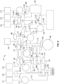
- Figs. 1-58 show components of a blood or fluid separation system that embodies various aspects of the present subject matter.
- the system includes two principal components, a durable and reusable blood separation device 10 ( Fig. 1 ) and a disposable fluid flow circuit 12 ( Fig. 2 ).
- the blood separation device 10 includes a spinning membrane separator drive unit 14 ( Fig. 1 ), a centrifuge or centrifugal separator 16 ( Fig. 3 ), additional components that control fluid flow through the disposable flow circuit 12, and a controller 18 ( Fig. 1 ), which governs the operation of the other components of the blood separation device 10 to perform a blood processing and collection procedure selected by the operator, as will be described in greater detail
- the blood separation device 10 ( Fig. 1 ) is configured as a durable item that is capable of long-term use. It should be understood that the blood separation device 10 of Fig. 1 is merely exemplary of one possible configuration and that blood separation devices according to the present disclosure may be differently configured.
- the blood separation device 10 is embodied in a single housing or case 20.
- the illustrated case 20 includes a generally horizontal portion 22 (which may include an inclined or angled face or upper surface for enhanced visibility and ergonomics) and a generally vertical portion 24.
- the spinning membrane separator drive unit 14 and the centrifugal separator 16 are shown as being incorporated into the generally horizontal portion 22 of the case 20, while the controller 18 is shown as being incorporated into the generally vertical portion 24.
- the configuration and operation of the spinning membrane separator drive unit 14, the centrifugal separator 16, the controller 18, and selected other components of the blood separation device 10 will be described in greater detail.
- the generally horizontal portion 22 is intended to rest on an elevated, generally horizontal support surface (e.g., a countertop or a tabletop), but it is also within the scope of the present disclosure for the case 20 to include a support base to allow the case 20 to be appropriately positioned and oriented when placed onto a floor or ground surface. It is also within the scope of the present disclosure for the case 20 to be mounted to a generally vertical surface (e.g., a wall), by either fixedly or removably securing the generally vertical portion 24 of the case 20 to the surface.
- a generally vertical surface e.g., a wall
- the case 20 may be configured to assume only the position or configuration of Fig. 1 or may be configured to move between two or more positions or configurations.
- the generally horizontal and vertical portions 22 and 24 are joined by a hinge or pivot, which allows the case 20 to be moved between a functional or open configuration ( Fig. 1 ) in which the generally vertical portion 24 is oriented at approximately 90 degrees to the generally horizontal portion 22 and a transport or closed configuration in which the generally vertical portion 24 is rotated about the hinge to approach the generally horizontal portion 22.
- the generally vertical portion 24 may be considered to be the lid of the case 20, while the generally horizontal portion 22 may be considered to be the base.
- the case 20 may include a latch for releasably locking the case 20 in its closed configuration and/or a handle, which the operator can grasp for transporting the case 20 in its closed configuration.
- the blood separation device 10 While it may be advantageous for the blood separation device 10 to be embodied in a compact, portable case 20, it is also within the scope of the present disclosure for the blood separation device to be embodied in a larger case or fixture that is intended to be installed in a single location and remain in that location for an extended period of time. If the blood separation device is provided as a fixture, it may be provided with more components and functionality than a more portable version.
- the illustrated blood separation device 10 includes a spinner support or spinning membrane separator drive unit 14 ( Fig. 1 ) for accommodating a generally cylindrical spinning membrane separator 26 of the fluid flow circuit 12.
- a spinner support or spinning membrane separator drive unit 14 ( Fig. 1 ) for accommodating a generally cylindrical spinning membrane separator 26 of the fluid flow circuit 12.
- U.S. Patent No. 5,194,145 describes an exemplary spinning membrane separator drive unit that would be suitable for incorporation into the blood separation device 10, but it should be understood that the spinning membrane separator drive unit 14 may be differently configured without departing from the scope of the present disclosure.
- the illustrated spinning membrane separator drive unit 14 has a base 28 configured to receive a lower portion of the spinning membrane separator 26 and an upper end cap 30 to receive an upper portion of the spinning membrane separator 26.
- the upper end cap 30 is positioned directly above the base 28 to orient a spinning membrane separator 26 received by the spinning membrane separator drive unit 14 vertically and to define a vertical axis about which the spinning membrane separator 26 is spun. While it may be advantageous for the spinning membrane separator drive unit 14 to vertically orient a spinning membrane separator 26, it is also within the scope of the present disclosure for the spinning membrane separator 26 to be differently oriented when mounted to the blood separation device 10.
- one of the components of the spinning membrane separator drive unit 14 is movable with respect to the other component, which may allow differently sized spinning membrane separators 26 to be received by the spinning membrane separator drive unit 14.
- the upper end cap 30 may be translated vertically with respect to the base 28 and locked in a plurality of different positions, with each locking position corresponding to a differently sized spinning membrane separator 26.
- At least one of the base 28 and the upper end cap 30 is configured to spin one or more components of the spinning membrane separator 26 about the axis defined by the spinning membrane separator drive unit 14.
- the mechanism by which the spinning membrane separator drive unit 14 spins one or more components of the spinning membrane separator 26 may vary without departing from the scope of the present disclosure.
- a component of the spinning membrane separator 26 to be spun includes at least one element configured to be acted upon by a magnet (e.g., a metallic material), while the spinning membrane separator drive unit 14 includes a magnet (e.g., a series of magnetic coils or semicircular arcs).
- the component or components of the spinning membrane separator 26 may be made to spin in different directions and at varying speeds. In other embodiments, different mechanisms may be employed to spin the component or components of the spinning membrane separator 26.
- the component or components of the spinning membrane separator 26 is preferably spun at a speed that is sufficient to create Taylor vortices in a gap between the spinning component and a stationary component of the spinning membrane separator 26 (or a component that spins at a different speed). Fluid to be separated within the spinning membrane separator 26 flows through this gap, and filtration may be dramatically improved by the creation of Taylor vortices.
- the centrifugal separator 16 includes a centrifuge compartment 32 that may receive the other components of the centrifugal separator 16 ( Fig. 3 ).
- the centrifuge compartment 32 may include a lid 34 that is opened to insert and remove a centrifugal separation chamber 36 of the fluid flow circuit 12.
- the lid 34 may be closed with the centrifugal separation chamber 36 positioned within the centrifuge compartment 32, as the centrifugal separation chamber 36 is spun or rotated about an axis 38 under the power of an electric drive motor or rotor 40 of the centrifugal separator 16.
- the particular configuration and operation of the centrifugal separator 16 depends upon the particular configuration of the centrifugal separation chamber 36 of the fluid flow circuit 12.
- the centrifugal separator 16 is similar in structure and operation to that of the ALYX system manufactured by Fenwal, Inc. of Lake Zurich, Illinois, which is an affiliate of Fresenius Kabi AG of Bad Homburg, Germany, as described in greater detail in U.S. Patent No. 8,075,468 .
- the centrifugal separator 16 may include a carriage or support 42 that holds the centrifugal separation chamber 36 and a yoke member 44.
- the yoke member 44 engages an umbilicus 46 of the fluid flow circuit 12, which extends between the centrifugal separation chamber 36 and a cassette 48 of the fluid flow circuit 12 ( Fig. 4 ).
- the yoke member 44 causes the umbilicus 46 to orbit around the centrifugal separation chamber 36 at a one omega rotational speed.
- the umbilicus 46 twists about its own axis as it orbits around the centrifugal separation chamber 36.
- the twisting of the umbilicus 46 about its axis as it rotates at one omega with the yoke member 44 imparts a two omega rotation to the centrifugal separation chamber 36, according to known design.
- the relative rotation of the yoke member 44 at a one omega rotational speed and the centrifugal separation chamber 36 at a two omega rotational speed keeps the umbilicus 46 untwisted, avoiding the need for rotating seals.
- Blood is introduced into the centrifugal separation chamber 36 by the umbilicus 46, with the blood being separated (e.g., into a layer of less dense components, such as platelet-rich plasma, and a layer of more dense components, such as packed red blood cells) within the centrifugal separation chamber 36 as a result of centrifugal forces as it rotates.
- Components of an interface monitoring system may be positioned within the centrifuge compartment 32 to oversee separation of blood within the centrifugal separation chamber 36.
- the interface monitoring system may include a light source 50 and a light detector 52, which is positioned and oriented to receive at least a portion of the light emitted by the light source 50.
- the light source 50 and the light detector 52 are positioned on stationary surfaces of the centrifuge compartment 32, but it is also within the scope of the present disclosure for one or both to be mounted to a movable component of the centrifugal separator 16 (e.g., to the yoke member 44, which rotates at a one omega speed).
- a movable component of the centrifugal separator 16 e.g., to the yoke member 44, which rotates at a one omega speed.
- the orientation of the various components of the interface monitoring system depends at least in part on the particular configuration of the centrifugal separation chamber 36, which will be described in greater detail herein.
- the light source 50 emits a light beam (e.g., a laser light beam) through the separated blood components within the centrifugal separation chamber 36 (which may be formed of a material that substantially transmits the light or at least a particular wavelength of the light without absorbing it). A portion of the light reaches the light detector 52, which transmits a signal to the controller 18 that is indicative of the location of an interface between the separated blood components.
- a light beam e.g., a laser light beam
- the light detector 52 which transmits a signal to the controller 18 that is indicative of the location of an interface between the separated blood components.
- controller 18 determines that the interface is in the wrong location (which can affect the separation efficiency of the centrifugal separator 16 and/or the quality of the separated blood components), then it can issue commands to the appropriate components of the blood separation device 10 to modify their operation so as to move the interface to the proper location.
- the blood separation device 10 may include other components compactly arranged to aid blood processing.
- the generally horizontal portion 22 of the case 20 of the illustrated blood separation device 10 includes a cassette station 54, which accommodates a cassette 48 of the fluid flow circuit 12 ( Fig. 4 ).
- the cassette station 54 is similarly configured to the cassette station of U.S. Patent No. 5,868,696 , but is adapted to include additional components and functionality.
- the illustrated cassette station 54 includes a plurality of clamps or valves V1-V9 ( Fig. 1 ), which move between a plurality of positions (e.g., between a retracted or lowered position and an actuated or raised position) to selectively contact or otherwise interact with corresponding valve stations C1-C9 of the cassette 48 of the fluid flow circuit 12 ( Figs. 2 and 4 ).
- its cassette 48 may not include a valve station C1-C9 for each valve V1-V9 of the cassette station 54, in which case fewer than all of the valves V1-V9 will be used in a separation procedure.
- a valve V1-V9 engages the associated valve station C1-C9 to prevent fluid flow through that valve station C1-C9 (e.g., by closing one or more ports associated with the valve station C1-C9, thereby preventing fluid flow through that port or ports).
- a valve V1-V9 is disengaged from the associated valve station C1-C9 (or less forcefully contacts the associated valve station C1-C9 than when in the actuated position) to allow fluid flow through that valve station C1-C9 (e.g., by opening one or more ports associated with the valve station C1-C9, thereby allowing fluid flow through that port or ports).
- valves V10 and V11 may be positioned outside of the cassette station 52 to interact with portions or valve stations C10 and C11 (which may be lengths of tubing) of the fluid flow circuit 12 to selectively allow and prevent fluid flow therethrough.
- the valves V1-V9 and corresponding valve stations C1-C9 of the cassette station 54 and cassette 48 may be differently configured and operate differently from the valves V10 and V11 and valve stations C10 and C11 that are spaced away from the cassette station 54.
- the cassette station 54 may be provided with additional components, such as pressure sensors A1-A4, which interact with sensor stations S1-S4 of the cassette 48 to monitor the pressure at various locations of the fluid flow circuit 12.
- pressure sensors A1-A4 may be configured to monitor the pressure.
- Other pressure sensors A1-A4 may monitor the pressure of the spinning membrane separator 26 and the centrifugal separation chamber 36.
- the controller 18 may receive signals from the pressure sensor A1-A4 that are indicative of the pressure within the fluid flow circuit 12 and, if a signal indicates a low- or high-pressure condition, the controller 18 may initiate an alarm or error condition to alert an operator to the condition and/or to attempt to bring the pressure to an acceptable level without operator intervention.
- the blood separation device 10 may also include a plurality of pumps P1-P6 (which may be collectively referred to as a pump assembly) cause fluid to flow through the fluid flow circuit 12.
- the pumps P1-P6 may be differently or similarly configured and/or function similarly or differently from each other.
- the pumps P1-P6 are configured as peristaltic pumps, which may be generally configured as described in U.S. Patent No. 5,868,696 .
- Each pump P1-P6 engages a different tubing loop T1-T6 extending from a side surface of the cassette 48 ( Fig. 4 ) and may be selectively operated under command of the controller 18 to cause fluid to flow through a portion of the fluid flow circuit 12, as will be described in greater detail.
- all or a portion of the cassette station 54 may be capable of translational motion in and out of the case 20 to allow for automatic loading of the tubing loops T1-T6 into the associated pump P1-P6.
- the illustrated blood separation device 10 also includes a centrifugal separator sensor M1 for determining one or more properties of fluids flowing out of and/or into the centrifugal separator 16. If the fluid flowing out of the centrifugal separator 16 includes red blood cells, the centrifugal separator sensor M1 may be configured to determine the hematocrit of the fluid. If the fluid flowing out of the centrifugal separator 16 is platelet-rich plasma, the centrifugal separator sensor M1 may be configured to determine the platelet concentration of the platelet-rich plasma. The centrifugal separator sensor M1 may detect the one or more properties of a fluid by optically monitoring the fluid as it flows through tubing of the fluid flow circuit 12 or by any other suitable approach.
- the controller 18 may receive signals from the centrifugal separator sensor M1 that are indicative of the one or more properties of fluid flowing out of the centrifugal separator 16 and use the signals to optimize the separation procedure based upon that property or properties. If the property or properties is/are outside of an acceptable range, then the controller 18 may initiate an alarm or error condition to alert an operator to the condition.
- a suitable device and method for monitoring hematocrit and/or platelet concentration is described in U.S. Patent No. 6,419,822 , but it should be understood that a different approach may also be employed for monitoring hematocrit and/or platelet concentration of fluid flowing out of the centrifugal separator 16.
- the illustrated blood separation device 10 further includes a spinner outlet sensor M2, which accommodates tubing of the fluid flow circuit 12 that flows a separated substance out of the spinning membrane separator 26.
- the spinner outlet sensor M2 monitors the substance to determine one or more properties of the substance, and may do so by optically monitoring the substance as it flows through the tubing or by any other suitable approach.
- a supernatant or a combination of a supernatant, platelets, and smaller red blood cells may flow through the tubing as a waste product, in which case the spinner outlet sensor M2 may be configured to monitor the optical characteristics of the waste product for quality purposes, such as monitoring for cell loss or hemolysis.
- the illustrated blood separation device 10 also includes an air detector M3 (e.g., an ultrasonic bubble detector), which accommodates tubing of the fluid flow circuit 12 that flows fluid to a recipient (such as a blood container). It may be advantageous to prevent air from reaching the recipient, so the air detector M3 may transmit signals to the controller 18 that are indicative of the presence or absence of air in the tubing. If the signal is indicative of air being present in the tubing, the controller 18 may initiate an alarm or error condition to alert an operator to the condition and/or to take corrective action to prevent the air from reaching the recipient (e.g., by reversing the flow of fluid through the tubing or diverting flow to a vent location).
- an air detector M3 e.g., an ultrasonic bubble detector
- the generally vertical portion 24 of the case 18 may include a plurality of weight scales W1-W6 (six are shown, but more or fewer may be provided), each of which may support one or more fluid containers F1-F7 of the fluid flow circuit 12 ( Fig. 2 ).
- the containers F1-F7 receive blood components or waste products separated during processing or intravenous fluids or additive fluids.
- Each weight scale W1-W6 transmits to the controller 18 a signal that is indicative of the weight of the fluid within the associated container F1-F7 to track the change of weight during the course of a procedure. This allows the controller 18 to process the incremental weight changes to derive fluid processing volumes and flow rates and subsequently generate signals to control processing events based, at least in part, upon the derived processing volumes. For example, the controller 18 may diagnose leaks and obstructions in the fluid flow circuit 12 and alert an operator.
- the illustrated case 20 is also provided with a plurality of hooks or supports H1 and H2 that may support various components of the fluid flow circuit 12 or other suitably sized and configured objects.
- the blood separation device 10 includes a controller 18, which is suitably configured and/or programmed to control operation of the blood separation device 10.
- the controller 18 comprises a main processing unit (MPU), which can comprise, e.g., a Pentium TM type microprocessor made by Intel Corporation, although other types of conventional microprocessors can be used.
- MPU main processing unit
- the controller 18 may be mounted inside the generally vertical portion 24 of the case 20, adjacent to or incorporated into an operator interface station (e.g., a touchscreen).
- the controller 18 and operator interface station may be associated with the generally horizontal portion 22 or may be incorporated into a separate device that is connected (either physically, by a cable or the like, or wirelessly) to the blood separation device 10.
- the controller 18 is configured and/or programmed to execute at least one blood processing application but, more advantageously, is configured and/or programmed to execute a variety of different blood processing applications.
- the controller 18 may be configured and/or programmed to carry out one or more of the following: a double unit red blood cell collection procedure, a plasma collection procedure, a plasma/red blood cell collection procedure, a red blood cell/platelet/plasma collection procedure, a platelet collection procedure, a platelet/plasma collection procedure, and (as will be described in detail herein) an MNC collection procedure. Additional or alternative procedure applications can be included without departing from the scope of the present disclosure.
- the controller 18 is configured and/or programmed to control one or more of the following tasks: drawing blood into a fluid flow circuit 12 mounted to the blood separation device 10, conveying blood through the fluid flow circuit 12 to a location for separation (i.e., into a spinning membrane separator 26 or centrifugal separation chamber 36 of the fluid flow circuit 12), separating the blood into two or more components as desired, and conveying the separated components into storage containers, to a second location for further separation (e.g., into whichever of the spinning membrane separator 26 and centrifugal separation chamber 36 that was not used in the initial separation stage), or to a recipient (which may be the source from which the blood was originally drawn).
- This may include instructing the spinning membrane separator drive unit 14 and/or the centrifugal separator 16 to operate at a particular rotational speed and instructing a pump P1-P6 to convey fluid through a portion of the fluid flow circuit 12 at a particular flow rate.
- a particular component of the blood separation device 10 e.g., the spinning membrane separator drive unit 14 or the centrifugal separator 16
- that component is being controlled by the controller 18 to perform that function.
- a procedure may call for the use of both the centrifugal separator 16 and the spinning membrane separator drive unit 14, in which case a properly programmed controller 18 is especially important to coordinate the operation of these two components, along with the other components of the blood separation device 10 to ensure that flow to and from the centrifugal separator 16 and spinning membrane separator drive unit 14 is at the proper level and that the components are functioning properly to process the blood circulating through the fluid flow circuit 12.
- the controller 18 may receive signals from various components of the blood separation device 10 (e.g., the pressure sensors A1-A4) to monitor various aspects of the operation of the blood separation device 10 and characteristics of the blood and separated blood components as they flow through the fluid flow circuit 12. If the operation of any of the components and/or one or more characteristics of the blood or separated blood components is outside of an acceptable range, then the controller 18 may initiate an alarm or error condition to alert the operator and/or take action to attempt to correct the condition. The appropriate corrective action will depend upon the particular error condition and may include action that is carried out with or without the involvement of an operator.
- the controller 18 may receive signals from various components of the blood separation device 10 (e.g., the pressure sensors A1-A4) to monitor various aspects of the operation of the blood separation device 10 and characteristics of the blood and separated blood components as they flow through the fluid flow circuit 12. If the operation of any of the components and/or one or more characteristics of the blood or separated blood components is outside of an acceptable range, then the controller 18 may initiate an alarm or error condition to alert the operator and/or
- the controller 18 may include an interface control module, which receives signals from the light detector 52 of the interface monitoring system.
- the signals that the controller 18 receives from the light detector 52 are indicative of the location of an interface between the separated blood components within the centrifugal separation chamber 36. If the controller 18 determines that the interface is in the wrong location, then it can issue commands to the appropriate components of the blood separation device 10 to modify their operation so as to move the interface to the proper location.
- the controller 18 may instruct one of the pumps P1-P6 to cause blood to flow into the centrifugal separation chamber 36 at a different rate and/or for a separated blood component to be removed from the centrifugal separation chamber 36 at a different rate and/or for the centrifugal separation chamber 36 to be spun at a different speed by the centrifugal separator 16.
- the interface control module in adjusting the position of the interface within the centrifugal separation chamber 36 will be described in greater detail with respect to an exemplary centrifugal separation chamber 36.
- an operator interface station associated with the controller 18 allows the operator to view on a screen or display (in alpha-numeric format and/or as graphical images) information regarding the operation of the system.
- the operator interface station also allows the operator to select applications to be executed by the controller 18, as well as to change certain functions and performance criteria of the system.
- the screen of the operator interface station can receive input from an operator via touch-activation. Otherwise, if the screen is not a touchscreen, then the operator interface station may receive input from an operator via a separate input device, such as a computer mouse or keyboard. It is also within the scope of the present disclosure for the operator interface station to receive input from both a touchscreen and a separate input device, such as a keypad.
- the fluid flow circuit or flow set 12 ( Fig. 2 ) it is intended to be a sterile, single use, disposable item.
- the operator loads various components of the fluid flow circuit 12 in the case 20 in association with the blood separation device 10.
- the controller 18 implements the procedure based upon preset protocols, taking into account other input from the operator.
- the operator removes the fluid flow circuit 12 from association with the blood separation device 10.
- the portions of the fluid flow circuit 12 holding the collected blood component or components are removed from the case 20 and retained for storage, transfusion, or further processing.
- the remainder of the fluid flow circuit 12 is removed from the case 20 and discarded.
- the fluid flow circuit 12 includes a cassette 48 ( Fig. 4 ), to which the other components of the fluid flow circuit 12 are connected by flexible tubing.
- the other components may include a plurality of fluid containers F1-F7 (for holding blood, a separated blood component, an intravenous fluid, or an additive solution, for example), one or more blood source access devices (e.g., a connector for accessing blood within a fluid container), and a spinning membrane separator 26 ( Figs. 8 and 9 ) and/or a centrifugal separation chamber 36 ( Figs. 10-17 ).
- the cassette 48 ( Fig. 4 ) provides a centralized, programmable, integrated platform for all the pumping and many of the valving functions required for a given blood processing procedure.
- the cassette 48 is similarly configured to the cassette of U.S. Patent No. 5,868,696 , but is adapted to include additional components (e.g., more tubing loops T1-T6) and functionality.
- the cassette 48 is mounted to the cassette station 54 of the blood separation device 10, with a flexible diaphragm of the cassette 48 placed into contact with the cassette station 54.
- the flexible diaphragm overlays an array of interior cavities formed by the body of the cassette 48.
- the different interior cavities define sensor stations S1-S4, valve stations C1-C9, and a plurality of flow paths.
- the side of the cassette 48 opposite the flexible diaphragm may be sealed by another flexible diaphragm or a rigid cover, thereby sealing fluid flow through the cassette 48 from the outside environment.
- Each sensor station S1-S4 is aligned with an associated pressure sensor A1-A4 of the cassette station 54, with each pressure sensor A1-A4 capable of monitoring the pressure within the associated sensor station S1-S4.
- Each valve station C1-C9 is aligned with an associated valve V1-V9, and may define one or more ports that allow fluid communication between the valve station C1-C9 and another interior cavity of the cassette 48 (e.g., a flow path).
- each valve V1-V9 is movable under command of the controller 18 to move between a plurality of positions (e.g., between a retracted or lowered position and an actuated or raised position) to selectively contact the valve stations C1-C9 of the cassette 48.
- a valve V1-V9 engages the associated valve station C1-C9 to close one or more of its ports to prevent fluid flow therethrough.
- a valve V1-V9 is disengaged from the associated valve station C1-C9 (or less forcefully contacts the associated valve station C1-C9 than when in the actuated position) to open one or more ports associated with the valve station C1-C9, thereby allowing fluid flow therethrough.
- tubing loops T1-T6 extend from the side surface of the cassette 48 to interact with pumps P1-P6 of the blood separation device 10.
- six tubing loops T1-T6 extend from the cassette 48 to be received by a different one of six pumps P1-P6, but in other embodiments, a procedure may not require use of all of the pumps P1-P6, in which case the cassette 48 may include fewer than six tubing loops.
- the different pumps P1-P6 may interact with the tubing loops T1-T6 of the cassette 48 to perform different tasks during a separation procedure (as will be described in greater detail), but in one embodiment, a different one of the pumps P1-P6 may be configured to serve as an anticoagulant pump P1, a source pump P2, a recirculation pump P3, a transfer pump P4, a plasma pump P5, and a waste pump P6. Certain procedures require fewer than all of the sensor stations, valve stations, and/or tubing loops illustrated in the exemplary cassette 48 of Fig. 4 , such that it should be understood that the cassettes of different fluid flow circuits 12 may be differently configured (e.g., with fewer sensor stations, valve stations, and/or tubing loops) without departing from the scope of the present disclosure.
- Additional tubing extends from the side surface of the cassette 48 to connect to the other components of the fluid flow circuit 12, such as the various fluid containers F1-F5, the spinning membrane separator 26, and the centrifugal separation chamber 36.
- the number and content of the various fluid containers F1-F7 depends upon the procedure for which the fluid flow circuit 12 is used, with the fluid containers F1-F7 of one particular fluid flow circuit 12 and procedure being described in greater detail herein. If the fluid flow circuit 12 includes a centrifugal separation chamber 36, then the tubing connected to it (which includes one inlet tube and two outlet tubes) may be aggregated into an umbilicus 46 ( Fig. 3 ) that is engaged by the yoke member 44 of the centrifugal separator 16 (as described above) to cause the umbilicus 46 to orbit around and spin or rotate the centrifugal separation chamber 36 during a separation procedure.
- a manual clamp 56 may be associated with a line or lines leading to the blood source and/or fluid recipient
- a return line filter 58 e.g., a microaggregate filter
- filters may be positioned upstream of one or more of the fluid containers to remove a substance (e.g., leukocytes) from a separated component (e.g., red blood cells or platelets) flowing into the fluid container
- an air trap 62 may be positioned on a line upstream of the centrifugal separation chamber 36.
- a spinning membrane separator 26 is shown. As will be described in greater detail, the spinning membrane separator 26 may be used for washing a mononuclear cell product (including T-cell lymphocytes).
- the spinning membrane separator 26 is associated with the remainder of the fluid flow circuit 12 by an inlet port 64 and two outlet ports 66 and 68.
- the inlet port 64 is shown as being associated with a bottom end or portion of the spinning membrane separator 26, while the outlet ports 66 and 68 are associated with an upper end or portion of the spinning membrane separator 26, but it is within the scope of the present disclosure for the spinning membrane separator 26 to be inverted, with fluid entering an upper end or portion of the spinning membrane separator 26 and fluid exiting a lower end or portion of the spinning membrane separator 26.
- the illustrated spinning membrane separator 26 includes a generally cylindrical housing 70 mounted concentrically about a longitudinal vertical central axis.
- An internal member or rotor 72 is mounted concentrically with the central axis.
- the housing 70 and rotor 72 are relatively rotatable, as described above with respect to the spinning membrane separator drive unit 14.
- the housing 70 is stationary and the rotor 72 is a rotating spinner that is rotatable concentrically within the cylindrical housing 70.
- the housing 70 (or at least its upper and lower ends) are formed of non-magnetic material, while the rotor 72 includes an element (e.g., a metallic material) that interacts with a magnet of the spinning membrane separator drive unit 14 to rotate the rotor 72 within the housing 70, as described above.
- an element e.g., a metallic material
- the boundaries of the blood flow path are generally defined by the gap 74 between the interior surface of the housing 70 and the exterior surface of the rotor 72, which is sometimes referred to as the shear gap.
- a typical shear gap 74 may be approximately 0.025-0.050 inches (0.067-0.127 cm) and may be of a uniform dimension along the axis, for example, where the axis of the housing 70 and rotor 72 are coincident.
- the width of the shear gap 74 also may vary along the axial direction, for example with the width of the gap 74 increasing in the direction of flow to limit hemolysis. Such a gap width may range from about 0.025 to about 0.075 inches (0.06-0.19 cm).
- the axes of the housing 70 and rotor 72 are coincident, with the outer diameter of the rotor 72 decreasing in the direction of flow, while the inner diameter of the housing 70 remaining constant.
- the inner diameter of the housing 70 may increase while the outer rotor diameter remains constant or both surfaces may vary in diameter.
- the gap width may be about 0.035 inches (0.088 cm) at the upstream or inlet end of the gap 74 and about 0.059 inches (0.15 cm) at the downstream end or terminus of the gap 74.
- the gap width could change linearly or stepwise or in some other manner as may be desired.
- the width dimension of the gap 74 is preferably selected so that at the desired relative rotational speed, Taylor-Couette flow, such as Taylor vortices, are created in the gap 74 and hemolysis is limited.
- a fluid to be washed is fed into the gap 74 by the inlet port 64 ( Fig. 8 ), which directs the fluid into the fluid flow entrance region at or adjacent to the bottom end of the spinning membrane separator 26.
- the spinning membrane separator drive unit 14 causes relative rotation of the housing 70 and rotor 72, creating Taylor vortices within the gap 74.
- the outer surface of the rotor 72 and/or the inner surface of the housing 70 is at least partially (and more preferably, substantially or entirely) covered by a cylindrical porous membrane 76 (shown in Fig. 9 as being mounted to the outer surface of the rotor 72).
- spinning membrane separator does not necessarily require that the membrane 76 is mounted to a component of the spinning membrane separator 26 that spins, but may also include a device in which the membrane 76 is mounted to a stationary component that includes another component that rotates with respect to the stationary membrane 76.
- the membrane 76 typically has a nominal pore size that may vary, depending on the nature of the substances to be removed. For example, if only a supernatant is to be filtered out during cell washing of an MNC product, then a nominal pore size of 0.65-0.8 microns may be employed. In another example, in which supernatant, platelets, and some smaller red blood cells are to be filtered out, a nominal pore size of 4.0 microns may be advantageous. It should be understood that these are only exemplary and that membranes having other pore sizes may alternatively be used without departing from the scope of the present disclosure.
- Membranes useful in the methods described herein may be fibrous mesh membranes, cast membranes, track-etched membranes or other types of membranes that will be known to those of skill in the art.
- the membrane 76 may have a polyester mesh (substrate) with nylon particles solidified thereon, thereby creating a tortuous path through which only certain sized components will pass.
- the membrane 76 may be made of a thin (approximately 15 micron thick) sheet of, for example, polycarbonate with pores or holes defined therein that are sized and configured to allow passage of only a selected one or more blood components.
- the outer surface of the rotor 72 may be shaped to define a series of spaced-apart circumferential grooves or ribs 78 separated by annular lands 80 ( Fig. 9 ).
- the surface channels defined by the circumferential grooves 78 are interconnected by longitudinal grooves 82. At one or both ends of the rotor 72, these grooves 78 are in communication with a central orifice or manifold 84.
- Pumping fluid into and out of the spinning membrane separator 26 causes the substance being filtered out (e.g., a supernatant) to flow through the membrane 76 and grooves 78, while the while remainder of the fluid (e.g., T-cells) remains within the gap 74 as fluid flows from the inlet port 64 at the bottom portion of the spinning membrane separator 26 toward the upper portion.
- Relative rotation of the rotor 72 and housing 70 causes a particular flow pattern within the gap 74 (described above) that enables filtration without clogging the membrane 76.
- the substance being filtered out exits the spinning membrane separator 26 via an outlet port 66 that is concentric with the rotational axis and in fluid communication with the central orifice 84 of the rotor 72 ( Fig. 9 ), with the substance flowing into a line associated with the outlet port 66.
- the remainder of the fluid exits the gap 74 via an outlet port 68 defined in the upper end or portion of the housing 70 and oriented generally tangentially to the gap 74 ( Fig. 8 ), flowing into a line associated with the outlet port 68.
- Fig. 8 shows a spinning membrane separator 26 having a rotor 72 with a spinner diameter D, a filtration length FL, and an overall length LOA.
- An exemplary smaller spinning membrane separator may have a spinner diameter D of approximately 1.1", a filtration length FL of approximately 3", and an overall length LOA of approximately 5.0".
- an exemplary larger spinning membrane separator may have a spinner diameter D of approximately 1.65", a filtration length FL of approximately 5.52", and an overall length LOA of approximately 7.7".
- An exemplary smaller spinning membrane separator is described in greater detail in U.S. Patent No. 5,194,145 , while an exemplary larger spinning membrane separator is described in greater detail in U.S. Patent Application Publication No. 2015/0218517 .
- a fluid flow circuit 12 may be provided with a centrifugal separation chamber 36 if platelets, white blood cells, and/or (as described herein) MNCs are to be separated and collected.
- An exemplary centrifugal separation chamber 36a is shown in Figs. 10 and 11 , while Fig. 12 illustrates the fluid flow path defined by the centrifugal separation chamber 36a.
- the body of the centrifugal separation chamber 36a is pre-formed in a desired shape and configuration (e.g., by injection molding) from a rigid, biocompatible plastic material, such as a non-plasticized medical grade acrylonitrile-butadiene-styrene (ABS).
- ABS non-plasticized medical grade acrylonitrile-butadiene-styrene
- centrifugal separation chamber 36a can be formed by separate molded parts, either by nesting cup-shaped subassemblies or two symmetric halves.
- the underside of the centrifugal separation chamber 36a includes a shaped receptacle 86 that is suitable for receiving an end of the umbilicus 46 of the fluid flow circuit 12 ( Fig. 3 ).
- a suitable receptacle 86 and the manner in which the umbilicus 46 may cooperate with the receptacle 86 to deliver fluid to and remove fluid from the centrifugal separation chamber 36a are described in greater detail in U.S. Patent No. 8,075,468 .
- the illustrated centrifugal separation chamber 36a has radially spaced apart inner (low-g) and outer (high-g) side wall portions 88 and 90, a bottom or first end wall portion 92, and a cover or second end wall portion 93.
- the cover 93 comprises a simple flat part that can be easily welded or otherwise secured to the body of the centrifugal separation chamber 36a. Because all features that affect the separation process are incorporated into one injection molded component, any tolerance differences between the cover 93 and the body of the centrifugal separation chamber 36a will not affect the separation efficiencies of the centrifugal separation chamber 36a.
- the wall portions 88 and 90, the bottom 92, and the cover 93 together define an enclosed, generally annular channel 94 ( Fig. 12 ).
- the (whole blood) inlet 96 communicating with the channel 94 is defined between opposing interior radial walls 98 and 100.
- One of the interior walls 98 joins the outer (high-g) wall portion 90 and separates the upstream and downstream ends of the channel 94.
- the interior walls 98 and 100 define the inlet passageway 96 of the centrifugal separation chamber 36a which, in one flow configuration, allows fluid to flow from the umbilicus 46 to the upstream end of the channel 94.
- the illustrated centrifugal separation chamber 36a further includes first and second outlets 102 and 104, respectively, which may be defined by opposing surfaces of interior radial walls. Both the first and second outlets 102 and 104 extend radially inward from the channel 94.
- the first (plasma) outlet 102 extends radially inward from an opening which, in the illustrated embodiment, is located at the inner side wall portion 88, while the second (red blood cell) outlet 104 extends radially inward from an opening that is associated with the outer side wall portion 90.
- the illustrated first outlet 102 is positioned adjacent to the inlet 96 (near the upstream end of the channel 94), while the second outlet 104 may be positioned at the opposite, downstream end of the channel 94.
- centrifugal separation chamber 36a illustrated in Fig. 10 is merely exemplary and that the centrifugal separation chamber 36 may be differently configured without departing from the scope of the present disclosure.
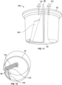
- Figs. 13 and 14 show an alternative embodiment of a centrifugal separation chamber 36b
- Fig. 15 illustrates the fluid flow path defined by the centrifugal separation chamber 36b.
- the centrifugal separation chamber 36b is similar to the centrifugal separation chamber 36a except for the location at which the inlet 96 opens into the channel 94.
- the inlet 96 opens into the channel 94 adjacent to the first end wall portion 92 (while the outlets 102 and 104 open into the channel 94 adjacent to the second end wall portion 93), as best shown in Figs. 11 and 12 .
- the inlet 96 of the centrifugal separation chamber 36b of Fig. 13 opens into the channel 94 adjacent to the second end wall portion 93 (along with the outlets 102 and 104), as best shown in Figs. 14 and 15 .
- the location at which the inlet 96 opens into the channel 94 may affect the separation of fluid within the channel 94, so the centrifugal separation chamber 36a of Fig. 10 may be preferable for certain procedures or for use in combination with certain blood separation devices, while the centrifugal separation chamber 36b of Fig. 13 may be preferable for other procedures or for use in combination with other blood separation devices.
- Figs. 16 and 17 show another exemplary embodiment of a centrifugal separation chamber 36c suitable for incorporation into a fluid flow circuit 12.
- the centrifugal separation chamber 36c is similar to the centrifugal separation chambers 36a and 36b of Figs. 10 and 13 except for the location at which the inlet 96 opens into the channel 94.
- the inlet 96 may open into the channel 94 at a location that is closer to the first end wall portion 92 than to the second end wall portion 93, at a location that is closer to the second end wall portion 93 than to the first end wall portion 92, or at a location that is equally spaced between the first and second end wall portions 92 and 93.
- the axial location at which the inlet 96 opens into the channel 94 may affect the separation of fluid within the channel 94, so the preferred location at which the inlet 96 opens into the channel 94 (which may also depend upon the nature of the blood separation device paired with the centrifugal separation chamber 36c) may be experimentally determined.
- Blood flowed into the channel 94 separates into an optically dense layer RBC and a less optically dense layer PLS ( Figs. 18-20 ) as the centrifugal separation chamber 36 is rotated about the rotational axis 38.
- the optically dense layer RBC forms as larger and/or heavier blood particles move under the influence of centrifugal force toward the outer (high-g) wall portion 90.
- the optically dense layer RBC will typically include red blood cells (and, hence, may be referred to herein as the "RBC layer") but, depending on the speed at which the centrifugal separation chamber 36 is rotated, other cellular components (e.g., larger white blood cells) may also be present in the optically dense layer RBC.
- the less optically dense layer PLS typically includes a plasma constituent, such as platelet-rich plasma or platelet-poor plasma (and, hence, will be referred to herein as the "PLS layer").
- a plasma constituent such as platelet-rich plasma or platelet-poor plasma (and, hence, will be referred to herein as the "PLS layer”).
- PLS layer a plasma constituent
- other components e.g., smaller white blood cells and anticoagulant
- other components may also be present in the less optically dense layer PLS.
- blood introduced into the channel 94 via the inlet 96 will travel in a generally clockwise direction (in the orientation of Fig. 10 ) as the optically dense layer RBC separates from the less optically dense layer PLS.
- the optically dense layer RBC continues moving in the clockwise direction as it travels the length of the channel 94 along the outer side wall portion 90, from the upstream end to the downstream end, where it exits the channel 94 via the second outlet 104.
- the less optically dense layer PLS separated from the optically dense layer RBC reverses direction, moving counterclockwise along the inner side wall portion 88 to the first outlet 102, adjacent to the inlet 96.
- the inner side wall portion 88 may be tapered inward as it approaches the second outlet 104 to force the plasma liberated at or adjacent to the downstream end of the channel 94 to drag the interface back towards the upstream end of the channel 94, where the lower surface hematocrit will re-suspend any platelets settled on the interface.
- the transition between the optically dense layer RBC and the less optically dense layer PLS may be referred to as the interface INT.
- the interface INT contains mononuclear cells and T-cell lymphocytes.
- the location of the interface INT within the channel 94 of the centrifugal separation chamber 36 can dynamically shift during blood processing, as Figs. 18-20 show. If the location of the interface INT is too high (that is, if it is too close to the inner side wall portion 88 and the first outlet 102, as in Fig. 19 ), red blood cells can flow into the first outlet 102, potentially adversely affecting the quality of the low density components (platelet-rich plasma or platelet-poor plasma).
- the collection efficiency of the system may be impaired.
- the ideal or target interface INT may be experimentally determined, which may vary depending on any of a number of factors (e.g., the configuration of the centrifugal separation chamber 36, the rate at which the centrifugal separation chamber 36 is rotated about the rotational axis 38, etc.). As will be described herein, it may be advantageous to temporarily move the interface INT away from the location of Fig. 18 during a separation procedure.
- the blood separation device 10 may include an interface monitoring system and a controller 18 with an interface control module to monitor and, as necessary, correct the position of the interface INT.
- the centrifugal separation chamber 36 is formed with a ramp 106 extending from the high-g wall portion 90 at an angle ⁇ across at least a portion of the channel 94 ( Figs. 10 and 18-20 ).
- the angle ⁇ , measured with respect to the rotational axis 38 is about 25° in one embodiment.
- Figs. 18-20 show the orientation of the ramp 106 when viewed from the low-g side wall portion 88 of the centrifugal separation chamber 36.
- the ramp 106 may be positioned at any of a number of locations between the upstream and downstream ends of the channel 94, but in one embodiment, the ramp 106 may be positioned generally adjacent to the first outlet 102, in the path of fluid and/or a fluid component moving from the inlet 96 to the first outlet 102.
- the ramp 106 makes the interface INT between the optically dense layer RBC and the less optically dense layer PLS more discernible for detection, displaying the optically dense layer RBC, less optically dense layer PLS, and interface INT for viewing through a light-transmissive portion of the centrifugal separation chamber 36.
- the ramp 106 and at least the portion of the centrifugal separation chamber 36 angularly aligned with the ramp 106 may be formed of a light-transmissive material, although it may be advantageous for the entire centrifugal separation chamber 36 to be formed of the same light-transmissive material.
- the light source 50 of the interface monitoring system is secured to a fixture or wall of the centrifuge compartment 32 and oriented to emit a light that is directed toward the rotational axis 38 of the centrifugal separator 16, as shown in Figs. 5-7 .
- the light detector 52 is positioned at an angle with respect to the light source 50 (as in the illustrated embodiment)
- the light L emitted by the light source 50 must be redirected from its initial path before it will reach the light detector 52.
- the light L is redirected by a reflector that is associated with a light-transmissive portion of the inner side wall portion 88, as shown in Figs. 5 and 6 .
- the reflector may be a separate piece that is secured to the inner side wall portion 88 (e.g., by being bonded thereto) or may be integrally formed with the body of the centrifugal separation chamber 36.
- the reflector may be a reflective surface, such as a mirror, that is oriented (e.g., at a 45° angle) to direct light L emitted by the light source 50 to the light detector 52.
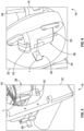
- the reflector is provided as a prismatic reflector 108 ( Figs. 7, 21, and 22 ), which is formed of a light-transmissive material (e.g., a clear plastic material) and has inner and outer walls 110 and 112 and first and second end walls 114 and 116 ( Fig. 21 ).
- the inner wall 110 is positioned against the inner side wall portion 88 of the centrifugal separation chamber 36 and is oriented substantially perpendicular to the initial path of the light L from the light source 50.
- the first end wall 114 is oriented at an angle (e.g., an approximately 45° angle) with respect to the first surface 110 and the second end wall 116, causing the light to be redirected within the prismatic reflector 108, rather than exiting the prismatic reflector 108 via the first end wall 114.
- the first end wall 114 directs the light L at an angle to its initial path (which may be an approximately 90° angle, directing it from a path toward the rotational axis 38 to a path that is generally parallel to the rotational axis 38) toward the second end wall 116 ( Fig. 22 ).
- the first end wall 114 and the inner and outer walls 110 and 112 of the prismatic reflector 108 may be configured to transmit the redirected light L from the first end wall 114 to the second end wall 116 by total internal reflection.
- the second end wall 116 is oriented substantially perpendicular to the redirected path of the light L through the prismatic reflector 108, such that the light L will exit the prismatic reflector 108 via the second end wall 116, continuing along its redirected path.
- the second end wall 116 is roughened or textured or otherwise treated or conditioned to diffuse the light L as it exits the prismatic reflector 108, which may better ensure that the light L reaches the light detector 52 ( Fig. 7 ).
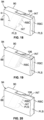
- the prismatic reflector 108 may be angularly aligned with the ramp 106, such that the light L from the light source 50 will only enter into the prismatic reflector 108 when the ramp 106 has been rotated into the path of the light L. At all other times (when the ramp 106 is not in the path of the light L), the light L will not reach the prismatic reflector 108 and, thus, will not reach the light detector 52. This is illustrated in Figs. 23-26 , which show the ramp 106 and prismatic reflector 108 as the centrifugal separation chamber 36 is rotated about the rotational axis 38 (while the light source 50 remains in a fixed location). In Fig.
- the ramp 106 and prismatic reflector 108 have not yet been rotated into the initial path of the light L from the light source 50. At this time, no light is transmitted to the light detector 52, such that the output voltage of the light detector 52 (i.e., the signal transmitted from the light detector 52 to the controller 18) is in a low- or zero-state ( Fig. 27 ).
- the light L Upon the ramp 106 first being rotated into the initial path of the light L from the light source 50 ( Fig. 24 ), the light L will begin to reach the prismatic reflector 108, which directs the light L to the light detector 52. This causes the voltage output of the light detector 52 (i.e., the signal transmitted from the light detector 52 to the controller 18) to increase to a non-zero value or state, as shown in Fig. 28 .
- the channel 94 is filled with a fluid that will transmit the light L rather than absorbing or reflecting the light or otherwise preventing the light L from reaching the prismatic reflector 108, such that the voltage output of the light detector 52 will remain generally constant as the ramp 106 and prismatic reflector 108 are rotated through the initial path of the light L from the light source 50 ( Figs. 25 and 29 ).
- a calibration phase may coincide with a priming phase during which saline is pumped through the fluid flow circuit 12 to prime the fluid flow circuit 12 or may comprise a separate phase.
- a calibration phase may be useful in ensuring the proper operation of the light source 50 and the light detector 52, standardizing the readings taken during a separation procedure in case of any irregularities or imperfections of the centrifugal separation chamber 36, and establishing a baseline value for the signal transmitted from the light detector 52 to the controller 18 when the ramp 106 and prismatic reflector 108 are aligned with the light source 50.
- the voltage output of the light detector 52 will typically not remain constant as the ramp 106 and prismatic reflector 108 are rotated through the initial path of the light L from the light source 50 because the different fluid layers displayed on the ramp 106 will allow different amounts of light L to reach the prismatic reflector 108.
- the ramp 106 and prismatic reflector 108 are eventually rotated out of alignment with the light source 50 ( Fig. 26 ), at which time no light L will reach the prismatic reflector 108 and the voltage output of the light detector 52 will return to its low- or zero-state ( Fig. 30 ).
- the light L may have a relatively small diameter for improved resolution of the signal that is generated by the light detector 52.
- the light L from the light source 50 travels through a light-transmissive portion of the outer side wall portion 90 and the ramp 106 to intersect the separated blood components thereon when the ramp 106 has been rotated into the initial path of the light L.
- the light continues through the channel 94 and the fluids in the channel 94.
- At least a portion of the light L i.e., the portion not absorbed or reflected by the fluids
- the light L passes through the inner side wall portion 88 and enters the prismatic reflector 108, which redirects the light L from its initial path to the light detector 50, as described above.
- the light L reaches the light detector 52 after intersecting and traveling through the separated blood components in the channel 94 only once, in contrast to known systems in which light from a light source travels through a ramp and a fluid-filled channel before being reflected back through the channel to reach a light detector.
- Requiring the light L to traverse the fluid-filled channel 94 only once before reaching the light detector 52 instead of twice may be advantageous in that it tends to increase the intensity of the light L that reaches the light detector 52, which may improve monitoring and correction of the interface location.
- the percentage of the ramp 106 occupied by the less optically dense layer PLS and by the optically dense layer RBC is not necessarily equal to the percentage of the channel 94 occupied by the less optically dense layer PLS and by the optically dense layer RBC, but that the percentage of the ramp 106 occupied by a separated blood component layer may be merely indicative of the percentage of the channel 94 occupied by that separated blood component layer.
- the amount of light L received by the light detector 52 (and, hence, the magnitude of the voltage output) after the light L has passed through the less optically dense layer PLS may be greater than, less than, or equal to the amount of light L received by the light detector 52 after passing through saline during the calibration phase described above.
- the voltage output of the light detector 52 will be generally uniform (at an elevated level) the whole time that the ramp 106 passes through the path of the light L before being exposed to the interface INT, as shown in Fig. 37 .
- the controller 18 may be programmed and/or configured to consider a signal that deviates from a maximum signal level (e.g., a 10% decrease) to be part of the elevated signal for purposes of calculating the pulse width of the signal.
- the controller 18 will treat a greater deviation (i.e., a greater decrease in the magnitude of the signal) as the end of the elevated signal for purposes of calculating the pulse width of the signal.
- the optically dense layer RBC will be positioned adjacent to the outer side wall portion 90 as it separates from the less optically dense layer PLS, such that the optically dense layer RBC will not be displayed on the ramp 106 until the ramp 106 is spaced a greater distance away from the inner side wall portion 88 (i.e., toward the right end of the ramp 106 in the orientation of Figs. 31-34 ).
- the voltage output or signal from the light detector 52 When receiving less light L, the voltage output or signal from the light detector 52 will decrease to a lower level than when the light L was passing through only the less optically dense layer PLS in the channel 94, as shown in Fig. 38 .
- the light detector 52 may be generating a signal or voltage output that is approximately equal to its zero-state (as in Fig. 35 , when the light detector 52 is receiving no light L) or a signal or voltage output that is some degree less than the magnitude of the signal or voltage output generated while the light L encounters only the less optically dense layer PLS in the channel 94.
- the controller 18 may be programmed and/or configured to recognize this lower level signal as representing the presence of the optically dense layer RBC on the ramp 106 (and in the portion of the channel 94 being traversed by the light L) and treat this lower level signal as the end point of the elevated signal generated by the light detector 52 while light L passes through only the less optically dense layer PLS in the channel 94.
- the pulse width of the elevated signal from the light detector 52 to the controller 18 is determined by the percentages of the ramp 106 that are occupied by the less optically dense layer PLS and the optically dense layer RBC. Accordingly, a greater pulse width of the signal from the light detector 52 to the controller 18 is associated with the less optically dense layer PLS occupying a larger portion of the ramp 106 (as shown in Fig. 39 from the point of view of the light source 50, which may correspond to the condition shown in Fig. 19 ) and will be indicative of a thinner optically dense layer RBC on the ramp 106 (and in the channel 94).
- a signal from the light detector 52 to the controller 18 having a narrower pulse width is associated with the less optically dense layer PLS occupying a smaller portion of the ramp 106 (as shown in Fig. 40 ) and will be indicative of a thicker optically dense layer RBC on the ramp 106 (and in the channel 94).
- the controller 18 may compare the pulse width of the signal to the pulse width generated during the calibration phase (described above and shown in Fig. 41 ), which corresponds to the pulse width when light L is transmitted to the light detector 52 over the entire width of the ramp 106.
- the pulse width of the signal generated by the light detector 52 during the calibration phase may be referred to as the saline calibration signal. Comparing these two pulse widths will indicate the percentage of the ramp 106 that is occupied by the less optically dense layer PLS and by the optically dense layer RBC, which information the controller 18 may use to determine the location of the interface INT within the channel 94.
- the interface position may be calculated as follows:
- Interface position (%) ((saline calibration pulse width - current plasma pulse width) / saline calibration pulse width) * 100 [Equation 1]
- Equation 1 effectively calculates the percentage of the ramp 106 that is occupied by the optically dense layer RBC, as the difference between the two pulse widths corresponds to the length of time that the ramp 106 is rotated through the path of the light L without the light detector 52 received an elevated level of light L (i.e., the amount of time that the ramp 106 is rotated through the path of the light L while the optically dense layer RBC is present on the ramp 106).
- the interface control module compares the actual interface location with a desired interface location, which may be referred to as the setpoint S.
- the difference between the setpoint S and the calculated interface position may be referred to as the error signal E, which is shown in Fig. 42 .
- the error signal E is shown in Fig. 42 .
- so expressing the error signal E in terms of a targeted red blood cell percentage value i.e., the percentage of the ramp 106 that is actually occupied by the optically dense layer RBC vs. the percentage of the ramp 106 which should be occupied by the optically dense layer RBC
- the error signal E may be expressed or calculated in any of a number of other ways.
- a negative error signal E indicates that the optically dense layer RBC on the ramp 106 is too large (as Fig. 19 shows).
- the interface control module of the controller 18 generates a signal to adjust an operational parameter accordingly, such as by reducing the rate at which platelet-rich plasma is removed through the first outlet 102 under action of a pump of the blood separation device 10.
- the interface INT moves toward the desired control position (as Fig. 18 shows), where the error signal is zero.
- a positive error signal indicates that the optically dense layer RBC on the ramp 106 is too small (as Figs. 20 and 42 show).
- the interface control module of the controller 18 generates a signal to adjust an operational parameter accordingly, such as by increasing the rate at which the plasma constituent is removed through the first outlet 102 under action of a pump of the blood separation device 10.
- the interface INT moves toward the desired control position ( Fig. 18 ), where the error signal is again zero.
- an operator selects the desired protocol (e.g., using an operator interface station, if provided), which informs the controller 18 of the manner in which it is to control the other components of the blood separation device 10 during the procedure.
- the desired protocol e.g., using an operator interface station, if provided
- the operator may also proceed to enter various parameters, such as information regarding the blood source.
- the operator also enters the target yield for the various blood components (which may also include entering a characteristic of the blood, such as a platelet pre-count) or some other collection control system (e.g., the amount of whole blood to be processed).
- any fluid containers e.g., a storage solution container
- they may be connected to the fluid flow circuit 12 (e.g., by piercing a septum of a tube of the fluid flow circuit 12 or via a luer connector), with the fluid flow circuit 12 then being mounted to the blood separation device 10 (including the fluid containers F1-F7 being hung from the weight scales W1-W6 and the hooks or supports H1 and H2, as appropriate).
- An integrity check of the fluid flow circuit 12 may be executed by the controller 18 to ensure the various components are properly connected and functioning.
- the blood source is connected to the fluid flow circuit 12 and the fluid flow circuit 12 may be primed (e.g., by saline pumped from a saline bag F2 by operation of one or more of the pumps P1-P6 of the blood separation device 10).
- the fluid flow circuit 12 may be primed (e.g., by saline pumped from a saline bag F2 by operation of one or more of the pumps P1-P6 of the blood separation device 10).
- blood separation may begin.
- the stages of blood separation vary depending on the particular procedure, and will be described in greater detail below.
- the blood separation device 10 may be used to separate and collect mononuclear cells and T-cell lymphocytes as an MNC product.
- the MNC product may be mixed with a formulation containing genetic material and passed through an electroporation device, which enables genetic editing of the T-cells of the MNC product.
- the MNC product may be washed before and/or after being passed through the electroporation device.
- Fig. 2 is a schematic view of an exemplary fluid flow circuit 12 having a pair of blood access devices (e.g., needles) for separating and collecting mononuclear cells and T-cell lymphocytes from blood as an MNC product.
- the fluid flow circuit 12 includes a cassette 48 of the type described above and illustrated in Fig. 4 , which connects the various components of the fluid flow circuit 12.
- the various connections amongst the components of the fluid flow circuit 12 are shown in Fig. 2 , which also shows the fluid flow circuit 12 mounted to the blood separation device 10.
- the fluid flow circuit 12 includes a fluid container F3 (which may be referred to as a first waste bag) that, in the illustrated procedures of Figs.
- the line L1 may include a manual clamp 56 that may initially be in a closed position to prevent fluid flow through the line L1.
- an operator may move the manual clamp 56 from its closed position to an open position to allow fluid flow through the line L1.
- the bulk or net platelet-rich plasma flow rate out of the centrifugal separation chamber 36 is equal to the flow rate of the plasma pump P5.
- Line L12 has a junction, where it splits into lines L13 and L14, with line L14 itself including a junction, where it splits into lines L15 and L16.
- a valve V7 associated with valve station C7 is closed to prevent fluid flow through the line L16, while the transfer pump P4 associated with line L15 is inactive, thereby directing the separated platelet-rich plasma through line L13 and the valve station C6 associated with open valve V6.
- the mononuclear cell-containing layer remains within the centrifugal separation chamber 36 and increases in volume throughout this phase while the packed red blood cells and the platelet-rich plasma are removed from the centrifugal separation chamber 36.
- This phase continues for a predetermined amount of time or until the occurrence of a predetermined event. In one embodiment, this phase continues until a predetermined volume of blood (e.g., 1,000-2,000 ml) has been processed, which is experimentally determined to be the blood volume that can be processed before mononuclear cells begin to escape the centrifugal separation chamber 36.
- a predetermined volume of blood e.g., 1,000-2,000 ml
- valve V1 associated with valve station C1 is closed, while the valve V4 associated with valve station C4 is opened, as shown in Fig. 44 .
- This phase lasts long enough to collect a specific volume of packed red blood cells, which are used to transfer the mononuclear cell-containing layer out of the centrifugal separation chamber 36, as will be described in greater detail herein. In one embodiment, approximately 50 ml of packed red blood cells is collected, although the particular volume may vary without departing from the scope of the present disclosure.
- the MNC transfer phase begins. This phase may begin by allowing the centrifugal separator 16 to rotate the centrifugal separation chamber 36 without flow for approximately 30-60 seconds to allow the mononuclear cell distribution along the interface between the platelet-rich plasma and the red blood cell layer in the centrifugal separation chamber 36 to stabilize.
- Blood draw is stopped during the MNC transfer phase by closing the valve V10 associated with valve station C10, while also ceasing operation of the anticoagulant pump P1 and the source pump P2, as shown in Fig. 45 .
- the valve V3 associated with valve station C3 is opened to allow saline to flow out of the saline container F2 via gravity.
- the saline flows through line L3 and to the blood source via line L1 to prevent coagulation of any blood present in the fistula of line L1 that has not yet been anticoagulated.
- the centrifugal separator 16 continues to rotate the centrifugal separation chamber 36 at the same speed as during the MNC collection phase (e.g., approximately 4,500 rpm), such that the returning packed red blood cells quickly increase the thickness of the red blood cell layer within the centrifugal separation chamber 36.
- This causes the mononuclear cell-containing layer on top of the red blood cell layer to exit the centrifugal separation chamber 36 via line L10 (i.e., the plasma outlet).
- line L10 i.e., the plasma outlet
- no fluid will exit the centrifugal separation chamber 36 via line L4 (i.e., the inlet) due to the source pump P2 and the recirculation pump P3 being inactive.
- the valve V7 associated with valve station C7 opens and the valve V6 associated with valve station C6 closes, as shown in Fig. 46 .
- This will direct the fluid in line L10 (i.e., the mononuclear cell-containing layer) through lines L14 and L16 and into the MNC collection container F5.
- centrifugal separator sensor M1 detects that the fluid in line L10 is packed red blood cells (due to detection of an elevated optical density and/or redness level), this phase is ended to prevent packed red blood cells from flowing into the MNC collection container F5.
- the collected red blood cells are conveyed into the centrifugal separation chamber 36 via the red blood cell outlet (i.e., line L5) to harvest mononuclear cells and T-cell lymphocytes.
- the red blood cell outlet i.e., line L5
- collected red blood cells instead enter a blood separation chamber via a whole blood inlet to harvest mononuclear cells.
- the approach described herein may be advantageous to the extent that a second inlet (or a fluid flow path between the red blood cell collection container and the whole blood inlet) are not required, which may reduce the number of components of the fluid flow circuit 12 and its complexity.
- a pump may be associated with line L5 to instead push the contents of the red blood cell collection container back into the centrifugal separation chamber 36 via line L5.
- lines L10 and L12 Upon completion of the MNC transfer phase, lines L10 and L12 will contain mostly packed red blood cells (which were used to push the mononuclear cell-containing layer out of the centrifugal separation chamber 36), while lines L14 and L16 will contain mononuclear cells and T-cell lymphocytes that were not conveyed all the way into the MNC collection container F5.
- a plasma flush phase is executed.
- the centrifugal separation chamber 36 is substantially entirely filled with packed red blood cells (in order to push the mononuclear cell-containing layer out of the centrifugal separation chamber 36).
- the red blood cell layer is instead brought to a lower thickness (as in Fig. 20 ) in order to cause platelet-poor plasma instead of platelet-rich plasma to exit the centrifugal separation chamber 36 via line L10 (i.e., the plasma outlet).
- the exact thickness of the red blood cell layer may vary without departing from the scope of the present disclosure, but it may be experimentally determined as the thickness at which platelet-poor plasma (instead of platelet-rich plasma) will tend to exit the centrifugal separation chamber 36 via line L10 (i.e., the plasma outlet).
- the thickness of the red blood cell layer is reduced to a level that is less than half of the typically preferred thickness of the red blood cell layer during separation.
- the thickness of the red blood cell layer is reduced to a level (e.g., approximately 20% or less of the total fluid thickness of the centrifugal separation chamber 36) that is approximately one-third of the thickness of the red blood cell layer that is typically preferred during separation (e.g., approximately 60% of the total fluid thickness of the centrifugal separation chamber 36).
- the plasma pump P5 is restarted (as shown in Fig. 48 ).
- the platelet-poor plasma exiting the centrifugal separation chamber 36 via line L10 clears the packed red blood cells remaining in lines L10 and L12 at the end of the MNC transfer phase.
- the platelet-poor plasma pushes the packed red blood cells from lines L10 and L12 to the blood source via lines L13, L18, and L9.
- Restarting the recirculation pump P3 begins to aid in the reestablishment of steady state separation (by increasing the separation efficiency of platelets from red blood cells and by increasing the thickness of the red blood cell layer within the centrifugal separation chamber 36) if an additional amount of mononuclear cells and T-cells is to be collected (by transitioning back into an MNC collection phase and repeating the foregoing procedure).
- the centrifugal separator sensor M1 may be used to determine when platelet-rich plasma (instead of platelet-poor plasma) begins exiting the centrifugal separation chamber 36 via line L10, at which point the plasma flush phase transitions to an MNC collection phase and the procedure is repeated.
- the observed thickness of the red blood cell layer within the centrifugal separation chamber 36 may also be a factor in determining when to transition from the plasma flush phase to an MNC collection phase.
- platelet-poor plasma created in the centrifugal separation chamber 36 during reestablishment of separation is used to flush mononuclear cells and T-cells from lines L14 and L16 into the MNC collection container F5.
- This is in contrast to conventional approaches, in which previously collected platelet-poor plasma is instead used to flush mononuclear cells into a collection container.
- the approach described herein may be advantageous to the extent that a platelet-poor plasma collection container is not required, which may reduce the number of components of the fluid flow circuit 12 and its complexity. Additionally, it is not necessary to execute a platelet-poor plasma collection phase. Furthermore, following one MNC collection cycle, separation must be reestablished in both the conventional procedure and the procedure described herein. By creating and using platelet-poor plasma during a phase that must occur regardless of the approach taken, the time required to complete the procedure may be reduced.
- the MNC product may be subjected to further processing, including electroporation-based treatment, such as CAR T-cell therapy.
- electroporation-based treatment such as CAR T-cell therapy.
- This may be carried out using a standalone, multifunctional device configured to execute the various steps of an electroporation-based treatment (including addition of DNA, electroporation, and cell washing), as is shown in Figs. 50 and 51 .
- this may be carried out using a dedicated electroporation device, which is configured only for electroporation of T-cells, with the blood separation device 10 executing the other steps of the electroporation-based treatment, as shown in Figs. 52-58 .
- Figs. 50 and 51 show an MNC product being conveyed through a standalone, multifunctional device 118 ( Fig. 50 ) and then reinfused to the blood source ( Fig. 51 ).
- the exact configuration of the device 118 may vary without departing from the scope of the present disclosure, but it is configured to perform the various steps of an electroporation-based procedure (e.g., CAR T-cell therapy). This may include addition of DNA to the MNC product, electroporation of the MNC product (to open pores in a cell membrane of a T-cell, which allows the DNA to enter and modify the genome of the T-cell), and cell washing.
- a line or tubing or conduit of the fluid flow circuit 12 may be configured to be connected to the device 118 as an inlet, with at least a portion of the MNC product flowing into the device 118 via the inlet.
- Another line or tubing or conduit of the fluid flow circuit 12 may be configured to be connected to the device 118 as an outlet, with the modified MNC product exiting the device 118 via the outlet.
- the fluid flow circuit 12 may be configured as a closed system, with the fluid flow circuit 12 including a portion configured to be placed into, mounted onto, or otherwise associated with the device 118 (e.g., including one or more containers or vessels configured to be associated with the device 118), rather than a plurality of lines or tubes or conduits of the fluid flow circuit 12 being connected to the device 118.
- the MNC product is transferred to it from the MNC collection container F5 by operation of the transfer pump P4 ( Fig. 50 ).
- the valve V7 associated with valve station C7 is opened (if not already open), while the valve V6 associated with valve station C6 is closed (if not already closed).
- the plasma pump P5 is inactive, thus causing the transfer pump P4 to pull the MNC product out of the MNC collection container F5 via line L16, with the MNC product moving from line L16 toward the transfer pump P4 via line L15.
- Line L15 splits into lines L19 and L20 downstream of the transfer pump P4.
- Line L19 leads into the standalone, multi-functional device 118, while line L20 leads through the sensor station S4 associated with pressure sensor A4 and into the spinning membrane separator 26.
- the waste pump P6 downstream of the spinning membrane separator 26 is inactive, along with the valve V8 associated with valve station C8 being closed, which causes the MNC product in line L15 to move through line L19 into the device 118, rather than flowing through line L20.
- the MNC product passes through the device 118, where it is variously processed to edit the genomes of the T-cells.
- the processing carried out by the device 118 may include (without being limited to) the addition of DNA, cell washing, and electroporation (in various orders).
- the modified MNC product exits the device 118 via line L21.
- the valve V9 associated with valve station C9 is open, while the valve V5 associated with valve station C5 is closed, which directs the modified MNC product through line L22 instead of through line L17.
- Line 22 splits into lines L23 and L24.
- the valve V8 associated with valve station C8 is closed, thus preventing flow through line L23, while directing the modified MNC product through line L24 and into an in-process container F6.
Landscapes
- Health & Medical Sciences (AREA)
- Life Sciences & Earth Sciences (AREA)
- Heart & Thoracic Surgery (AREA)
- Engineering & Computer Science (AREA)
- Vascular Medicine (AREA)
- Biomedical Technology (AREA)
- General Health & Medical Sciences (AREA)
- Hematology (AREA)
- Anesthesiology (AREA)
- Animal Behavior & Ethology (AREA)
- Public Health (AREA)
- Veterinary Medicine (AREA)
- Chemical & Material Sciences (AREA)
- Organic Chemistry (AREA)
- Wood Science & Technology (AREA)
- Bioinformatics & Cheminformatics (AREA)
- Genetics & Genomics (AREA)
- Zoology (AREA)
- Cardiology (AREA)
- Biotechnology (AREA)
- Biochemistry (AREA)
- General Engineering & Computer Science (AREA)
- Microbiology (AREA)
- Cell Biology (AREA)
- Sustainable Development (AREA)
- Molecular Biology (AREA)
- Electromagnetism (AREA)
- Physics & Mathematics (AREA)
- Urology & Nephrology (AREA)
- Emergency Medicine (AREA)
- External Artificial Organs (AREA)
- Medicines Containing Material From Animals Or Micro-Organisms (AREA)
- Apparatus Associated With Microorganisms And Enzymes (AREA)
- Micro-Organisms Or Cultivation Processes Thereof (AREA)
- Chemical Kinetics & Catalysis (AREA)
Applications Claiming Priority (2)
| Application Number | Priority Date | Filing Date | Title |
|---|---|---|---|
| US201962814050P | 2019-03-05 | 2019-03-05 | |
| EP20160526.8A EP3705147B1 (fr) | 2019-03-05 | 2020-03-03 | Collecte, édition de génome et lavage de lymphocytes t |
Related Parent Applications (2)
| Application Number | Title | Priority Date | Filing Date |
|---|---|---|---|
| EP20160526.8A Division EP3705147B1 (fr) | 2019-03-05 | 2020-03-03 | Collecte, édition de génome et lavage de lymphocytes t |
| EP20160526.8A Division-Into EP3705147B1 (fr) | 2019-03-05 | 2020-03-03 | Collecte, édition de génome et lavage de lymphocytes t |
Publications (2)
| Publication Number | Publication Date |
|---|---|
| EP4464344A2 true EP4464344A2 (fr) | 2024-11-20 |
| EP4464344A3 EP4464344A3 (fr) | 2025-01-22 |
Family
ID=69770391
Family Applications (2)
| Application Number | Title | Priority Date | Filing Date |
|---|---|---|---|
| EP24202574.0A Pending EP4464344A3 (fr) | 2019-03-05 | 2020-03-03 | Collecte, édition génomique et lavage de lymphocytes t |
| EP20160526.8A Active EP3705147B1 (fr) | 2019-03-05 | 2020-03-03 | Collecte, édition de génome et lavage de lymphocytes t |
Family Applications After (1)
| Application Number | Title | Priority Date | Filing Date |
|---|---|---|---|
| EP20160526.8A Active EP3705147B1 (fr) | 2019-03-05 | 2020-03-03 | Collecte, édition de génome et lavage de lymphocytes t |
Country Status (2)
| Country | Link |
|---|---|
| US (2) | US12168087B2 (fr) |
| EP (2) | EP4464344A3 (fr) |
Families Citing this family (6)
| Publication number | Priority date | Publication date | Assignee | Title |
|---|---|---|---|---|
| CA3100050A1 (fr) * | 2018-05-11 | 2019-11-14 | Lupagen, Inc. | Systemes et methodes pour effectuer des modifications en temps reel en boucle fermee de cellules de patient |
| CN118678975B (zh) * | 2022-06-24 | 2025-09-09 | 北京昌平实验室 | 便携式体外血液细胞基因修饰系统 |
| CN120936392A (zh) | 2023-02-13 | 2025-11-11 | 汾沃有限公司 | 模块化生物细胞处理系统 |
| WO2026043482A1 (fr) | 2024-08-21 | 2026-02-26 | Fenwal, Inc. | Cellules modifiées produites par un système modulaire de traitement de cellules biologiques |
| EP4699628A1 (fr) | 2024-08-21 | 2026-02-25 | Fenwal, Inc. | Chambre de sélection de cellules et procédés de sélection de cellules |
| EP4714474A1 (fr) * | 2024-08-21 | 2026-03-25 | Fenwal, Inc. | Système et procédé de traitement de cellules de chevet comprenant un système de reperfusion |
Citations (7)
| Publication number | Priority date | Publication date | Assignee | Title |
|---|---|---|---|---|
| US5194145A (en) | 1984-03-21 | 1993-03-16 | William F. McLaughlin | Method and apparatus for separation of matter from suspension |
| US5632893A (en) | 1987-01-30 | 1997-05-27 | Baxter Internatinoal Inc. | Enhanced yield blood processing systems with angled interface control surface |
| US5868696A (en) | 1993-12-22 | 1999-02-09 | Baxter International Inc. | Peristaltic pump tube holder with pump tube shield and cover |
| US5980760A (en) | 1997-07-01 | 1999-11-09 | Baxter International Inc. | System and methods for harvesting mononuclear cells by recirculation of packed red blood cells |
| US6419822B2 (en) | 1999-09-03 | 2002-07-16 | Baxter International Inc. | Systems and methods for sensing red blood cell hematocrit |
| US8075468B2 (en) | 2008-02-27 | 2011-12-13 | Fenwal, Inc. | Systems and methods for mid-processing calculation of blood composition |
| US20150218517A1 (en) | 2012-09-10 | 2015-08-06 | Fenwal, Inc. | Membrane separation devices, systems and methods employing same, and data management systems and methods |
Family Cites Families (90)
| Publication number | Priority date | Publication date | Assignee | Title |
|---|---|---|---|---|
| EP0572656B1 (fr) | 1991-12-23 | 1997-11-05 | Baxter International Inc. | Centrifugeuse a bol et bobine separables permettant d'acceder a la chambre de separation |
| US5753227A (en) | 1993-07-23 | 1998-05-19 | Strahilevitz; Meir | Extracorporeal affinity adsorption methods for the treatment of atherosclerosis, cancer, degenerative and autoimmune diseases |
| US5720921A (en) * | 1995-03-10 | 1998-02-24 | Entremed, Inc. | Flow electroporation chamber and method |
| US6027657A (en) | 1997-07-01 | 2000-02-22 | Baxter International Inc. | Systems and methods for collecting diluted mononuclear cells |
| US6629919B2 (en) | 1999-06-03 | 2003-10-07 | Haemonetics Corporation | Core for blood processing apparatus |
| US6471855B1 (en) | 2000-11-22 | 2002-10-29 | Baxter International Inc. | Cassette with integral separation device |
| US6866826B2 (en) | 2000-12-30 | 2005-03-15 | Beckman Coulter, Inc. | Large mouth centrifuge labware |
| US6706008B2 (en) | 2001-03-06 | 2004-03-16 | Baxter International Inc. | Automated system and method for withdrawing compounds from blood |
| US6582386B2 (en) | 2001-03-06 | 2003-06-24 | Baxter International Inc. | Multi-purpose, automated blood and fluid processing systems and methods |
| US6884228B2 (en) | 2001-03-06 | 2005-04-26 | Baxter International Inc. | Automated system adaptable for use with different fluid circuits |
| US6808503B2 (en) | 2001-03-06 | 2004-10-26 | Baxter International Inc. | Automated system and method for pre-surgical blood donation and fluid replacement |
| JP4050477B2 (ja) | 2001-03-28 | 2008-02-20 | テルモ株式会社 | 血液成分採取装置 |
| US6579219B2 (en) | 2001-04-09 | 2003-06-17 | Medtronic, Inc. | Centrifuge bag and methods of use |
| US6835316B2 (en) | 2001-04-09 | 2004-12-28 | Medtronic, Inc. | Clam shell blood reservoir holder with index line |
| DE10139466A1 (de) | 2001-08-10 | 2003-02-20 | Bayer Ag | Verfahren zur Abtrennung von Blutplasmapartikeln aus einer Blutplasmasuspension |
| US7585670B2 (en) | 2001-12-07 | 2009-09-08 | Cytori Therapeutics, Inc. | Automated methods for isolating and using clinically safe adipose derived regenerative cells |
| US6770883B2 (en) | 2002-01-30 | 2004-08-03 | Beckman Coulter, Inc. | Sample level detection system |
| US7186230B2 (en) | 2002-03-04 | 2007-03-06 | Therakos, Inc | Method and apparatus for the continuous separation of biological fluids into components |
| US7211037B2 (en) | 2002-03-04 | 2007-05-01 | Therakos, Inc. | Apparatus for the continuous separation of biological fluids into components and method of using same |
| AU2003247350A1 (en) | 2002-04-24 | 2003-11-10 | Interpore Orthopaedics, Inc. | Blood separation ande concentration system |
| US7294513B2 (en) | 2002-07-24 | 2007-11-13 | Wyatt Technology Corporation | Method and apparatus for characterizing solutions of small particles |
| US7150834B2 (en) | 2003-07-31 | 2006-12-19 | Arryx, Inc. | Multiple laminar flow-based rate zonal or isopycnic separation with holographic optical trapping of blood cells and other static components |
| WO2004024216A1 (fr) | 2002-09-12 | 2004-03-25 | Asahi Medical Co., Ltd. | Membrane et systeme de purification du plasma |
| US7297272B2 (en) | 2002-10-24 | 2007-11-20 | Fenwal, Inc. | Separation apparatus and method |
| CN103454192B (zh) | 2003-07-02 | 2016-08-24 | 泰尔茂比司特公司 | 一种用于提取端口中细胞分离室光学表面的光学单元 |
| US7347932B2 (en) | 2003-08-25 | 2008-03-25 | Gambro Bct, Inc. | Apparatus and method for separating a volume of composite liquid into at least two components |
| US7354515B2 (en) | 2004-02-23 | 2008-04-08 | Millennium Medical Technologies, Inc. | Fluid concentrator |
| US7049622B1 (en) | 2004-04-09 | 2006-05-23 | Sandia Corporation | Optical position sensor for determining the interface between a clear and an opaque fluid |
| US7381291B2 (en) | 2004-07-29 | 2008-06-03 | Asm Japan K.K. | Dual-chamber plasma processing apparatus |
| SE528387C2 (sv) | 2005-03-08 | 2006-10-31 | Alfa Laval Corp Ab | Centrifugalseparator och förfarande för separering av en produkt i åtminstone en relativt tung fas och en relativt lätt fas |
| US7694828B2 (en) | 2005-04-27 | 2010-04-13 | Biomet Manufacturing Corp. | Method and apparatus for producing autologous clotting components |
| WO2007024518A2 (fr) | 2005-08-22 | 2007-03-01 | Gambro Inc. | Dispositif et procede permettant de separer un liquide composite en au moins deux composants |
| EP1946784B1 (fr) | 2005-08-22 | 2012-10-03 | Terumo BCT, Inc. | Moyen pour charger une poche dans un appareil de séparation d'un liquide composite dans au moins deux composants |
| US8337379B2 (en) | 2006-08-17 | 2012-12-25 | Terumo Bct, Inc. | Blood processing apparatus with robust automated process control |
| CA2667870A1 (fr) | 2006-12-20 | 2008-07-03 | Caridianbct, Inc. | Appareil et procede de separation d'un liquide composite en au moins deux constituants |
| CN101801431B (zh) | 2007-06-22 | 2014-11-19 | 循环生物制品有限责任公司 | 流体浓缩器和自体浓缩体液及其使用方法 |
| US7951059B2 (en) | 2008-09-18 | 2011-05-31 | Caridianbct, Inc. | Blood processing apparatus with optical reference control |
| US20100210989A1 (en) * | 2008-12-23 | 2010-08-19 | Janet Lesley Macpherson | Processing blood |
| EP2451501B1 (fr) | 2009-07-06 | 2013-05-01 | Terumo BCT, Inc. | Appareil et procédé pour charger automatiquement une solution de lavage dans un dispositif de traitement de sang à multiples unités |
| US20110104128A1 (en) | 2009-10-30 | 2011-05-05 | The Board Of Regents, The University Of Texas System | Device and Method for Transfecting Cells for Therapeutic Use |
| CN102781494B (zh) | 2009-12-11 | 2015-04-01 | 泰尔茂比司特公司 | 具有防护提取端口和光学控制的血液分离系统 |
| EP2576076B1 (fr) | 2010-05-26 | 2018-12-19 | Terumo BCT, Inc. | Appareil et procédé de fonctionnement d'un dispositif de traitement de sang à multiples unités doté de diverses unités de sang |
| US8870733B2 (en) | 2010-11-19 | 2014-10-28 | Kensey Nash Corporation | Centrifuge |
| US8556794B2 (en) | 2010-11-19 | 2013-10-15 | Kensey Nash Corporation | Centrifuge |
| US8317672B2 (en) | 2010-11-19 | 2012-11-27 | Kensey Nash Corporation | Centrifuge method and apparatus |
| JP5723026B2 (ja) | 2010-12-30 | 2015-05-27 | ヘモネティクス・コーポレーションHaemonetics Corporation | 血小板を収集し、かつ血漿の返血を予測するためのシステムおよび方法 |
| US9302042B2 (en) | 2010-12-30 | 2016-04-05 | Haemonetics Corporation | System and method for collecting platelets and anticipating plasma return |
| US8556793B2 (en) | 2011-02-04 | 2013-10-15 | Fenwal, Inc. | Control of interface between separated blood components under lipemic and hemolytic conditions |
| EP2683470B1 (fr) | 2011-03-11 | 2017-05-03 | Fenwal, Inc. | Dispositifs de séparation par membrane, systèmes et procédés les employant, systèmes et procédés de gestion de données |
| WO2013043433A2 (fr) | 2011-09-22 | 2013-03-28 | Fenwal, Inc. | Circuits pour fluides jetables et procédés de lavage de cellules |
| US10413652B2 (en) | 2011-04-13 | 2019-09-17 | Fenwal, Inc. | Systems and methods for use and control of an automated separator with adsorption columns |
| CN103501853B (zh) | 2011-05-06 | 2016-04-13 | 美国血液技术公司 | 用于自动化分离全血的系统和方法 |
| EP2717942B1 (fr) | 2011-06-13 | 2016-05-18 | Terumo BCT, Inc. | Système de séparation de sang comportant une soupape de gravité pour commander une chambre de séparation à robinet latéral |
| GB2492660B (en) | 2011-07-06 | 2015-01-14 | Johnson Electric Sa | Particle separator |
| US9399093B2 (en) | 2012-01-27 | 2016-07-26 | Fenwal, Inc. | Systems and methods for performing online extracorporeal photopheresis |
| WO2013136943A1 (fr) | 2012-03-13 | 2013-09-19 | テルモ株式会社 | Dispositif de séparation de composants sanguins et séparateur centrifuge |
| CN103447174B (zh) | 2012-05-31 | 2017-09-26 | 德昌电机(深圳)有限公司 | 分离装置 |
| JP6250053B2 (ja) | 2012-09-04 | 2017-12-20 | フェンウォール、インコーポレイテッド | 血液処理システムの境界検知装置 |
| WO2014071365A1 (fr) | 2012-11-05 | 2014-05-08 | Haemonetics Corporation | Chambre de séparation à écoulement continu |
| WO2014089838A1 (fr) | 2012-12-14 | 2014-06-19 | Zheng Chong | Appareil de filtration dynamique centrifuge et système de séparation cellulaire à l'aide de celui-ci |
| US10561783B2 (en) | 2013-01-18 | 2020-02-18 | Ziad Hamandi | Centrifugal separating assembly for positioning a layer of a fluid biological product at a selected location |
| US9610590B2 (en) | 2013-01-18 | 2017-04-04 | Ziad Hamandi | Centrifugal separating assembly with a container body having a common inlet-outlet port |
| CN104955497B (zh) | 2013-02-26 | 2017-03-15 | 泰尔茂株式会社 | 血液成分分离装置 |
| US10213544B2 (en) | 2013-06-13 | 2019-02-26 | Fenwal, Inc. | Methods for treating a suspension of mononuclear cells to facilitate extracorporeal photopheresis |
| US9603986B2 (en) * | 2013-08-30 | 2017-03-28 | Fenwal, Inc. | Device and method for processing and producing autologous platelet-rich plasma |
| WO2015045688A1 (fr) | 2013-09-25 | 2015-04-02 | 株式会社ジェイ・エム・エス | Dispositif de séparation de constituants sanguins |
| US9696242B2 (en) | 2013-10-10 | 2017-07-04 | Biomet Biologics, Llc | Fixed chamber separator with adjustment withdrawal member |
| BR112016016780A2 (pt) | 2014-01-20 | 2017-08-08 | Halcyon Biomedical Incorporated | Separação passiva de sangue total |
| JP6732727B2 (ja) | 2014-03-28 | 2020-07-29 | テルモ ビーシーティー、インコーポレーテッド | 制御ループを用いた分離プロセスにおけるゲイン |
| EP2987515A1 (fr) | 2014-08-19 | 2016-02-24 | Reapplix APS | Centrifugeuse et méthode de centrifugation d'un échantillon sanguin |
| WO2016043003A1 (fr) | 2014-09-19 | 2016-03-24 | テルモ株式会社 | Dispositif de séparation des constituants du sang |
| GB201511039D0 (en) | 2015-06-23 | 2015-08-05 | Karhiniemi Marko And Medigoo Oy And Karilahti Mika | In-vitro-analyser |
| WO2017038624A1 (fr) | 2015-08-28 | 2017-03-09 | テルモ株式会社 | Procédé de prélèvement de plaquettes sanguines, et système de prélèvement associé |
| EP3383539A4 (fr) | 2015-12-01 | 2019-06-26 | Zebrasci, Inc. | Détection de particules à haute définition pendant la centrifugation |
| BR102015032859A2 (pt) | 2015-12-29 | 2017-07-04 | Robert Bosch Limitada | Optical system and method for fluid level measurement |
| US11383015B2 (en) | 2016-01-11 | 2022-07-12 | Fenwal, Inc. | System and method for plasma purification prior to mononuclear cell collection |
| ES2925940T3 (es) | 2016-01-21 | 2022-10-20 | Transell Co Ltd | Separador de componentes sanguíneos |
| WO2018015561A1 (fr) | 2016-07-21 | 2018-01-25 | Celyad | Procédé et appareil de traitement de cellules par lots parallèle, indépendant et automatisé |
| DE102016214914A1 (de) | 2016-08-10 | 2018-02-15 | Schwäbische Hüttenwerke Automotive GmbH | Partikelabscheidesystem |
| WO2018053217A1 (fr) | 2016-09-16 | 2018-03-22 | Fenwal, Inc. | Systèmes et procédés de séparation du sang utilisant des techniques de séparation centrifuge et de séparation par membrane tournante |
| WO2018111554A1 (fr) | 2016-12-12 | 2018-06-21 | Illinois Tool Works, Inc. | Capteur optique de niveau de récipient amovible d'aide au lavage |
| US10399881B2 (en) | 2016-12-14 | 2019-09-03 | General Electric Company | Methods and systems for separating solid particulates from waste water |
| GB201703110D0 (en) | 2017-02-27 | 2017-04-12 | Gm Innovations Ltd | An apparatus for seperating components of a fluid stream |
| IL315340A (en) * | 2017-09-01 | 2024-10-01 | Lonza Walkersville Inc | End-to-end cell therapy automation |
| CN107702973B (zh) | 2017-09-08 | 2024-07-26 | 深圳市太赫兹科技创新研究院有限公司 | 一种全血血浆分离系统及方法 |
| WO2019165478A1 (fr) | 2018-02-26 | 2019-08-29 | Higher Order Technologies, Llc. | Dispositifs de rotor intégrés pour centrifugation analytique autonome, dispositifs de cellule intégrés pour centrifugation analytique autonome, et leurs procédés d'assemblage et de fonctionnement |
| CA3100050A1 (fr) * | 2018-05-11 | 2019-11-14 | Lupagen, Inc. | Systemes et methodes pour effectuer des modifications en temps reel en boucle fermee de cellules de patient |
| SE542222C2 (en) | 2018-06-26 | 2020-03-17 | Ivl Svenska Miljoeinstitutet Ab | Sensor for level and turbidity measurment |
| EP3849426A4 (fr) | 2018-09-11 | 2022-05-25 | Haemonetics Corporation | Système et procédé de création de protocoles de traitement de cellules |
| JP2022511937A (ja) * | 2018-12-11 | 2022-02-01 | ロンザ ウォーカーズヴィル,インコーポレーテッド | ベッドサイド自動細胞工学システムおよび方法 |
-
2020
- 2020-03-03 EP EP24202574.0A patent/EP4464344A3/fr active Pending
- 2020-03-03 US US16/807,254 patent/US12168087B2/en active Active
- 2020-03-03 EP EP20160526.8A patent/EP3705147B1/fr active Active
-
2024
- 2024-11-05 US US18/937,842 patent/US20250058029A1/en active Pending
Patent Citations (7)
| Publication number | Priority date | Publication date | Assignee | Title |
|---|---|---|---|---|
| US5194145A (en) | 1984-03-21 | 1993-03-16 | William F. McLaughlin | Method and apparatus for separation of matter from suspension |
| US5632893A (en) | 1987-01-30 | 1997-05-27 | Baxter Internatinoal Inc. | Enhanced yield blood processing systems with angled interface control surface |
| US5868696A (en) | 1993-12-22 | 1999-02-09 | Baxter International Inc. | Peristaltic pump tube holder with pump tube shield and cover |
| US5980760A (en) | 1997-07-01 | 1999-11-09 | Baxter International Inc. | System and methods for harvesting mononuclear cells by recirculation of packed red blood cells |
| US6419822B2 (en) | 1999-09-03 | 2002-07-16 | Baxter International Inc. | Systems and methods for sensing red blood cell hematocrit |
| US8075468B2 (en) | 2008-02-27 | 2011-12-13 | Fenwal, Inc. | Systems and methods for mid-processing calculation of blood composition |
| US20150218517A1 (en) | 2012-09-10 | 2015-08-06 | Fenwal, Inc. | Membrane separation devices, systems and methods employing same, and data management systems and methods |
Also Published As
| Publication number | Publication date |
|---|---|
| EP4464344A3 (fr) | 2025-01-22 |
| EP3705147B1 (fr) | 2024-11-06 |
| US20250058029A1 (en) | 2025-02-20 |
| EP3705147C0 (fr) | 2024-11-06 |
| EP3705147A1 (fr) | 2020-09-09 |
| US12168087B2 (en) | 2024-12-17 |
| US20200282116A1 (en) | 2020-09-10 |
Similar Documents
| Publication | Publication Date | Title |
|---|---|---|
| US12214366B2 (en) | Prismatic reflector for centrifugal separation chamber | |
| EP3705147B1 (fr) | Collecte, édition de génome et lavage de lymphocytes t | |
| EP3705146B1 (fr) | Collection de cellules mononucléaires et de cellules souches périphériques du sang | |
| EP3747481B1 (fr) | Systèmes et procédés de récolte de cellules mononucléaires dans le cadre d'une procédure de collecte de plasma | |
| EP4000664B1 (fr) | Systèmes et procédés d'amorçage d'une chambre de centrifugeuse à flux continu | |
| EP3741460B1 (fr) | Réglage d'emplacement d'interface cible entre des composants de fluides séparés dans une centrifugeuse | |
| US20240226916A9 (en) | Systems And Methods For Collecting A Platelet Product Having A Target Concentration | |
| US11969536B2 (en) | Systems enabling alternative approaches to therapeutic red blood cell exchange and/or therapeutic plasma exchange | |
| US12478712B2 (en) | Centrifugal separation and collection of red blood cells and plasma | |
| EP4194025B1 (fr) | Systèmes et procédés de réglage d'une vitesse de rotation de centrifugeuse à écoulement continu | |
| EP4306144B1 (fr) | Systèmes et procédés de mise à jour de paramètres de commande de séparation de sang à l'aide de caractéristiques de source sanguine et/ou de sang | |
| EP4008374B1 (fr) | Amorçage des séparateurs de membrane de rotation |
Legal Events
| Date | Code | Title | Description |
|---|---|---|---|
| PUAI | Public reference made under article 153(3) epc to a published international application that has entered the european phase |
Free format text: ORIGINAL CODE: 0009012 |
|
| STAA | Information on the status of an ep patent application or granted ep patent |
Free format text: STATUS: THE APPLICATION HAS BEEN PUBLISHED |
|
| AC | Divisional application: reference to earlier application |
Ref document number: 3705147 Country of ref document: EP Kind code of ref document: P |
|
| AK | Designated contracting states |
Kind code of ref document: A2 Designated state(s): AL AT BE BG CH CY CZ DE DK EE ES FI FR GB GR HR HU IE IS IT LI LT LU LV MC MK MT NL NO PL PT RO RS SE SI SK SM TR |
|
| REG | Reference to a national code |
Ref country code: DE Ref legal event code: R079 Free format text: PREVIOUS MAIN CLASS: A61M0001020000 Ipc: A61M0001360000 |
|
| PUAL | Search report despatched |
Free format text: ORIGINAL CODE: 0009013 |
|
| AK | Designated contracting states |
Kind code of ref document: A3 Designated state(s): AL AT BE BG CH CY CZ DE DK EE ES FI FR GB GR HR HU IE IS IT LI LT LU LV MC MK MT NL NO PL PT RO RS SE SI SK SM TR |
|
| RIC1 | Information provided on ipc code assigned before grant |
Ipc: C12M 1/42 20060101ALI20241217BHEP Ipc: A61M 1/26 20060101ALI20241217BHEP Ipc: A61M 1/02 20060101ALI20241217BHEP Ipc: A61M 1/36 20060101AFI20241217BHEP |
|
| STAA | Information on the status of an ep patent application or granted ep patent |
Free format text: STATUS: REQUEST FOR EXAMINATION WAS MADE |
|
| 17P | Request for examination filed |
Effective date: 20250625 |