EP4464456A2 - Werkzeugmaschinen und verfahren zum betrieb davon - Google Patents
Werkzeugmaschinen und verfahren zum betrieb davon Download PDFInfo
- Publication number
- EP4464456A2 EP4464456A2 EP24205195.1A EP24205195A EP4464456A2 EP 4464456 A2 EP4464456 A2 EP 4464456A2 EP 24205195 A EP24205195 A EP 24205195A EP 4464456 A2 EP4464456 A2 EP 4464456A2
- Authority
- EP
- European Patent Office
- Prior art keywords
- machine
- linear
- axis
- positioning mechanism
- tool
- Prior art date
- Legal status (The legal status is an assumption and is not a legal conclusion. Google has not performed a legal analysis and makes no representation as to the accuracy of the status listed.)
- Pending
Links
Images


Classifications
-
- B—PERFORMING OPERATIONS; TRANSPORTING
- B23—MACHINE TOOLS; METAL-WORKING NOT OTHERWISE PROVIDED FOR
- B23Q—DETAILS, COMPONENTS, OR ACCESSORIES FOR MACHINE TOOLS, e.g. ARRANGEMENTS FOR COPYING OR CONTROLLING; MACHINE TOOLS IN GENERAL CHARACTERISED BY THE CONSTRUCTION OF PARTICULAR DETAILS OR COMPONENTS; COMBINATIONS OR ASSOCIATIONS OF METAL-WORKING MACHINES, NOT DIRECTED TO A PARTICULAR RESULT
- B23Q1/00—Members which are comprised in the general build-up of a form of machine, particularly relatively large fixed members
- B23Q1/25—Movable or adjustable work or tool supports
- B23Q1/44—Movable or adjustable work or tool supports using particular mechanisms
- B23Q1/48—Movable or adjustable work or tool supports using particular mechanisms with sliding pairs and rotating pairs
- B23Q1/4804—Movable or adjustable work or tool supports using particular mechanisms with sliding pairs and rotating pairs a single rotating pair followed perpendicularly by a single sliding pair
- B23Q1/4809—Movable or adjustable work or tool supports using particular mechanisms with sliding pairs and rotating pairs a single rotating pair followed perpendicularly by a single sliding pair followed perpendicularly by a single rotating pair
-
- B—PERFORMING OPERATIONS; TRANSPORTING
- B23—MACHINE TOOLS; METAL-WORKING NOT OTHERWISE PROVIDED FOR
- B23Q—DETAILS, COMPONENTS, OR ACCESSORIES FOR MACHINE TOOLS, e.g. ARRANGEMENTS FOR COPYING OR CONTROLLING; MACHINE TOOLS IN GENERAL CHARACTERISED BY THE CONSTRUCTION OF PARTICULAR DETAILS OR COMPONENTS; COMBINATIONS OR ASSOCIATIONS OF METAL-WORKING MACHINES, NOT DIRECTED TO A PARTICULAR RESULT
- B23Q1/00—Members which are comprised in the general build-up of a form of machine, particularly relatively large fixed members
- B23Q1/25—Movable or adjustable work or tool supports
- B23Q1/26—Movable or adjustable work or tool supports characterised by constructional features relating to the co-operation of relatively movable members; Means for preventing relative movement of such members
- B23Q1/262—Movable or adjustable work or tool supports characterised by constructional features relating to the co-operation of relatively movable members; Means for preventing relative movement of such members with means to adjust the distance between the relatively slidable members
- B23Q1/265—Movable or adjustable work or tool supports characterised by constructional features relating to the co-operation of relatively movable members; Means for preventing relative movement of such members with means to adjust the distance between the relatively slidable members between rotating members
-
- B—PERFORMING OPERATIONS; TRANSPORTING
- B23—MACHINE TOOLS; METAL-WORKING NOT OTHERWISE PROVIDED FOR
- B23Q—DETAILS, COMPONENTS, OR ACCESSORIES FOR MACHINE TOOLS, e.g. ARRANGEMENTS FOR COPYING OR CONTROLLING; MACHINE TOOLS IN GENERAL CHARACTERISED BY THE CONSTRUCTION OF PARTICULAR DETAILS OR COMPONENTS; COMBINATIONS OR ASSOCIATIONS OF METAL-WORKING MACHINES, NOT DIRECTED TO A PARTICULAR RESULT
- B23Q1/00—Members which are comprised in the general build-up of a form of machine, particularly relatively large fixed members
- B23Q1/25—Movable or adjustable work or tool supports
- B23Q1/44—Movable or adjustable work or tool supports using particular mechanisms
- B23Q1/48—Movable or adjustable work or tool supports using particular mechanisms with sliding pairs and rotating pairs
- B23Q1/4804—Movable or adjustable work or tool supports using particular mechanisms with sliding pairs and rotating pairs a single rotating pair followed perpendicularly by a single sliding pair
-
- B—PERFORMING OPERATIONS; TRANSPORTING
- B23—MACHINE TOOLS; METAL-WORKING NOT OTHERWISE PROVIDED FOR
- B23Q—DETAILS, COMPONENTS, OR ACCESSORIES FOR MACHINE TOOLS, e.g. ARRANGEMENTS FOR COPYING OR CONTROLLING; MACHINE TOOLS IN GENERAL CHARACTERISED BY THE CONSTRUCTION OF PARTICULAR DETAILS OR COMPONENTS; COMBINATIONS OR ASSOCIATIONS OF METAL-WORKING MACHINES, NOT DIRECTED TO A PARTICULAR RESULT
- B23Q1/00—Members which are comprised in the general build-up of a form of machine, particularly relatively large fixed members
- B23Q1/25—Movable or adjustable work or tool supports
- B23Q1/44—Movable or adjustable work or tool supports using particular mechanisms
- B23Q1/48—Movable or adjustable work or tool supports using particular mechanisms with sliding pairs and rotating pairs
- B23Q1/4828—Movable or adjustable work or tool supports using particular mechanisms with sliding pairs and rotating pairs a single rotating pair followed parallelly by a single sliding pair
-
- B—PERFORMING OPERATIONS; TRANSPORTING
- B23—MACHINE TOOLS; METAL-WORKING NOT OTHERWISE PROVIDED FOR
- B23Q—DETAILS, COMPONENTS, OR ACCESSORIES FOR MACHINE TOOLS, e.g. ARRANGEMENTS FOR COPYING OR CONTROLLING; MACHINE TOOLS IN GENERAL CHARACTERISED BY THE CONSTRUCTION OF PARTICULAR DETAILS OR COMPONENTS; COMBINATIONS OR ASSOCIATIONS OF METAL-WORKING MACHINES, NOT DIRECTED TO A PARTICULAR RESULT
- B23Q1/00—Members which are comprised in the general build-up of a form of machine, particularly relatively large fixed members
- B23Q1/25—Movable or adjustable work or tool supports
- B23Q1/44—Movable or adjustable work or tool supports using particular mechanisms
- B23Q1/50—Movable or adjustable work or tool supports using particular mechanisms with rotating pairs only, the rotating pairs being the first two elements of the mechanism
-
- B—PERFORMING OPERATIONS; TRANSPORTING
- B24—GRINDING; POLISHING
- B24B—MACHINES, DEVICES, OR PROCESSES FOR GRINDING OR POLISHING; DRESSING OR CONDITIONING OF ABRADING SURFACES; FEEDING OF GRINDING, POLISHING, OR LAPPING AGENTS
- B24B19/00—Single-purpose machines or devices for particular grinding operations not covered by any other main group
- B24B19/08—Single-purpose machines or devices for particular grinding operations not covered by any other main group for grinding non-circular cross-sections, e.g. shafts of elliptical or polygonal cross-section
- B24B19/12—Single-purpose machines or devices for particular grinding operations not covered by any other main group for grinding non-circular cross-sections, e.g. shafts of elliptical or polygonal cross-section for grinding cams or camshafts
Definitions
- the present disclosure relates to machine tools such as grinding machines for example and methods of operation thereof.
- a family of machine tools has been developed by the applicant which involves provision of two rotary machine axes mounted on a machine base in fixed locations with their axes of rotation parallel and spaced apart. Such machines are described for example in GB-A-2456843 , GB-A-2476468 and EP-A-2684640 . These machines are able to machine (by grinding, turning or polishing for example) a variety of workpiece shapes.
- a linear machine axis is mounted on one of the rotary axes. A tool or workpiece mounted on the linear axis is brought into contact with a workpiece or tool mounted on the other rotary axis.
- the present invention provides a machine tool comprising:
- the machine tool includes a linear positioning mechanism which is carried by the linear machine axis and includes a slideable support and a linear positioning mechanism base, wherein the slideable support is slideable relative to the linear positioning mechanism base along a linear slide reference axis that is parallel to the linear drive reference axis, and the rotary positioning mechanism is carried by the slideable support.
- the present disclosure further provides a machine tool comprising:
- rotary and/or linear positioning mechanisms enables the workzone of the machine to be extended and/or reconfigured to enhance the capabilities of the machine. For example, this may assist with machining of high surface quality and high accuracy workpieces including, but not limited to, partial hemispheres, spherical and aspheric bores, and thin section bearing raceways and their location diameters.
- machine tools described herein may facilitate machining of hyper-hemispherical surfaces by extending the capabilities of the machine tools.
- FIG. 1 A machine configuration of this form is depicted in Figure 1 .
- a cylindrical workpiece 2 is held in a chuck 4 mounted on a workpiece spindle 6.
- the workpiece spindle 6 is arranged to rotate the workpiece 2 about an axis 18 which is parallel with the direction of motion of a short stroke linear machine axis 8 which is mounted on a first vertical rotary machine axis 10.
- a peripheral grinding wheel 12 is mounted on a tool spindle 14 that is carried by a second vertical rotary machine axis 16.
- tapers or spherical or aspherical surfaces may be machined on the workpiece.
- the extent of those surfaces will be limited by the size of the workzone available using such configurations.
- the workzone of such a machine can be substantially extended according to examples of the present disclosure.
- machine tools may include a drive spindle which is carried by the rotatable support, has a mount for receiving a tool or a workpiece and is operable to rotate the mount about a spindle reference axis which is parallel to the machine reference plane and non-parallel to the linear drive reference axis.
- the spindle reference axis is perpendicular to the linear drive reference axis.
- the rotatable support may be manually rotatable relative to the rotary positioning mechanism base and includes a locking mechanism for selectively locking the position of the rotatable support relative to the rotary positioning mechanism base.
- the slideable support may be manually slideable relative to the linear positioning mechanism base and include a locking mechanism for selectively locking the position of the slideable support relative to the linear positioning mechanism base.
- a manually adjustable element may be positioned by a machine operator or machine setter prior to use. The support may be adjusted and then manually locked in the selected position.
- the mechanism may include a rotary drive for rotating the rotatable support relative to the rotary positioning mechanism base.
- the mechanism may include a linear drive for moving the slideable support relative to the linear positioning mechanism base.
- a positioning mechanism may include an actuator which may be electrically, hydraulically or pneumatically driven for example.
- the actuator may be operated by a control arrangement of the machine tool (such as a computer numerical control system (CNC)).
- CNC computer numerical control system
- a positioning mechanism may facilitate selection of predefined locations. For example, it may define two or more indexed or indented locations.
- a positioning mechanism may comprise a driven machine axis, which preferably includes a servo drive.
- the driven machine axis may be operated by a control arrangement of the machine tool.
- a tool mount for a tool, probe or gauge may be carried by one of the first and second rotary machine axes and a workpiece mount for receiving a workpiece may be carried by the other.
- a control arrangement of the machine tool may be configured to control the relative orientations and positions of the tool and workpiece mounts during a machining operation using the linear, first rotary and/or second rotary machine axes.
- the present disclosure further provides a method of machining a workpiece with a machine tool as described herein, wherein the method comprises the steps of
- the machining step may include rotating the workpiece about a spindle reference axis which is parallel to the machine reference plane and non-parallel to the linear drive reference axis.
- the spindle reference axis may be perpendicular to the linear drive reference axis.
- the present disclosure may also provide a method of machining a workpiece with a machine tool as described herein, the method comprising the steps of:
- the tool may be moved relative to the workpiece in a direction perpendicular to the linear drive reference axis.
- FIG. 2 An example of a machine tool modified in accordance with the present disclosure is shown in Figure 2 . It includes a rotary positioning mechanism 30 which is carried by the linear machine axis 8.
- the rotary positioning mechanism includes a rotatable support and a rotary positioning mechanism base.
- the rotatable support is rotatable relative to the base about a support rotational reference axis 32 that is parallel to the first and second rotational references axes 20 and 22 of the first and second rotary machine axes 10 and 16.
- the position of the rotatable support relative to its base may be selectively fixed, clamped or locked using a locking mechanism (not shown in the drawing).
- the drive spindle 6 is mounted on the rotatable support of the rotary positioning mechanism 30.
- the support rotational reference axis 32 is spaced from the first rotary reference axis 20.
- the rotary positioning mechanism may provide an indexing mechanism to change the orientation of the workpiece drive spindle 65 with respect to the linear machine axis 8 between two or more predefined positions.
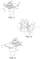
- Figure 3 shows a rotary machine axis assembly of a machine tool according to an example of the present disclosure.
- a linear positioning mechanism 40 is included.
- the linear positioning mechanism is carried by the linear machine axis 8 and the linear positioning mechanism in turn carries the rotary positioning mechanism 30.
- the linear positioning mechanism includes a slideable support and a linear positioning mechanism base.
- the slideable support is slideable relative to the linear positioning mechanism base along a linear slide reference axis that is parallel to the linear drive reference axis 18. Addition of the linear positioning mechanism further extends the workzone of the machine tool. It allows the slideable support to be translated between two or more indexed locations along reference axis 18.
- the slideable support may be fixed, clamped or locked in a selected position relative to its base using a locking mechanism (not shown in the drawing).
- the linear positioning mechanism has been used to displace the drive spindle 6 in the direction of reference axis 18.
- the drive spindle has been rotated relative to the linear machine axis using the rotary positioning mechanism through an angle of more than 90° to facilitate the desired access to the surface to be machined by the grinding wheel 12.
- Positional control of a rotary positioning mechanism and/or a linear positioning mechanism as described herein can be achieved by a control arrangement of a machine tool with reference to calibration methods or by direct measurement using additional position transducers or encoders.
- Figure 6 shows a thin ring bearing which is an example of a workpiece having surfaces which may be machined using a machine tool according to examples described herein.
- the outer diameter 50 of the outer race needs to be machined to precisely fit to the inside diameter of a supporting assembly.
- the inner diameter 54 of the outer race is machined to be concentric to the outer diameter 50 and profiled to provide a track for the bearings 56 held in a bearing cage 58.
- the outer diameter 60 of the inner race 62 is similarly profiled to provide a track for the bearings.
- the inner diameter 64 of the inner race should be machined to precisely fit the shaft of a supporting assembly.
- the workpiece is a bearing raceway 70 by way of example.
- the raceway is mounted on the drive spindle 6 with its central axis coaxial with the spindle reference axis 34.
- the spindle reference axis is perpendicular to the linear drive reference axis 18.
- the second rotary machine axis 16 carries four tool spindles 14 at equally spaced locations around its reference axis 22.
- a grinding wheel 12 is in contact with an outer diameter 50 of the bearing raceway 70.
- the outer diameter 50 of the raceway 70 is fed into the grinding wheel using the linear machine axis whilst holding the first and second rotary machine axes 10, 16 stationary.
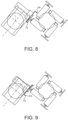
- Figure 8 shows displacement of the drive spindle 6 relative to the linear machine axis 8 by a linear positioning mechanism (not shown) carried by the linear machine axis.
- the machine axes are operable to move the grinding wheel out of contact with the outer diameter of the bearing raceway 70 and into contact with its inner diameter 54 as shown in Figure 8 .
- the inner diameter may be plunge ground by feeding the inner diameter towards the grinding wheel using the linear machine axis.
- Figure 9 shows an alternative configuration in which the inner diameter 54 of the raceway 70 is ground using a smaller displacement of the drive spindle from the position shown in Figure 7 . It may be preferable to reverse the direction of rotation of the workpiece and/or the tool spindle to optimise consistency of grinding forces and location of the workpiece.
- Figure 10 illustrates how a grinding wheel 12 can be translated across the surface of a workpiece 70 in a direction parallel to the spindle reference axis 34 using the two rotary and one linear machine axes simultaneously. Combining motion of the linear machine axis in direction A with rotation of the rotary machine axes in the respective directions B and C allows the grinding wheel to be translated across the outer diameter 50 of the bearing raceway 70.
- references herein to perpendicular or parallel relative orientations and the like may be interpreted as defining orthogonal or parallel relationships between components within practical tolerances.
- machine axis denotes a driven physical machine axis, as opposed to a reference axis. Each machine axis has two portions which are machine-driven relative to each other, about or along a reference axis.
- a machine axis may be servo-driven under the control of a control arrangement of the machine tool and may include guideways using hydrostatic or rolling element bearings.
- the machine axes or rotary or linear positioning mechanisms referred to may provide the only degrees of freedom of the machine tools.
Landscapes
- Engineering & Computer Science (AREA)
- Mechanical Engineering (AREA)
- Machine Tool Units (AREA)
- Constituent Portions Of Griding Lathes, Driving, Sensing And Control (AREA)
- Grinding And Polishing Of Tertiary Curved Surfaces And Surfaces With Complex Shapes (AREA)
Applications Claiming Priority (3)
| Application Number | Priority Date | Filing Date | Title |
|---|---|---|---|
| GB1918112.2A GB2589874B (en) | 2019-12-10 | 2019-12-10 | Machine tools and methods of operation thereof |
| PCT/GB2020/053138 WO2021116668A1 (en) | 2019-12-10 | 2020-12-08 | Machine tools and methods of operation thereof |
| EP20825221.3A EP4072773B1 (de) | 2019-12-10 | 2020-12-08 | Werkzeugmaschine und verfahren damit |
Related Parent Applications (2)
| Application Number | Title | Priority Date | Filing Date |
|---|---|---|---|
| EP20825221.3A Division-Into EP4072773B1 (de) | 2019-12-10 | 2020-12-08 | Werkzeugmaschine und verfahren damit |
| EP20825221.3A Division EP4072773B1 (de) | 2019-12-10 | 2020-12-08 | Werkzeugmaschine und verfahren damit |
Publications (2)
| Publication Number | Publication Date |
|---|---|
| EP4464456A2 true EP4464456A2 (de) | 2024-11-20 |
| EP4464456A3 EP4464456A3 (de) | 2025-05-14 |
Family
ID=69172125
Family Applications (2)
| Application Number | Title | Priority Date | Filing Date |
|---|---|---|---|
| EP24205195.1A Pending EP4464456A3 (de) | 2019-12-10 | 2020-12-08 | Werkzeugmaschinen und verfahren zum betrieb davon |
| EP20825221.3A Active EP4072773B1 (de) | 2019-12-10 | 2020-12-08 | Werkzeugmaschine und verfahren damit |
Family Applications After (1)
| Application Number | Title | Priority Date | Filing Date |
|---|---|---|---|
| EP20825221.3A Active EP4072773B1 (de) | 2019-12-10 | 2020-12-08 | Werkzeugmaschine und verfahren damit |
Country Status (9)
| Country | Link |
|---|---|
| US (1) | US20230311256A1 (de) |
| EP (2) | EP4464456A3 (de) |
| JP (1) | JP2023506437A (de) |
| CN (1) | CN114867580B (de) |
| CA (1) | CA3158838A1 (de) |
| ES (1) | ES3013286T3 (de) |
| GB (1) | GB2589874B (de) |
| MX (1) | MX2022006957A (de) |
| WO (1) | WO2021116668A1 (de) |
Families Citing this family (1)
| Publication number | Priority date | Publication date | Assignee | Title |
|---|---|---|---|---|
| GB2613826A (en) * | 2021-12-16 | 2023-06-21 | Fives Landis Ltd | A machine tool for machining workpieces and methods of operation thereof |
Citations (2)
| Publication number | Priority date | Publication date | Assignee | Title |
|---|---|---|---|---|
| GB2456843A (en) | 2008-01-25 | 2009-07-29 | Cinetic Landis Ltd | Machine tools and Methods of operation thereof |
| GB2476468A (en) | 2009-12-22 | 2011-06-29 | Cinetic Landis Ltd | Machine tool and method of operation thereof |
Family Cites Families (26)
| Publication number | Priority date | Publication date | Assignee | Title |
|---|---|---|---|---|
| US2718820A (en) * | 1952-07-31 | 1955-09-27 | Faselt Fritz | Spindle attachment for machine tools |
| US3380322A (en) * | 1966-02-04 | 1968-04-30 | Optomechanisms Inc | Angular work indexing table |
| US3572680A (en) * | 1968-03-28 | 1971-03-30 | Frederick R Neff | Machine tool table |
| JPS609602A (ja) * | 1983-06-30 | 1985-01-18 | Mitsubishi Heavy Ind Ltd | 複合加工用アタツチメント |
| DE3729162A1 (de) * | 1987-09-01 | 1989-03-09 | Guehring Automation | Werkzeugmaschine zur bearbeitung von werkstuecken mittels rundlaufender werkzeuge |
| US5231587A (en) * | 1990-07-12 | 1993-07-27 | Loh Optical Machinery, Inc. | Computer controlled lens surfacer |
| US5429345A (en) * | 1993-05-27 | 1995-07-04 | Yang; Tai-Her | Rotary disc positioner with axial displacement |
| JPH07276165A (ja) * | 1994-04-04 | 1995-10-24 | Tai-Her Yang | 多軸心重なり面で各角転位が工作物の工作面の駆動の標準点の座標転位駆動を可能にする工作物支持方法 |
| JPH0810997A (ja) * | 1994-06-29 | 1996-01-16 | Misawa Ceramics Kk | プレス装置 |
| JPH10286687A (ja) * | 1997-04-11 | 1998-10-27 | Toyota Motor Corp | レーザ加工装置およびレーザ加工方法 |
| JP4322324B2 (ja) * | 1997-04-17 | 2009-08-26 | ノバルティス アクチエンゲゼルシャフト | 旋盤装置及び方法 |
| JP2000308959A (ja) * | 1999-04-27 | 2000-11-07 | Olympus Optical Co Ltd | 研磨方法 |
| JP2001087901A (ja) * | 1999-09-27 | 2001-04-03 | Okuma Corp | 複合加工nc旋盤 |
| JP2003245833A (ja) * | 2002-02-21 | 2003-09-02 | Honda Motor Co Ltd | 直動案内装置 |
| US6585463B1 (en) * | 2002-05-23 | 2003-07-01 | Barnes Group Inc. | Milling apparatus |
| DE10256222B4 (de) * | 2002-12-02 | 2005-05-12 | Klingelnberg Gmbh | Maschine und Verfahren mit 7 Achsen zum CNC-gesteuerten spanabhebenden Bearbeiten, insbesondere Wälzfräsen oder Wälzschleifen, von Spiralkegelrädern |
| DE102005011306A1 (de) * | 2005-03-07 | 2006-09-14 | Traub Drehmaschinen Gmbh & Co. Kg | Werkzeugmaschine |
| DE102005021640B4 (de) * | 2005-05-06 | 2007-08-09 | Satisloh Gmbh | Maschine zur Bearbeitung von optischen Werkstücken, insbesondere von Kunststoff-Brillengläsern |
| JP2007229892A (ja) * | 2006-03-03 | 2007-09-13 | Honda Motor Co Ltd | ワーク位置決めテーブル |
| GB2491020B (en) * | 2012-05-15 | 2013-03-27 | Cinetic Landis Ltd | Machine tool with central support between machine axes |
| KR20160032135A (ko) * | 2013-08-01 | 2016-03-23 | 그롭-베르케 게엠베하 운트 코. 카게 | 선회 가능한 공구 스핀들을 포함하는 공작 기계 |
| DE102013013276A1 (de) * | 2013-08-08 | 2015-02-12 | Liebherr-Verzahntechnik Gmbh | Werkzeugmaschine und Verfahren zur spanenden Bearbeitung von Werkstücken mit mindestens zwei separaten Bearbeitungseinheiten |
| DE102015218206A1 (de) * | 2015-09-22 | 2017-03-23 | Deckel Maho Pfronten Gmbh | Werkzeugmaschine, insbesondere mehrfachspindel-fräsmaschine |
| FR3054158B1 (fr) * | 2016-07-21 | 2019-06-28 | Comau France | Machine-outil d’usinage |
| DE202017106229U1 (de) * | 2017-10-13 | 2019-01-16 | Thorsten Lasch | Bearbeitungsvorrichtung |
| GB2578143B (en) * | 2018-10-18 | 2023-02-15 | Fives Landis Ltd | Machine tools and calibration thereof |
-
2019
- 2019-12-10 GB GB1918112.2A patent/GB2589874B/en active Active
-
2020
- 2020-12-08 CN CN202080085854.8A patent/CN114867580B/zh active Active
- 2020-12-08 CA CA3158838A patent/CA3158838A1/en active Pending
- 2020-12-08 MX MX2022006957A patent/MX2022006957A/es unknown
- 2020-12-08 WO PCT/GB2020/053138 patent/WO2021116668A1/en not_active Ceased
- 2020-12-08 JP JP2022535191A patent/JP2023506437A/ja active Pending
- 2020-12-08 EP EP24205195.1A patent/EP4464456A3/de active Pending
- 2020-12-08 ES ES20825221T patent/ES3013286T3/es active Active
- 2020-12-08 US US17/780,663 patent/US20230311256A1/en not_active Abandoned
- 2020-12-08 EP EP20825221.3A patent/EP4072773B1/de active Active
Patent Citations (3)
| Publication number | Priority date | Publication date | Assignee | Title |
|---|---|---|---|---|
| GB2456843A (en) | 2008-01-25 | 2009-07-29 | Cinetic Landis Ltd | Machine tools and Methods of operation thereof |
| GB2476468A (en) | 2009-12-22 | 2011-06-29 | Cinetic Landis Ltd | Machine tool and method of operation thereof |
| EP2684640A2 (de) | 2009-12-22 | 2014-01-15 | Cinetic Landis Limited | Werkzeugmaschine und Verfahren unter Verwendung einer solchen Maschine |
Also Published As
| Publication number | Publication date |
|---|---|
| EP4072773A1 (de) | 2022-10-19 |
| CA3158838A1 (en) | 2021-06-17 |
| EP4072773B1 (de) | 2025-01-08 |
| GB2589874A (en) | 2021-06-16 |
| JP2023506437A (ja) | 2023-02-16 |
| CN114867580B (zh) | 2024-10-29 |
| EP4464456A3 (de) | 2025-05-14 |
| CN114867580A (zh) | 2022-08-05 |
| US20230311256A1 (en) | 2023-10-05 |
| WO2021116668A1 (en) | 2021-06-17 |
| GB201918112D0 (en) | 2020-01-22 |
| EP4072773C0 (de) | 2025-01-08 |
| MX2022006957A (es) | 2022-07-12 |
| GB2589874B (en) | 2024-05-01 |
| ES3013286T3 (en) | 2025-04-11 |
Similar Documents
| Publication | Publication Date | Title |
|---|---|---|
| CN100506480C (zh) | 带有同心度修正的研磨机 | |
| WO2000051779A2 (en) | Machine tool | |
| JP2001513705A (ja) | 工作物クランプテーブル | |
| EP4072773B1 (de) | Werkzeugmaschine und verfahren damit | |
| JP2002509489A (ja) | 塊状ブロックとスライド式コラムを有する工作機械装置及び本装置を組み込んだ機械 | |
| JP7741573B2 (ja) | 物体に対する複数の製造作業を実施するための方法および装置 | |
| CN111844070B (zh) | 一种面向深孔原位加工作业的移动式混联机器人 | |
| JP2006062077A (ja) | 加工物のプロファイルの研削方法及び研削装置 | |
| JPS641242B2 (de) | ||
| EP3603860B1 (de) | 5-achsen-bearbeitungszentrum | |
| KR102893986B1 (ko) | 원형회전타입 멀티가공 공정시스템 | |
| KR20240166191A (ko) | 멀티가공용 원형회전복합가공장치 | |
| US12202095B2 (en) | Modular clamping device | |
| CN111844071B (zh) | 一种移动式深孔原位加工机器人 | |
| JPH0724999B2 (ja) | 工作物回転型複合工作機械 | |
| JP3395701B2 (ja) | 加工機 | |
| JPS63216651A (ja) | 機械加工方法 | |
| KR102922837B1 (ko) | 소재의 크기에 가변적으로 오토포커싱 가능한 피가공물 고정용 지그장치 | |
| EP2490857B1 (de) | Vertikale drehbank mit verbesserter aufnahme | |
| CN108972107B (zh) | 一种机床 | |
| WO2024105373A1 (en) | Machine tools for machining a workpiece and methods of operation thereof | |
| JP4006253B2 (ja) | 加工セル装置 | |
| CN117920820A (zh) | 滚压机床 | |
| CN119567029A (zh) | 用于加工球头外球面结构的多通道数控磨削机床 | |
| JPH0192004A (ja) | リードカム加工機 |
Legal Events
| Date | Code | Title | Description |
|---|---|---|---|
| PUAI | Public reference made under article 153(3) epc to a published international application that has entered the european phase |
Free format text: ORIGINAL CODE: 0009012 |
|
| STAA | Information on the status of an ep patent application or granted ep patent |
Free format text: STATUS: REQUEST FOR EXAMINATION WAS MADE |
|
| 17P | Request for examination filed |
Effective date: 20241008 |
|
| AC | Divisional application: reference to earlier application |
Ref document number: 4072773 Country of ref document: EP Kind code of ref document: P |
|
| AK | Designated contracting states |
Kind code of ref document: A2 Designated state(s): AL AT BE BG CH CY CZ DE DK EE ES FI FR GB GR HR HU IE IS IT LI LT LU LV MC MK MT NL NO PL PT RO RS SE SI SK SM TR |
|
| RIC1 | Information provided on ipc code assigned before grant |
Ipc: B23Q 1/50 20060101ALI20250114BHEP Ipc: B23Q 1/48 20060101AFI20250114BHEP |
|
| PUAL | Search report despatched |
Free format text: ORIGINAL CODE: 0009013 |
|
| AK | Designated contracting states |
Kind code of ref document: A3 Designated state(s): AL AT BE BG CH CY CZ DE DK EE ES FI FR GB GR HR HU IE IS IT LI LT LU LV MC MK MT NL NO PL PT RO RS SE SI SK SM TR |
|
| RIC1 | Information provided on ipc code assigned before grant |
Ipc: B23Q 1/50 20060101ALI20250407BHEP Ipc: B23Q 1/48 20060101AFI20250407BHEP |
|
| STAA | Information on the status of an ep patent application or granted ep patent |
Free format text: STATUS: EXAMINATION IS IN PROGRESS |
|
| 17Q | First examination report despatched |
Effective date: 20260304 |