EP4464469A2 - Commande de changement d'outil de véhicule télécommandé submersible - Google Patents
Commande de changement d'outil de véhicule télécommandé submersible Download PDFInfo
- Publication number
- EP4464469A2 EP4464469A2 EP24205154.8A EP24205154A EP4464469A2 EP 4464469 A2 EP4464469 A2 EP 4464469A2 EP 24205154 A EP24205154 A EP 24205154A EP 4464469 A2 EP4464469 A2 EP 4464469A2
- Authority
- EP
- European Patent Office
- Prior art keywords
- arm
- tool
- rov
- tool holder
- submersible
- Prior art date
- Legal status (The legal status is an assumption and is not a legal conclusion. Google has not performed a legal analysis and makes no representation as to the accuracy of the status listed.)
- Pending
Links
Images



Classifications
-
- E—FIXED CONSTRUCTIONS
- E21—EARTH OR ROCK DRILLING; MINING
- E21B—EARTH OR ROCK DRILLING; OBTAINING OIL, GAS, WATER, SOLUBLE OR MELTABLE MATERIALS OR A SLURRY OF MINERALS FROM WELLS
- E21B41/00—Equipment or details not covered by groups E21B15/00 - E21B40/00
- E21B41/04—Manipulators for underwater operations, e.g. temporarily connected to well heads
-
- B—PERFORMING OPERATIONS; TRANSPORTING
- B63—SHIPS OR OTHER WATERBORNE VESSELS; RELATED EQUIPMENT
- B63G—OFFENSIVE OR DEFENSIVE ARRANGEMENTS ON VESSELS; MINE-LAYING; MINE-SWEEPING; SUBMARINES; AIRCRAFT CARRIERS
- B63G8/00—Underwater vessels, e.g. submarines; Equipment specially adapted therefor
- B63G8/001—Underwater vessels adapted for special purposes, e.g. unmanned underwater vessels; Equipment specially adapted therefor, e.g. docking stations
-
- B—PERFORMING OPERATIONS; TRANSPORTING
- B25—HAND TOOLS; PORTABLE POWER-DRIVEN TOOLS; MANIPULATORS
- B25J—MANIPULATORS; CHAMBERS PROVIDED WITH MANIPULATION DEVICES
- B25J13/00—Controls for manipulators
- B25J13/08—Controls for manipulators by means of sensing devices, e.g. viewing or touching devices
-
- B—PERFORMING OPERATIONS; TRANSPORTING
- B25—HAND TOOLS; PORTABLE POWER-DRIVEN TOOLS; MANIPULATORS
- B25J—MANIPULATORS; CHAMBERS PROVIDED WITH MANIPULATION DEVICES
- B25J13/00—Controls for manipulators
- B25J13/08—Controls for manipulators by means of sensing devices, e.g. viewing or touching devices
- B25J13/085—Force or torque sensors
-
- B—PERFORMING OPERATIONS; TRANSPORTING
- B25—HAND TOOLS; PORTABLE POWER-DRIVEN TOOLS; MANIPULATORS
- B25J—MANIPULATORS; CHAMBERS PROVIDED WITH MANIPULATION DEVICES
- B25J15/00—Gripping heads and other end effectors
- B25J15/04—Gripping heads and other end effectors with provision for the remote detachment or exchange of the head or parts thereof
-
- B—PERFORMING OPERATIONS; TRANSPORTING
- B25—HAND TOOLS; PORTABLE POWER-DRIVEN TOOLS; MANIPULATORS
- B25J—MANIPULATORS; CHAMBERS PROVIDED WITH MANIPULATION DEVICES
- B25J15/00—Gripping heads and other end effectors
- B25J15/04—Gripping heads and other end effectors with provision for the remote detachment or exchange of the head or parts thereof
- B25J15/0491—Gripping heads and other end effectors with provision for the remote detachment or exchange of the head or parts thereof comprising end-effector racks
-
- B—PERFORMING OPERATIONS; TRANSPORTING
- B25—HAND TOOLS; PORTABLE POWER-DRIVEN TOOLS; MANIPULATORS
- B25J—MANIPULATORS; CHAMBERS PROVIDED WITH MANIPULATION DEVICES
- B25J9/00—Program-controlled manipulators
- B25J9/16—Program controls
-
- B—PERFORMING OPERATIONS; TRANSPORTING
- B25—HAND TOOLS; PORTABLE POWER-DRIVEN TOOLS; MANIPULATORS
- B25J—MANIPULATORS; CHAMBERS PROVIDED WITH MANIPULATION DEVICES
- B25J9/00—Program-controlled manipulators
- B25J9/16—Program controls
- B25J9/1628—Program controls characterised by the control loop
- B25J9/1633—Program controls characterised by the control loop compliant, force, torque control, e.g. combined with position control
-
- B—PERFORMING OPERATIONS; TRANSPORTING
- B25—HAND TOOLS; PORTABLE POWER-DRIVEN TOOLS; MANIPULATORS
- B25J—MANIPULATORS; CHAMBERS PROVIDED WITH MANIPULATION DEVICES
- B25J9/00—Program-controlled manipulators
- B25J9/16—Program controls
- B25J9/1656—Program controls characterised by programming, planning systems for manipulators
- B25J9/1664—Program controls characterised by programming, planning systems for manipulators characterised by motion, path, trajectory planning
-
- B—PERFORMING OPERATIONS; TRANSPORTING
- B25—HAND TOOLS; PORTABLE POWER-DRIVEN TOOLS; MANIPULATORS
- B25J—MANIPULATORS; CHAMBERS PROVIDED WITH MANIPULATION DEVICES
- B25J9/00—Program-controlled manipulators
- B25J9/16—Program controls
- B25J9/1679—Program controls characterised by the tasks executed
- B25J9/1689—Teleoperation
-
- B—PERFORMING OPERATIONS; TRANSPORTING
- B63—SHIPS OR OTHER WATERBORNE VESSELS; RELATED EQUIPMENT
- B63C—LAUNCHING, HAULING-OUT, OR DRY-DOCKING OF VESSELS; LIFE-SAVING IN WATER; EQUIPMENT FOR DWELLING OR WORKING UNDER WATER; MEANS FOR SALVAGING OR SEARCHING FOR UNDERWATER OBJECTS
- B63C11/00—Equipment for dwelling or working underwater; Means for searching for underwater objects
- B63C11/52—Tools specially adapted for working underwater, not otherwise provided for
-
- B—PERFORMING OPERATIONS; TRANSPORTING
- B63—SHIPS OR OTHER WATERBORNE VESSELS; RELATED EQUIPMENT
- B63G—OFFENSIVE OR DEFENSIVE ARRANGEMENTS ON VESSELS; MINE-LAYING; MINE-SWEEPING; SUBMARINES; AIRCRAFT CARRIERS
- B63G8/00—Underwater vessels, e.g. submarines; Equipment specially adapted therefor
- B63G8/001—Underwater vessels adapted for special purposes, e.g. unmanned underwater vessels; Equipment specially adapted therefor, e.g. docking stations
- B63G2008/002—Underwater vessels adapted for special purposes, e.g. unmanned underwater vessels; Equipment specially adapted therefor, e.g. docking stations unmanned
-
- B—PERFORMING OPERATIONS; TRANSPORTING
- B63—SHIPS OR OTHER WATERBORNE VESSELS; RELATED EQUIPMENT
- B63G—OFFENSIVE OR DEFENSIVE ARRANGEMENTS ON VESSELS; MINE-LAYING; MINE-SWEEPING; SUBMARINES; AIRCRAFT CARRIERS
- B63G8/00—Underwater vessels, e.g. submarines; Equipment specially adapted therefor
- B63G8/001—Underwater vessels adapted for special purposes, e.g. unmanned underwater vessels; Equipment specially adapted therefor, e.g. docking stations
- B63G2008/002—Underwater vessels adapted for special purposes, e.g. unmanned underwater vessels; Equipment specially adapted therefor, e.g. docking stations unmanned
- B63G2008/005—Underwater vessels adapted for special purposes, e.g. unmanned underwater vessels; Equipment specially adapted therefor, e.g. docking stations unmanned remotely controlled
-
- B—PERFORMING OPERATIONS; TRANSPORTING
- B63—SHIPS OR OTHER WATERBORNE VESSELS; RELATED EQUIPMENT
- B63G—OFFENSIVE OR DEFENSIVE ARRANGEMENTS ON VESSELS; MINE-LAYING; MINE-SWEEPING; SUBMARINES; AIRCRAFT CARRIERS
- B63G8/00—Underwater vessels, e.g. submarines; Equipment specially adapted therefor
- B63G8/001—Underwater vessels adapted for special purposes, e.g. unmanned underwater vessels; Equipment specially adapted therefor, e.g. docking stations
- B63G2008/002—Underwater vessels adapted for special purposes, e.g. unmanned underwater vessels; Equipment specially adapted therefor, e.g. docking stations unmanned
- B63G2008/005—Underwater vessels adapted for special purposes, e.g. unmanned underwater vessels; Equipment specially adapted therefor, e.g. docking stations unmanned remotely controlled
- B63G2008/007—Underwater vessels adapted for special purposes, e.g. unmanned underwater vessels; Equipment specially adapted therefor, e.g. docking stations unmanned remotely controlled by means of a physical link to a base, e.g. wire, cable or umbilical
-
- G—PHYSICS
- G05—CONTROLLING; REGULATING
- G05B—CONTROL OR REGULATING SYSTEMS IN GENERAL; FUNCTIONAL ELEMENTS OF SUCH SYSTEMS; MONITORING OR TESTING ARRANGEMENTS FOR SUCH SYSTEMS OR ELEMENTS
- G05B2219/00—Program-control systems
- G05B2219/30—Nc systems
- G05B2219/40—Robotics, robotics mapping to robotics vision
- G05B2219/40184—Compliant teleoperation, operator controls motion, system controls contact, force
-
- G—PHYSICS
- G05—CONTROLLING; REGULATING
- G05B—CONTROL OR REGULATING SYSTEMS IN GENERAL; FUNCTIONAL ELEMENTS OF SUCH SYSTEMS; MONITORING OR TESTING ARRANGEMENTS FOR SUCH SYSTEMS OR ELEMENTS
- G05B2219/00—Program-control systems
- G05B2219/30—Nc systems
- G05B2219/40—Robotics, robotics mapping to robotics vision
- G05B2219/40271—Underwater, submarine movable manipulator
Definitions
- ROV submersible remote operated vehicle
- FIG. 1 shows an example submersible remote operated vehicle (ROV) 10 operating subsea.
- the ROV 10 can be controlled by a human operator from a control interface 12, typically on a vessel 30 (e.g., a platform, ship or other vessel) above a surface 14 of a body of water, to fly through the water and perform certain operations.
- the ROV 10 of FIG. 1 includes a manipulator arm 16 with a tool 18 attached to its end.
- the ROV 10 can include one or more additional arms, such as a grabber or other type of arm, but the manipulator arm 16 is the most dexterous, having multiple pivot and rotational joints 22 that enable movement of the arm in multiple degrees of freedom.
- each joint 22 in the manipulator arm 16 collectively provide 6 degrees of freedom (i.e., movement along the X-axis, Y-axis, Z-axis, roll, pitch, and yaw).
- Each joint 22 includes a mechanical joint that enables movement between the connected segments of the arm 16, one or more actuators to drive movement of the joint and, in certain instances, one or more sensors, such as position and force (linear and/or torque) sensors.
- the control interface 12 is communicably coupled to the ROV 10 submerged in the water.
- the ROV 10 is connected to the control interface 12 through a tether management system (TMS) 24, also submerged in the water, and supported from the vessel 30.
- TMS tether management system
- the operator controls the ROV 10 to fly around and perform operations and the TMS 24, in performing those operations, via the control interface 12.
- An umbilical 26 extends between the control interface 12 at the vessel 30 to the TMS 24.
- the TMS 24 pays out and takes up a tether 28 that extends between the TMS 24 and the ROV 10.
- the umbilical 26 and tether 28 communicate power, e.g., electrical power, and data between the control interface 12 and the TMS 24 and ROV 10.
- the data communicated on the umbilical 26 and tether 28 includes control signals to actuators of the TMS 24 and ROV 10 and other control communications, output from sensors at the TMS 24 and ROV 10, and other data.
- the ROV 10 in turn, supplies power, e.g., electrical and/or hydraulic power, and exchanges data with the tool 18 through the manipulator arm 16, enabling the operator to actuate and operate the tool 18 via the control interface 12.
- the tool 18 and ROV 10 communicate data including control signals to actuators in the tool 18, output from sensors in the tool 18, and other data, via the manipulator arm 16, which, in turn, can be communicated with the control interface 12.
- FIG. 1 shows the tool 18 as a jaws with two parts that can be operated to open and close to grasp and hold objects.
- a tool interchange 20 mounts at the end of the manipulator arm 16, between the manipulator arm 16 and the tool 18, becoming the interface between the arm 16 and the tool 18.
- the tool interchange 20 enables the ROV 10 to change out tools 18 while subsea with no outside assistance. While there are many examples of tool interchange 20 that could be used herein, co-pending US Application 16/376,622, filed April 5, 2019 and entitled “Submersible Remote Operated Vehicle Tool Interchange,” shows an example tool interchange 20 that can be used herein.
- the operator can operate the manipulator arm 16 to dock into a tool holder of a tool storage unit 32.
- the operator can then actuate the tool interchange 20 to release the tool from the manipulator arm 16, withdraw the manipulator arm 16 from the tool holder of the tool storage unit 32 and leave the tool 18 in the tool storage unit - in other words, stow the tool 18.
- the operator can then operate the manipulator arm 16 to dock in a different tool holder storing a different tool 18, and actuate the tool interchange 20 to lock to and establish data and power communications with the different tool 18 - in other words, connect to a tool 18. Thereafter, the operator can withdraw the manipulator arm 16 from the tool holder and use the different tool 18 in performing operations.
- the tool storage unit 32 may be on the ROV 10, on the TMS 24, in both locations and/or elsewhere.
- the tool storage unit 32 may be a fixed tool storage unit (i.e., with one or more tool holders fixed in position) or a changeable type (i.e., with multiple tool holders, each moveable to be selectively presented for connecting to or stowing a tool).
- the operator can use the control interface 12 to select a particular tool or tool holder from a menu, and the tool storage unit 32 will operate to move the tool holders to present the tool holder to allow the manipulator arm 16 to connect to or stow a tool.
- the tool storage unit 32 is a carousel type, where the tool holders are arranged on a disk that rotates on its central axis to selectively align the tool holders to be presented.
- FIG. 2 is a perspective view of an example tool holder 200 that can be used in the tool storage unit 32 described above.
- the example tool holder 200 is shown with a docked manipulator arm, and more specifically, shown receiving a tool 18 locked to a tool interchange 20.
- the remainder of the manipulator arm 16 has been omitted for clarity of illustration, but would extend outward from the back of the tool interchange 20 (similar to that shown in FIG. 1 ).
- the tool holder 200 includes a housing 202, shown here as a frame, with a face plate 204.
- the housing 202 defines a receptacle 206 that receives and holds the tool 18, so that the tool can be stored when not in use.
- the face plate 204 has an opening 208 sized to pass the tool 18.
- a plurality of lead-in ramps 210 are positioned surrounding the opening 208.
- FIG. 3A three lead-in ramps 210 are shown, equally distributed around the opening 208, but fewer or additional lead-in ramps 210 could be provided.
- FIG. 2 shows the lead-in ramps 210 formed on a common ring affixed to the front surface of the face plate 204, while FIG. 3A shows discrete lead-in ramps 210, separately affixed to the front surface of the plate 204.
- the lead-in ramps 210 each have a ramped inward facing surface 212, and the surfaces 212 of the lead-in ramps 210 cooperate with one another to define a generally conical guide, decreasing in diameter toward the opening 208. Accordingly, the lead-in ramps 210 are able to contact the outer periphery of a tool 18 received at the mouth of the lead-in ramps 210 and guide the tool 18 in position and orientation toward and through the opening 208 and into the receptacle 206 as the tool 18 is moved toward and into the receptacle 206.
- the face plate 204 also includes features to lock the tool in place.
- the features can be provided on the lead-in ramps 210 (or the ring at the base of the lead-in ramps 210 as in FIG. 2 ) in the form of a twist-lock keyway 224 that engages corresponding key 226 on the periphery of the tool 18.
- the keys 226 of the tool 18 are received in the keyways 224, and the tool 18 rotated (clockwise in FIG. 3B )
- the keys 226 lock into the keyways 224, eventually bottom out at the end of the keyways 224, and signal to the ROV or operator that the tool 18 is fully received, locked and rotationally aligned in the tool holder 200.
- the key/keyways also axially align and support the tool 18 in the tool holder 200.
- the key/keyways can be reversed, having keys carried on the face plate 204 and a keyway on the tool 18.
- the face plate 204 also has a visual tag 214 that includes an alignment fiducial 216 and a tool location identification marking 218.
- the alignment fiducial 216 can be embedded within the tool location marking 218 as shown, or it can be separate from the tool location identification marking 218.
- the alignment fiducial 216 is in a specified position and orientation relative to the opening 208 and receptacle 206 of the tool holder 200, so that it can be used (as discussed below) in guiding the manipulator arm to dock.
- the alignment fiducial 216 is of a type for 2D position location.
- the tool location marking 218 can include a human readable marking identifying the tool 18 specified to be stored in the associated receptacle 206 and/or a machine readable marking, like a barcode, quick response "QR" code, or another type of machine readable marking, identifying the tool location.
- a camera 220 is carried on the manipulator arm, shown in FIG. 2 as being mounted directly to the tool interchange 20 (that, in turn, is mounted directly to the manipulator arm).
- the camera 220 could be mounted directly to the arm itself or to another component carried by the arm to enable the camera 220 clear sight of the visual tag 214 as the tool 18 is being docked.
- the camera 220 can be carried by the tool storage unit or something else (e.g., the TMS or other device carrying the tool storage unit).
- the camera 220 might be mounted remote from the ROV.
- FIG. 3B shows the tool 18 as it would be positioned when stowed in the tool holder 200, but with the remainder of the tool holder 200 omitted for clarity of illustration.
- a male mount 222 of the tool 18 protrudes through the opening 208 of the face plate 204.
- the male mount 222 is received in a corresponding receptacle of the tool interchange 20 on the manipulator arm 16, and the tool interchange 20 grips the male mount 222 to lock the tool 18 to the manipulator arm 16.
- the male mount 222 includes alignment features to center the tool interchange 20 to the tool 18 and rotationally align the tool interchange 20 to the tool 18.
- the male mount 222 is generally frusta-conical which centers in a corresponding frusta-conical shape of the tool interchange 20 to center the tool 18 to the tool interchange 20, and position the tool 18 in a specified location relative to the manipulator arm 16.
- Rotational alignment for example, can be achieved by a key and keyway on the male mount 222 and tool interchange, in certain instances.
- the concepts herein encompass a system for control of the TMS 24 and ROV 10 (including the manipulator arm 16 and tool 18) by computer, having a processor 402 with memory 404, that receives input from sensors 414 of the TMS and/or the ROV and signals actuators 416 that operate the TMS 24 and/or the ROV 10.
- the memory 404 stores instructions that cause the processor 402 to perform the operations described herein.
- the actuators 416 include actuators at each of the joints (e.g., joints 22, FIG. 1 ) that move the joints in moving the manipulator arm, as well as other actuators.
- the sensors 414 include one or more position sensors, force sensors (linear and/or torque), the camera (e.g., camera 220), as well as other sensors.
- the sensors include a sensor in the manipulator arm, near the tool interface, capable of sensing force and/or torques in 6 degrees of freedom.
- the sensors include a force (liner and/or torque), pressure and/or position sensor at each of the joints (e.g., joints 22) of the manipulator arm.
- the processor 402 could be a single processor or multiple processors in communication with each other, and the memory 404 could be a single memory or multiple memories in communication with each other.
- FIG. 4 schematically shows an example of the control interface 12, and for convenience of reference, processor 402 and memory 404 are depicted within a housing 406 of the interface 12. Although shown as all within the housing 406, processor 402 could be distributed, with aspects remote from the housing 406.
- the memory 404 could be embedded in a processor.
- the memory 404 is depicted as one memory, it could be multiple memories all within the housing 406 or with one or more of the memories distributed, remote from the housing 406.
- the processor 402 is a system of processors distributed in the manipulator arm, ROV and/or housing 406 each with associated (embedded or separate) memory. The processor 402 and memory 404 are in communication with the sensors of the system.
- the control interface 12 includes a display 408 and a user input 410 through which the human operator interfaces with the control interface 12.
- the display 408 can include one or multiple screens, goggles and/or other types of displays.
- the user input 410 can include one or multiple types of user input, such as keyboards, hand controllers, physical buttons and switches and/or other types of user inputs.
- the control interface 12 can present the human operator with information about the operation of the ROV, TMS and the environment, as well as menus of options for controlling the system, such as soft menus 412 as depicted in FIG. 4 displayed via the display 408.
- the human operator commands operation of the ROV 10, including the manipulator arm 16 and any connected tool 18, and the TMS 24 via the control interface 12.
- the operator can effectuate docking the arm 16 to a tool holder, such as tool holder 200 ( FIG. 2 ), of a tool storage unit 32.
- the system described herein automates the docking, which can be activated via the control interface 12 (e.g., via a menu 412, the input 410 and/or other manner).
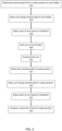
- FIG. 5 is a flow chart of example method steps in automated docking of the manipulator arm (with or without an attached tool) to a tool holder.
- the operator operates the arm to an initial or ready position in proximity to the tool holder. For example, when the tool holder is apart from the ROV, the operator flys the ROV to the tool holder and operates the arm to a position near the tool holder. When the tool holder is on the ROV, the operator positions the arm so it is free of external obstructions and able to move to the tool holder.
- the automated docking sequence is initiated, at operation 502, by determining a nominal path between the current or ready position and orientation of the arm and a docked position and orientation with the arm docked to the tool holder.
- the system receives and logs input from sensors in the arm and thus knows the current position and orientation of the tool, the joints, and the arm, overall, in 6 degrees of freedom.
- the system likewise knows the position and orientation of the tool holder in 6 degrees of freedom and can, in turn, automatically (i.e., without human assistance) calculate the nominal path of the arm to dock to the tool holder.
- the system operates a kinematic model of the manipulator arm and uses this model to calculate the movement of the joints necessary to move the tool into proximity of the opening in the tool holder and to dock with the tool holder, i.e., position and orient the arm so the arm can be connected to a tool protruding from the opening or a tool on the arm inserted into the receptacle of the tool holder.
- the tool storage unit is carried apart from the ROV, such as on the TMS, the operator flies the ROV to the tool holder and operates the arm into proximity to the tool holder so the camera can see the tool holder.
- the system can automatically calculate and adjusts the nominal path of the manipulator arm from its current position and orientation to the position and orientation corresponding to the arm docked with the tool holder.
- the system identifies the alignment fiducial on the tool holder and uses the alignment fiducial in recognizing the tool holder position and orientation.
- the system implements movement of the manipulator arm along the nominal path by signaling the actuators at the joints of the manipulator arm to move according to the determined nominal path.
- the movement can be fully automatic, with no input from the human operator.
- the movement can be controlled to some degree by the human operator.
- the human operator using the control interface, can control the speed and start/stop the movement of the arm while the arm is automatically guided along the nominal path.
- the system can implement one or more control loops taking feedback from sensors in iteratively controlling the path of the arm (with or without tool) from the nominal path to account for discrepancies between the nominal path and the actual path needed to dock the arm to the tool holder (operation 508).
- operation 506 can be implemented using images (still or video) from the camera, and in certain instances other sensors (e.g. position sensors at the joints and/or other sensors), as feedback to iteratively make corrections to the manipulator arm path. This control loop is discussed in more detail with respect to FIG. 6 .
- operation 506 can be implemented using output from the one or more force sensors of the manipulator arm that register forces exerted by the arm on the environment, and in certain instances other sensors (e.g., position sensors at the joints and/or other sensors), as feedback to iteratively make corrections to the manipulator arm path.
- This force accommodation control loop is discussed in more detail with respect to FIG. 7 .
- both the image feedback and force accommodation can be used in nested control loops and/or the control corrections of each relatively weighted (e.g., with the image feedback having greater or lesser influence on the determined corrections than the force sensor feedback) in iteratively correcting the manipulator arm path.
- the camera takes an image of the tool holder at operation 602.
- the image is analyzed to identify the position and orientation of the tool holder.
- the image is analyzed to identify the position and orientation of the tool holder using alignment fiducial.
- a pose estimation calculation is performed.
- the image of the tool holder, and in certain instances the alignment fiducial is compared to a specified location relative to the camera to calculate the position and orientation of the tool holder to the camera.
- the system determines the position and orientation of the tool holder relative to the manipulator arm, based on a specified relationship between characteristics in tool holder image, e.g., the alignment fiducial and/or other characteristics, and a specified relationship between the camera and the manipulator arm.
- the system calculates whether the manipulator arm is positioned and oriented to successfully dock based on the current path. If not, it calculates corrections from the current path to a new specified path that (at least based on the current data) positions and orients the arm to successfully dock to the tool holder, and sends new signals to the actuators at the joints to effectuate the new specified positions and orientations.
- the system can additionally or alternately operate other aspects of the ROV, such as the thrusters used to navigate the ROV in the water, to adjust the position and orientation of the arm to successfully dock to the tool holder.
- Operating the thrusters to reposition the ROV may be helpful in instances where the tool storage unit is separate from the ROV (e.g., on the TMS or elsewhere).
- the manipulator arm moves to the new specified positions and orientations.
- the feedback loop begins again at operation 602 and repeats, updating the manipulator path position and orientation, until the manipulator arm is successfully docked on the tool holder (e.g., as shown in FIG. 2 ).
- the one or more force sensors measure forces (linear and/or torque) exerted by the manipulator arm on the environment at operation 702. For example, when the manipulator arm or tool contacts one or more of the lead-in ramps of the tool holder, the force sensors measure the resultant forces in the 6 degrees of freedom.
- the system determines whether the force in any of the 6 degrees exceeds a specified threshold. If it is determined that the measured force in any of the 6 degrees exceeds the corresponding specified threshold, at operation 704, the system calculates movements of the manipulator arm (in 6 degrees of freedom) to reduce the force below the exceeded specified threshold or thresholds and signals the actuators at the joints to effectuate the movement. In certain instances, there can be different specified thresholds for some or all of the 6 degrees of freedom. For example, as the manipulator arm is extended forward, toward the tool holder and tool holder receptacle, the ramped surfaces of the lead-in ramps drive the arm laterally to orient and center the arm on the opening in the tool holder and the tool receptacle.
- the system accommodates the mechanical alignment imposed by the lead-in ramps.
- the specified threshold for Y-axis is greater than the specified threshold for the X-axis, Z-axis, pitch and yaw.
- the force accommodation can be implemented as a stiffness control, an impedance control, an admittance control or another type of control.
- the force control can be a hybrid position/force control that prioritizes force control for specified degrees of freedom over position control for those degrees of freedom and vice versa.
- the position control including control to a nominal path and/or image feedback discussed above, can be operated as either an inner control loop to the force accommodation control loop or operated as an outer control loop to the force accommodation control loop, where the inner control loop would have a faster loop rate and have priority over the outer control loop.
- an admittance control force accommodation loop has position feedback loop as an inner loop.
- an impedance control force accommodation is the inner loop with position feedback as the outer loop.
- the manipulator arm moves per the movements signaled in operation 706.
- the feedback loop begins again at operation 702 and repeats, updating the manipulator path position and orientation, until the manipulator arm is successfully docked on the tool holder (e.g., as shown in FIG. 2 ).
- the tool interface can be manually (e.g., by the human operator) or automatically actuated to connect to a tool in the tool holder. In certain instances, if the manipulator arm is connected to a tool, the tool interface can be manually or automatically actuated to release and stow the tool in the tool holder.
- the manipulator arm can be withdrawn and moved back to the (same or different) ready position, for example, by automatically determining a nominal path to the ready position at operation 512.
- the system implements movement of the manipulator arm along the nominal path by signaling the actuators at the joints of the manipulator arm to move according to the determined nominal path.
- the movement can be fully automatic, with no input from the human operator. In other instances, the movement can be controlled to some degree by the human operator.
- the system can implement one or more control loops taking feedback from sensors in iteratively controlling the path of the arm (with or without tool) from the nominal path to account for discrepancies between the nominal path and the actual path needed to position the arm in the ready position. Finally, the process is complete at operation 518, when the arm has been moved to the ready position.
- the process of FIG. 5 can be performed again to dock to a different tool holder and acquire/stow a different tool.
- automating docking of the manipulator arm to the tool holder can speed up the process of changing or stowing tools.
- wholly manually controlling the manipulator arm to dock to the tool holder is a difficult process, requiring a high level of operator skill and takes even a highly skilled ROV operator tens of minutes to complete.
- automated docking can be completed within a minute or a few minutes. The time saved translates directly to costs saved as, not only is the ROV's work performed more quickly, but other work need not wait as long on the ROV's work. Automated docking of the arm to the tool in the holder can also reduce the required operator skill level.
Landscapes
- Engineering & Computer Science (AREA)
- Mechanical Engineering (AREA)
- Robotics (AREA)
- Life Sciences & Earth Sciences (AREA)
- Mining & Mineral Resources (AREA)
- Geology (AREA)
- Human Computer Interaction (AREA)
- General Life Sciences & Earth Sciences (AREA)
- Environmental & Geological Engineering (AREA)
- Fluid Mechanics (AREA)
- Physics & Mathematics (AREA)
- Geochemistry & Mineralogy (AREA)
- Aviation & Aerospace Engineering (AREA)
- Ocean & Marine Engineering (AREA)
- Manipulator (AREA)
- Selective Calling Equipment (AREA)
- Control Of Position, Course, Altitude, Or Attitude Of Moving Bodies (AREA)
- Toys (AREA)
Applications Claiming Priority (4)
| Application Number | Priority Date | Filing Date | Title |
|---|---|---|---|
| US201962830104P | 2019-04-05 | 2019-04-05 | |
| US16/460,467 US11608148B2 (en) | 2019-04-05 | 2019-07-02 | Submersible remote operated vehicle tool change control |
| PCT/US2020/026638 WO2020206298A1 (fr) | 2019-04-05 | 2020-04-03 | Commande de changement d'outil de véhicule télécommandé submersible |
| EP20723625.8A EP3947902B1 (fr) | 2019-04-05 | 2020-04-03 | Commande de changement d'outil de véhicule télécommandé submersible |
Related Parent Applications (1)
| Application Number | Title | Priority Date | Filing Date |
|---|---|---|---|
| EP20723625.8A Division EP3947902B1 (fr) | 2019-04-05 | 2020-04-03 | Commande de changement d'outil de véhicule télécommandé submersible |
Publications (2)
| Publication Number | Publication Date |
|---|---|
| EP4464469A2 true EP4464469A2 (fr) | 2024-11-20 |
| EP4464469A3 EP4464469A3 (fr) | 2025-03-12 |
Family
ID=72662185
Family Applications (2)
| Application Number | Title | Priority Date | Filing Date |
|---|---|---|---|
| EP24205154.8A Pending EP4464469A3 (fr) | 2019-04-05 | 2020-04-03 | Commande de changement d'outil de véhicule télécommandé submersible |
| EP20723625.8A Active EP3947902B1 (fr) | 2019-04-05 | 2020-04-03 | Commande de changement d'outil de véhicule télécommandé submersible |
Family Applications After (1)
| Application Number | Title | Priority Date | Filing Date |
|---|---|---|---|
| EP20723625.8A Active EP3947902B1 (fr) | 2019-04-05 | 2020-04-03 | Commande de changement d'outil de véhicule télécommandé submersible |
Country Status (5)
| Country | Link |
|---|---|
| US (3) | US11608148B2 (fr) |
| EP (2) | EP4464469A3 (fr) |
| CN (2) | CN118815416A (fr) |
| AU (3) | AU2020253548B2 (fr) |
| WO (1) | WO2020206298A1 (fr) |
Families Citing this family (8)
| Publication number | Priority date | Publication date | Assignee | Title |
|---|---|---|---|---|
| US11608148B2 (en) | 2019-04-05 | 2023-03-21 | Fmc Technologies, Inc. | Submersible remote operated vehicle tool change control |
| US11833680B2 (en) * | 2021-06-25 | 2023-12-05 | Boston Dynamics, Inc. | Robot movement and online trajectory optimization |
| ES2884499B2 (es) * | 2021-08-13 | 2022-05-03 | Univ Madrid Politecnica | Sistema de generación y transmisión de potencia mecánica para accionamiento de actuadores hidráulicos remotos |
| CN115107966B (zh) * | 2022-07-04 | 2024-07-02 | 中国科学院沈阳自动化研究所 | 一种6000米级可地质探测的多模式arv结构 |
| EP4565478A1 (fr) * | 2022-07-08 | 2025-06-11 | Oceaneering International, Inc. | Système pour effectuer une opération d'intervention sous-marine légère |
| AU2022478564A1 (en) * | 2022-09-16 | 2025-04-10 | Fmc Technologies, Inc. | Submersible remote operated vehicle vision assistance and control |
| US11807349B1 (en) * | 2022-09-16 | 2023-11-07 | Fmc Technologies, Inc. | Submersible remote operated vehicle vision assistance and control |
| DE102023210351A1 (de) * | 2023-10-20 | 2025-04-24 | Robert Bosch Gesellschaft mit beschränkter Haftung | Aktuator für ein Werkzeug zur unterseeischen Nutzung und Aufnahme eines Werkzeugs |
Family Cites Families (55)
| Publication number | Priority date | Publication date | Assignee | Title |
|---|---|---|---|---|
| US3381485A (en) * | 1965-10-23 | 1968-05-07 | Battelle Development Corp | General purpose underwater manipulating system |
| JPH0631670A (ja) | 1992-07-15 | 1994-02-08 | Tokyo Electric Power Co Inc:The | マニピュレータ用工具交換方法および装置 |
| US5523543A (en) * | 1994-09-09 | 1996-06-04 | Litel Instruments | Laser ablation control system and method |
| US6808021B2 (en) * | 2000-08-14 | 2004-10-26 | Schlumberger Technology Corporation | Subsea intervention system |
| US6763889B2 (en) * | 2000-08-14 | 2004-07-20 | Schlumberger Technology Corporation | Subsea intervention |
| US7346417B2 (en) * | 2001-03-26 | 2008-03-18 | Lb Medical Gmbh | Method and device system for removing material or for working material |
| BR0117167B1 (pt) | 2001-11-06 | 2011-11-16 | aparelho de conexão remota de flange aparafusada e métodos de operação do mesmo. | |
| GB2420634A (en) * | 2004-11-24 | 2006-05-31 | Perry Slingsby Systems Ltd | Control system for articulated manipulator arm |
| US9858712B2 (en) * | 2007-04-09 | 2018-01-02 | Sam Stathis | System and method capable of navigating and/or mapping any multi-dimensional space |
| US8364312B2 (en) * | 2007-06-06 | 2013-01-29 | Cycogs, Llc | Modular rotary multi-sensor sensor ring |
| US20090178848A1 (en) * | 2008-01-10 | 2009-07-16 | Perry Slingsby Systems, Inc. | Subsea Drilling System and Method for Operating the Drilling System |
| WO2009114704A2 (fr) | 2008-03-12 | 2009-09-17 | Oceaneering International, Inc | Changeur d’outils sous-marin |
| US7967066B2 (en) | 2008-05-09 | 2011-06-28 | Fmc Technologies, Inc. | Method and apparatus for Christmas tree condition monitoring |
| KR100986215B1 (ko) * | 2009-04-15 | 2010-10-07 | 한국해양연구원 | 원격제어 수중로봇팔의 작업공간 구동 및 자동 제어 마스터 시스템 |
| US20110011320A1 (en) * | 2009-07-15 | 2011-01-20 | My Technologies, L.L.C. | Riser technology |
| GB2480688B (en) * | 2010-05-28 | 2012-11-14 | Subsea 7 Contracting Norway As | Subsea position control system for elongate articles |
| US8511389B2 (en) * | 2010-10-20 | 2013-08-20 | Vetco Gray Inc. | System and method for inductive signal and power transfer from ROV to in riser tools |
| US9272423B2 (en) * | 2010-12-22 | 2016-03-01 | Stratom, Inc. | Robotic tool interchange system |
| US20120193104A1 (en) | 2011-02-01 | 2012-08-02 | Corey Eugene Hoffman | Coiled tubing module for riserless subsea well intervention system |
| NL2006153C2 (en) * | 2011-02-07 | 2012-08-08 | Heerema Marine Contractors Nl | Method and device for assembling or disassembling a structure under water. |
| EP2511471B1 (fr) * | 2011-04-11 | 2014-01-29 | Vetco Gray Inc. | Commande d'un outil |
| US8857520B2 (en) | 2011-04-27 | 2014-10-14 | Wild Well Control, Inc. | Emergency disconnect system for riserless subsea well intervention system |
| KR101249853B1 (ko) * | 2011-06-15 | 2013-04-02 | 한국해양과학기술원 | 복합이동이 가능한 다관절 해저로봇에 작용하는 유체저항토크의 근사적 모델링방법 |
| US9188499B2 (en) | 2011-10-04 | 2015-11-17 | Onesubsea Ip Uk Limited | Subsea retrievable pressure sensor |
| KR101283417B1 (ko) * | 2011-12-15 | 2013-07-08 | 한국해양과학기술원 | 수중유영이 가능한 다관절 해저 유영로봇 |
| EP2863827B1 (fr) * | 2012-06-21 | 2022-11-16 | Globus Medical, Inc. | Plateforme de robot chirurgical |
| US9283048B2 (en) * | 2013-10-04 | 2016-03-15 | KB Medical SA | Apparatus and systems for precise guidance of surgical tools |
| US9283674B2 (en) * | 2014-01-07 | 2016-03-15 | Irobot Corporation | Remotely operating a mobile robot |
| US9314922B2 (en) * | 2014-02-07 | 2016-04-19 | Control Interfaces LLC | Remotely operated manipulator and ROV control systems and methods |
| WO2015134391A1 (fr) * | 2014-03-03 | 2015-09-11 | University Of Washington | Outils d'éclairage virtuel haptique |
| JP6193816B2 (ja) | 2014-06-20 | 2017-09-06 | ファナック株式会社 | アームの退避機能を有する多関節ロボット |
| US10442025B2 (en) * | 2014-10-22 | 2019-10-15 | Illinois Tool Works Inc. | Virtual reality controlled mobile robot |
| GB201419645D0 (en) * | 2014-11-04 | 2014-12-17 | Cambridge Medical Robotics Ltd | Characterising motion constraints |
| AU2015378722B2 (en) | 2015-01-20 | 2020-11-05 | Equinor Energy As | Subsea wellhead assembly |
| GB201501479D0 (en) * | 2015-01-29 | 2015-03-18 | Norwegian Univ Sci & Tech Ntnu | Underwater manipulator arm robot |
| GB201509341D0 (en) * | 2015-05-29 | 2015-07-15 | Cambridge Medical Robotics Ltd | Characterising robot environments |
| US10214988B2 (en) | 2015-08-12 | 2019-02-26 | Csi Technologies Llc | Riserless abandonment operation using sealant and cement |
| US10195740B2 (en) | 2015-09-10 | 2019-02-05 | X Development Llc | Using object observations of mobile robots to generate a spatio-temporal object inventory, and using the inventory to determine monitoring parameters for the mobile robots |
| US10286566B2 (en) | 2015-10-06 | 2019-05-14 | Oceaneering International, Inc. | Manipulator end effector |
| JP2017071033A (ja) * | 2015-10-09 | 2017-04-13 | キヤノン株式会社 | 作業用基準物体、作業用基準物体の製造方法、ロボットアームの調整方法、ビジョンシステム、ロボット装置、及び指標用部材 |
| US10018742B2 (en) | 2016-03-31 | 2018-07-10 | Fairfield Industries, Inc. | Skid structure for underwater seismic exploration |
| US9840886B1 (en) * | 2016-06-22 | 2017-12-12 | Onesubsea Ip Uk Limited | Robotic manipulators for subsea, topside, and onshore operations |
| US10124494B2 (en) | 2016-09-20 | 2018-11-13 | Saudi Arabian Oil Company | Coordinated water environment mobile robots |
| US11235890B1 (en) * | 2016-10-25 | 2022-02-01 | Working Drones, Inc. | Unmanned aerial vehicle having an elevated surface sensor |
| WO2018091574A1 (fr) * | 2016-11-17 | 2018-05-24 | Metas As | Système de capteur sous-marin utilisant un outil manœuvrable pour installation sans rov et entretien des supports de capteurs sous-marins |
| EP3360502A3 (fr) * | 2017-01-18 | 2018-10-31 | KB Medical SA | Navigation robotique de systèmes chirurgicaux robotiques |
| DE102017202185A1 (de) * | 2017-02-13 | 2018-08-16 | Robert Bosch Gmbh | Vorrichtung und Verfahren zur Regelung des Fahrbetriebs eines ferngesteuerten Fahrzeugs mit einem Manipulator |
| US10813710B2 (en) * | 2017-03-02 | 2020-10-27 | KindHeart, Inc. | Telerobotic surgery system using minimally invasive surgical tool with variable force scaling and feedback and relayed communications between remote surgeon and surgery station |
| US10450040B2 (en) * | 2017-03-03 | 2019-10-22 | Houston Mechatronics, Inc. | Re-configurable subsea robot |
| WO2019023416A1 (fr) | 2017-07-27 | 2019-01-31 | Westinghouse Electric Company Llc | Procédé de localisation d'un véhicule télécommandé dans un espace de travail et système d'inspection à distance utilisant un tel procédé |
| US20190111575A1 (en) * | 2017-10-18 | 2019-04-18 | Canon Kabushiki Kaisha | Tool stocker, interchangeable tool, robot apparatus, robot system, control method of robot system, and storage medium |
| CN108462108A (zh) * | 2018-04-11 | 2018-08-28 | 南京理工大学 | 一种基于力反馈主从控制的带电作业机器人耐张绝缘子更换方法 |
| GB2594810B (en) * | 2018-11-08 | 2023-01-11 | Mcs Free Zone | An enhanced reality underwater maintenance system by using a virtual reality manipulator (VRM) |
| US11608148B2 (en) | 2019-04-05 | 2023-03-21 | Fmc Technologies, Inc. | Submersible remote operated vehicle tool change control |
| US11318624B2 (en) | 2019-04-05 | 2022-05-03 | Fmc Technologies, Inc. | Submersible remote operated vehicle tool interchange |
-
2019
- 2019-07-02 US US16/460,467 patent/US11608148B2/en active Active
-
2020
- 2020-04-03 AU AU2020253548A patent/AU2020253548B2/en active Active
- 2020-04-03 CN CN202410665551.3A patent/CN118815416A/zh active Pending
- 2020-04-03 EP EP24205154.8A patent/EP4464469A3/fr active Pending
- 2020-04-03 WO PCT/US2020/026638 patent/WO2020206298A1/fr not_active Ceased
- 2020-04-03 EP EP20723625.8A patent/EP3947902B1/fr active Active
- 2020-04-03 CN CN202080027340.7A patent/CN114303002B/zh active Active
-
2023
- 2023-03-17 US US18/185,947 patent/US11912387B2/en active Active
-
2024
- 2024-01-23 US US18/420,687 patent/US12172740B2/en active Active
- 2024-07-30 AU AU2024205196A patent/AU2024205196B2/en active Active
- 2024-11-13 AU AU2024264604A patent/AU2024264604B2/en active Active
Also Published As
| Publication number | Publication date |
|---|---|
| US12172740B2 (en) | 2024-12-24 |
| AU2024264604A1 (en) | 2024-12-05 |
| AU2020253548A1 (en) | 2021-10-21 |
| US20240278889A1 (en) | 2024-08-22 |
| EP4464469A3 (fr) | 2025-03-12 |
| US11608148B2 (en) | 2023-03-21 |
| AU2024264604B2 (en) | 2026-03-26 |
| US20200317312A1 (en) | 2020-10-08 |
| WO2020206298A1 (fr) | 2020-10-08 |
| AU2024205196B2 (en) | 2024-08-22 |
| AU2024205196A1 (en) | 2024-08-15 |
| AU2020253548B2 (en) | 2024-05-02 |
| CN118815416A (zh) | 2024-10-22 |
| EP3947902A1 (fr) | 2022-02-09 |
| CN114303002A (zh) | 2022-04-08 |
| EP3947902B1 (fr) | 2024-10-09 |
| BR112021020029A2 (pt) | 2022-02-08 |
| US11912387B2 (en) | 2024-02-27 |
| CN114303002B (zh) | 2024-06-14 |
| US20230249791A1 (en) | 2023-08-10 |
Similar Documents
| Publication | Publication Date | Title |
|---|---|---|
| AU2024205196B2 (en) | Submersible remote operated vehicle tool change control | |
| Brantner et al. | Controlling Ocean One: Human–robot collaboration for deep‐sea manipulation | |
| US20230158668A1 (en) | Autonomous Object Learning by Robots Triggered by Remote Operators | |
| CN109716004B (zh) | 协调型水环境移动机器人 | |
| US10226869B2 (en) | Haptic virtual fixture tools | |
| EP3699080B1 (fr) | Propulseur électrique doté de modes de commande locale et distante | |
| CN114771741B (zh) | 水下机器人布放回收装置、布放方法、回收方法、无人船 | |
| EP3758897B1 (fr) | Véhicule d'inspection sous-marin | |
| US20250269946A1 (en) | Submersible remote operated vehicle vision assistance and control | |
| Skaldebø et al. | SeaArm-2-Fully electric underwater manipulator with integrated end-effector camera | |
| BR112021020029B1 (pt) | Método, sistema compreendendo um processador e memória com instruções armazenadas na memória e sistema de rov submersível | |
| US8418765B2 (en) | Combined piloting method of remote operated underwater vehicles, device for its implementation and system using the same | |
| Peraud et al. | New Cooperative Control Strategies and Relative Localization Methods for a Smart ROV/USV Tethered System | |
| CN121245813A (zh) | 一种基于机械臂实现自动对接的对接方法及装置 | |
| KR20200032833A (ko) | 무인수중드론에 장착되는 전동 로봇팔과 그리퍼 시스템 | |
| CN121946496A (zh) | 一种水下机器人吊索自主穿引方法及相关设备 | |
| Gross | The iWROV: The intelligent future | |
| Gad et al. | A design of 2-dof gripper circuit for deep-sea objects | |
| Akin et al. | Autonomous dexterous sampling: From the Arctic Ocean to Mars and beyond | |
| Naylor et al. | Toward autonomous sampling and servicing with the ranger dexterous manipulator | |
| WO2024058811A1 (fr) | Assistance et commande de vision de véhicule télécommandé submersible | |
| Sayers | Results and Observations | |
| WO2026083898A1 (fr) | Procédé de récupération et dispositif d'amarrage sous-marin pour véhicule sous-marin autonome | |
| JP2026070766A (ja) | 自律型無人潜水機のための回収方法および水中ドッキング装置 |
Legal Events
| Date | Code | Title | Description |
|---|---|---|---|
| PUAI | Public reference made under article 153(3) epc to a published international application that has entered the european phase |
Free format text: ORIGINAL CODE: 0009012 |
|
| STAA | Information on the status of an ep patent application or granted ep patent |
Free format text: STATUS: REQUEST FOR EXAMINATION WAS MADE |
|
| 17P | Request for examination filed |
Effective date: 20241008 |
|
| AC | Divisional application: reference to earlier application |
Ref document number: 3947902 Country of ref document: EP Kind code of ref document: P |
|
| AK | Designated contracting states |
Kind code of ref document: A2 Designated state(s): AL AT BE BG CH CY CZ DE DK EE ES FI FR GB GR HR HU IE IS IT LI LT LU LV MC MK MT NL NO PL PT RO RS SE SI SK SM TR |
|
| REG | Reference to a national code |
Ref country code: DE Ref legal event code: R079 Free format text: PREVIOUS MAIN CLASS: B25J0013080000 Ipc: E21B0041040000 Ref country code: DE Ref legal event code: R079 Ref document number: 602020072182 Country of ref document: DE Free format text: PREVIOUS MAIN CLASS: B25J0013080000 Ipc: E21B0041040000 |
|
| PUAL | Search report despatched |
Free format text: ORIGINAL CODE: 0009013 |
|
| AK | Designated contracting states |
Kind code of ref document: A3 Designated state(s): AL AT BE BG CH CY CZ DE DK EE ES FI FR GB GR HR HU IE IS IT LI LT LU LV MC MK MT NL NO PL PT RO RS SE SI SK SM TR |
|
| RIC1 | Information provided on ipc code assigned before grant |
Ipc: B25J 13/08 20060101ALI20250131BHEP Ipc: B25J 9/16 20060101ALI20250131BHEP Ipc: B25J 15/04 20060101ALI20250131BHEP Ipc: B63C 11/52 20060101ALI20250131BHEP Ipc: E21B 41/04 20060101AFI20250131BHEP |
|
| GRAP | Despatch of communication of intention to grant a patent |
Free format text: ORIGINAL CODE: EPIDOSNIGR1 |
|
| STAA | Information on the status of an ep patent application or granted ep patent |
Free format text: STATUS: GRANT OF PATENT IS INTENDED |
|
| INTG | Intention to grant announced |
Effective date: 20260302 |
|
| GRAS | Grant fee paid |
Free format text: ORIGINAL CODE: EPIDOSNIGR3 |
|
| GRAA | (expected) grant |
Free format text: ORIGINAL CODE: 0009210 |
|
| STAA | Information on the status of an ep patent application or granted ep patent |
Free format text: STATUS: THE PATENT HAS BEEN GRANTED |