EP4464888A1 - Pale de rotor segmentée pour éoliennes - Google Patents
Pale de rotor segmentée pour éoliennes Download PDFInfo
- Publication number
- EP4464888A1 EP4464888A1 EP24176049.5A EP24176049A EP4464888A1 EP 4464888 A1 EP4464888 A1 EP 4464888A1 EP 24176049 A EP24176049 A EP 24176049A EP 4464888 A1 EP4464888 A1 EP 4464888A1
- Authority
- EP
- European Patent Office
- Prior art keywords
- spar
- rotor blade
- connection
- cross bolt
- opening
- Prior art date
- Legal status (The legal status is an assumption and is not a legal conclusion. Google has not performed a legal analysis and makes no representation as to the accuracy of the status listed.)
- Granted
Links
Images
Classifications
-
- F—MECHANICAL ENGINEERING; LIGHTING; HEATING; WEAPONS; BLASTING
- F03—MACHINES OR ENGINES FOR LIQUIDS; WIND, SPRING, OR WEIGHT MOTORS; PRODUCING MECHANICAL POWER OR A REACTIVE PROPULSIVE THRUST, NOT OTHERWISE PROVIDED FOR
- F03D—WIND MOTORS
- F03D1/00—Wind motors with rotation axis substantially parallel to the air flow entering the rotor
- F03D1/06—Rotors
- F03D1/065—Rotors characterised by their construction elements
- F03D1/0675—Rotors characterised by their construction elements of the blades
- F03D1/0677—Longitudinally segmented blades; Connectors therefor
-
- F—MECHANICAL ENGINEERING; LIGHTING; HEATING; WEAPONS; BLASTING
- F05—INDEXING SCHEMES RELATING TO ENGINES OR PUMPS IN VARIOUS SUBCLASSES OF CLASSES F01-F04
- F05B—INDEXING SCHEME RELATING TO WIND, SPRING, WEIGHT, INERTIA OR LIKE MOTORS, TO MACHINES OR ENGINES FOR LIQUIDS COVERED BY SUBCLASSES F03B, F03D AND F03G
- F05B2240/00—Components
- F05B2240/20—Rotors
- F05B2240/30—Characteristics of rotor blades, i.e. of any element transforming dynamic fluid energy to or from rotational energy and being attached to a rotor
- F05B2240/302—Segmented or sectional blades
-
- F—MECHANICAL ENGINEERING; LIGHTING; HEATING; WEAPONS; BLASTING
- F05—INDEXING SCHEMES RELATING TO ENGINES OR PUMPS IN VARIOUS SUBCLASSES OF CLASSES F01-F04
- F05B—INDEXING SCHEME RELATING TO WIND, SPRING, WEIGHT, INERTIA OR LIKE MOTORS, TO MACHINES OR ENGINES FOR LIQUIDS COVERED BY SUBCLASSES F03B, F03D AND F03G
- F05B2260/00—Function
- F05B2260/30—Retaining components in desired mutual position
- F05B2260/301—Retaining bolts or nuts
Definitions
- the present invention relates to a segmented rotor blade for wind turbines with at least two blade segments which extend in opposite directions from a joint in a longitudinal direction, wherein each blade segment has at least one inner spar element which forms a structural element of the rotor blade.
- Segmented rotor blades require a connection technology at their joint. Insert screw connections are often used for this purpose in order to connect the individual rotor blade segments to one another in a force-fitting and form-fitting manner.
- a segmented rotor blade is known that is assembled at its spars.
- the spar section of one segment extends beyond the joint into the second segment, with the spars being fixed to one another using a screw connection.
- One of the features here is that the spars are pressed together with a force fit using the spar screw connection in order to achieve the highest possible stability and rigidity.
- a segmented rotor blade is also known in which the spar section of one of the segments also extends beyond the joint into the other segment.
- the two segments are screwed together using the spars on the front sides of the spars in order to achieve a force-fit connection at the joint.
- a rotor blade for wind turbines which also consists of several segments, with the individual segments being joined together by means of an adhesive.
- a segmented rotor blade for wind turbines is known, wherein the blade segments each comprise at least one spar element, which are pushed into one another to connect.
- a cross bolt guided through both spar elements secures the connection, wherein the cross bolt is mounted in a sliding bushing contained in the respective openings of the spar elements.
- the load-bearing capacity of the insert screw connection is too low for modern, slim and very long rotor blades.
- the tear-out force of the insert from the laminate limits the load-bearing capacity, and on the other hand, the strength of the connecting longitudinal bolt is limited.
- Blade segmentation can only be successful if the segmentation position is shifted far towards the blade tip (to approx. 80% of the blade length).
- a division in the middle of the blade is much more advantageous from a transport perspective, as the maximum component length is minimized.
- a profile enlargement at the segmentation position is often necessary in order to generate more space for the connecting elements and to increase the section modulus against bending. increase. Increasing the profile leads to aerodynamic losses, which impairs the economic efficiency of the entire wind turbine.
- the two spar elements of the blade segments are joined together at their front sides and then joined together using a plurality of connecting sets, so that the spar elements in particular do not have to be pushed into one another. Rather, the spar elements are joined at the front sides and then connected to one another in a force-fitting and form-fitting manner using the connecting sets, whereby the spar elements do not necessarily have to touch one another at their front sides. In particular, the spar elements are not pushed into one another in order to create a connection between the blade segments.
- Each beam element has a beam opening for the corresponding connection set, through which a cross bolt is guided.
- the cross bolt is used to connect the connecting plate to the respective beam element.
- the cross bolt is guided through one of the plate openings of the connecting plate, so that the cross bolt is guided through both the connecting plate and the beam opening of the beam element.
- a second cross bolt is then guided through the beam opening of the other beam element and through the opposite plate opening of the connecting plate, so that the beam elements are connected to one another using the two cross bolts and the connecting connecting plate.
- the beam elements can be firmly connected to one another.
- first cross bolt of a first connection set and the second cross bolt of a second connection set are connected to one another via at least one first thrust connection element, so that thrust forces can be transmitted via the connection point.
- the connection of the thrust connection elements, for example in the form of a push rod, to the cross bolts is particularly advantageous because the cross bolts enable a high connection strength due to their solid construction and thus no further connection points have to be formed on the blade segments. This allows mass and complexity to be reduced.
- the shear connection element connects a first cross bolt, which is arranged in a beam opening of the first beam element, with a second cross bolt, which is arranged in a beam opening of the second beam element.
- the connecting assemblies whose first and second cross bolts are connected to one another via the thrust connecting element, are arranged opposite one another in the connecting arrangement, so that the thrust connecting element runs from a first side of the spar elements to an opposite second side of the spar elements, for example from a front side to a rear side of the rotor blade.
- the rotor blade can be made from a fiber composite material comprising a fiber material and a matrix material embedding the fiber material.
- the spar elements of the rotor blade can be made from such a fiber composite material.
- Suitable fiber materials include GRP or CFRP, for example.
- FML fiber-metal laminate
- the use of fiber-metal laminates is particularly advantageous in the area of the spar openings in order to achieve a particularly high hole bearing strength and to create a solid connection.
- the material of the connecting straps can be, for example, a metal material (steel, e.g. 1.7225).
- Metallic connecting straps can be produced inexpensively from sheet metal (thickness preferably 10 to 100 mm), for example by plasma cutting, water jet cutting, laser cutting, wire erosion or Punching.
- the connecting plates can also be forged in variable, load-appropriate thicknesses.
- the connecting tabs can also be made from an FML (fiber-metal laminate), for example similar to the FML that is used in the connection area. This can reduce the weight of the connection technology.
- the connecting tabs are made from a pure fiber-plastic composite to save even more weight. Using fiber-reinforced 3D printing or fiber placement, the fibers can be optimally aligned in the load direction, particularly in the radial and tangential direction at the tab openings.
- At least two connecting straps can be provided per connecting set to increase the strength of the connecting set.
- the first connecting strap is arranged on a first side surface of the beam opening at a first end of the cross bolt, while the second connecting strap is arranged on a second side surface of the beam opening opposite the first side surface at a second end of the cross bolt.
- the sections of the beam elements to be connected are located between the two connecting straps.
- the second cross bolt of the first connection set and the first cross bolt of the second connection set are connected to one another via a second thrust connection element.
- first spar element and the second spar element each have a first belt element and an opposite second belt element, both of which are connected to one another by at least one intermediate web element, wherein the transverse bolts are introduced into spar openings of the belt elements transversely to the longitudinal direction of the rotor blade.
- the belt elements are elongated, flat and/or band-shaped elements that form the spar element together with the web element in between.
- a spar element with belt elements and web element has a profiled shape, for example in the form of a U-profile or a double-T-profile.
- the spar elements have a closed cross-sectional shape and thus form a tube shape, for example.
- the two belt elements are connected on their two elongated sides via the web elements.
- the at least one web element has a recess in the area of the connecting arrangement, not only to save weight on the spar elements, but also to enable improved accessibility to the connecting arrangement. This is particularly advantageous if the web element runs in the middle of the width of the belt elements.
- the first connecting set connects the first belt element of the first spar element to the first belt element of the second spar element and the second connecting set connects the second belt element of the first spar element to the second belt element of the second spar element.
- the first connection set and the second connection set are also arranged opposite one another so that the first and, if necessary, also the second shear connection element can be arranged between them.
- first and second connecting sets is provided on both the left side of the belt elements and the right side of the belt elements, with the web element then running between these pairs of connecting sets.
- the web element is preferably recessed in the area of the connecting arrangement in order to ensure accessibility to the elements of the connecting arrangement.
- the connecting straps have a head section with the strap openings at both ends, which are connected to each other by a connecting section, wherein the width of the connecting section is tapered in the middle.
- connecting straps are used in the connection arrangement.
- a total of four connecting sets are used to connect two spar elements, with each connecting set comprising two connecting straps.
- Two connecting sets can be provided for the first belt elements, while the other two connecting sets are provided for the second belt elements.
- a bushing with a conical inner wall is introduced into at least one beam opening of the beam elements, which bushing interacts with a cross bolt with a conical outer wall in the inserted state in such a way that a radial clamping force is applied to the inner wall of the beam opening.
- the cross bolt is positioned in the beam opening without any play, so that the best possible power transmission can be achieved.
- the clamping bush can be provided with a flange so that it rests on the outside in the edge area of the beam openings.
- clamping bush and/or the cross bolt are eccentric in order to be able to adjust the relative distance between the first cross bolt in the first beam element and the second cross bolt in the second beam element.
- the cross bolt has a conical outer wall in the region of the tab opening, so that a cavity is created between an inner wall of the tab opening and the conical outer wall of the cross bolt, into which a conical expansion sleeve is inserted, which is pressed into the cavity by means of a pressure cover arranged on an end face of the cross bolt.
- the object is also achieved according to the invention with the wind turbine according to claim 8, wherein the wind turbine has a multi-blade rotor which has at least one rotor blade according to one of the preceding claims.
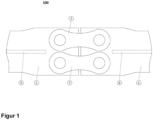
- Figure 1 shows the connection arrangement 100 according to the invention in a top view of the connection tabs 7, which are each part of a connection set and with which a first belt element 1 of a first spar element is to be connected to a second belt element 2 of a second spar element.
- the first belt element 1 of the first spar element is the root-side segment, while the second belt element 2 of the second spar element represents the tip-side segment.
- the connection arrangement 100 according to the invention therefore connects the spar elements of the segmented rotor blade.
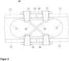
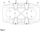
- Figure 2 and 3 show a side view of this connection arrangement 100 in detail.
- the entire spar of the rotor blade therefore has a first spar element with the two belt elements 1 and 3 and the web element 5 arranged between them and a second spar element with the two belt elements 2 and 4 and the web element 6 arranged between them.
- the belt elements 1, 2, 3, 4 can have a greater thickness or a greater width in the connection area than in the rest of the rotor blade in order to increase the load-bearing capacity of the connection.
- a significantly smaller or no increase in the cross-section of the belts is necessary, since the connection strength is extremely high.
- the belts are preferably reinforced with metal layers in the connection area, so that a fiber-metal laminate (FML) with high hole bearing strength is created.
- FML fiber-metal laminate
- the blade segments are connected to the cross bolts 9 with connecting plates 7 and 8.
- the connecting plates 7, 8 are preferably a metal, e.g. steel (e.g. 1.7225).
- Metallic connecting plates can be manufactured inexpensively from heavy plate (thickness preferably 10 to 100mm), for example by plasma cutting, water jet cutting, laser cutting, wire erosion or punching.
- the connecting plates can also be forged in variable, load-appropriate thicknesses.
- the connecting plates are made from an FML similar to the FML that is used in the connection area of the belts. This can reduce the weight of the connection technology.
- the connecting plates are made from a pure fiber-plastic composite to save further weight.
- the fibers can be optimally aligned in the direction of the load, particularly in the radial and tangential direction at the plate openings through which the cross bolts 9 are guided.
- the connecting plates 7 and 8 connect the two blade segments to the cross bolts 9 with maximum strength and minimum weight.
- the web elements 5, 6 of the blade segments are interrupted at the connection point to allow access to the connection technology, so that no thrust can be transmitted here.
- thrust connection elements 20 e.g. in the form of a push rod. These are connected to the cross bolts 9.
- the connection of the thrust connection elements 20 to the cross bolts 9 is particularly advantageous because these connection elements enable a high connection strength due to their solid construction, and thus no further connection points have to be formed on the blade segments. This allows mass and complexity to be reduced.
- the belt elements 1 and 2 as well as 3 and 4 are connected to the connecting plates 7 and 8 via the cross bolts 9.
- Two connecting sets are preferably used for each belt, each consisting of two cross bolts 9 and an outer connecting plate 7 and an inner connecting plate 8.
- the belt elements 1 and 2 are connected with two connecting sets, each connecting set having two connecting straps 7a and 8a in order to connect the belt elements 1 and 2 to one another by means of the cross bolts 9.
- the belt elements 1, 2, 3, 4 can differ in their width, thickness and the material used.
- different parameters can be selected in the root segment in particular than in the tip segment (e.g. a larger belt width or GRP instead of CFRP), but differences can also be implemented between the suction and pressure sides (e.g. a larger thickness on the suction side).
- the connecting tabs 7a and 8a on the suction side can also be designed differently in terms of width, thickness and material selection than the connecting tabs on the pressure side 7b and 8b in order to achieve a load-appropriate design with minimal weight.
- a cover 40 is required in the connection area, as shown in Figure 3 shown in order not to impair the aerodynamics of the rotor blades and to prevent the ingress of water.
- This cover 40 can consist of several segments in the profile circumferential direction.
- the cover is connected to the rotor blade on the suction and pressure side with connecting elements 43, 44, preferably screws.
- the front sides of the cross bolts 9 preferably serve as Screwing points.
- At the ends 41, 42 of the cover 40 this is connected to the blade in the most aerodynamically smooth way possible.
- An adhesive can be used for this, or the ends 41, 42 consist of a pre-tensioned rubber lip, which rests against the blade segments under pre-tension.
- the cover 40 increases the profile thickness locally in the connection area by approx. 100 mm (approx. 50 mm on the pressure and suction sides). Assuming a profile thickness of approx. 700 mm in the connection area, the aerodynamic losses due to the increase in profile thickness are minimal.
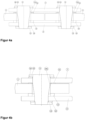
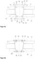
- the cross bolts 9 are preferably designed as radially and axially preloaded bolts (so-called RAX bolts) in combination with a radially and axially preloaded bushing 10a, 10b (so-called RAX bushing), as in the Figure 4a and in detail in Figure 4b is shown.
- Disc and securing elements 11, 12, 13, 14, 15, 16 can be provided.
- the connecting plates 7, 8 are clamped to the belt elements 1, 2 in the axial direction of the cross bolt 9. This creates the desired axial pre-tension in the RAX connection. On the other hand, this axial clamping also ensures that the connecting plates 7, 8 cannot twist under pressure load, since they are frictionally connected to the belt elements 1, 2.
- the push rods 20 can be connected directly to the cross bolts 9 without the washers 15 and 16. This reduces the number of individual parts and creates a positive connection of the push rods 20.
- the RAX socket 10b is designed without a flange, as in Figure 4b shown. This allows mass and costs to be saved.
- the height in the axial bolt direction is reduced and thus the bending load on the bolts.
- the projection beyond the aerodynamically optimal profile is reduced.
- the axial contact pressure on the belt elements 1, 2 is distributed more homogeneously over the surface of the disk 11 than when introduced via a flange.
- the cross bolt 9 is also conical at its ends.
- Conical expansion sleeves 30 and 31 are pressed with pressure covers 32, 33 and clamping screws 34 into the space between holes in the connecting plates 7, 8 and the conical bolt ends. With the help of the clamping screw 34, the pressure covers 32, 33 are connected to the cross bolt at opposite ends of the cross bolt 9.
- the expansion sleeves 30, 31 are made of a softer metal (e.g. softer steel or aluminum) and are axially slotted once or several times so that they can deform plastically and elastically during assembly. This achieves tolerance compensation between the holes in the connecting plates 7, 8 and the axis of the cross bolt 9 so that position deviations can be corrected.
- a softer metal e.g. softer steel or aluminum
- the connection between the cross bolt 9 and the connecting plates 7, 8 is free of play, which increases the fatigue strength of the connecting plates 7, 8.
- the axial space requirement on the inside can be reduced in this embodiment, because the cone, which is formed on the cross bolt 9 in the middle area to accommodate the bushing 10b, also serves as a cone for the expansion sleeve 30.
- the washer 11 in the form of a pressure piece can thus be made significantly flatter. Due to the compact design with minimal axial space requirement, this variant has the highest strength and the lowest weight.
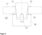
- the bushing 10b When installing the cross bolt 9, the bushing 10b must be fixed in the axial direction so that it is not pressed out of the hole in the belt.
- An assembly tool 50 with a suitable heel is suitable for this, as shown in Figure 6 which rests on both the washer 12 and the bushing 10b and adjusts their relative axial position.
- the assembly tool 50 can be, for example, a screw tensioning cylinder in combination with a tension bolt 51.
Landscapes
- Engineering & Computer Science (AREA)
- Life Sciences & Earth Sciences (AREA)
- Sustainable Development (AREA)
- Sustainable Energy (AREA)
- Chemical & Material Sciences (AREA)
- Combustion & Propulsion (AREA)
- Mechanical Engineering (AREA)
- General Engineering & Computer Science (AREA)
- Wind Motors (AREA)
Applications Claiming Priority (1)
| Application Number | Priority Date | Filing Date | Title |
|---|---|---|---|
| DE102023112869.8A DE102023112869B3 (de) | 2023-05-16 | 2023-05-16 | Segmentiertes Rotorblatt für Windkraftanlagen |
Publications (2)
| Publication Number | Publication Date |
|---|---|
| EP4464888A1 true EP4464888A1 (fr) | 2024-11-20 |
| EP4464888B1 EP4464888B1 (fr) | 2025-10-08 |
Family
ID=91128188
Family Applications (1)
| Application Number | Title | Priority Date | Filing Date |
|---|---|---|---|
| EP24176049.5A Active EP4464888B1 (fr) | 2023-05-16 | 2024-05-15 | Pale de rotor segmentée pour éoliennes |
Country Status (4)
| Country | Link |
|---|---|
| EP (1) | EP4464888B1 (fr) |
| DE (1) | DE102023112869B3 (fr) |
| DK (1) | DK4464888T3 (fr) |
| ES (1) | ES3058068T3 (fr) |
Cited By (1)
| Publication number | Priority date | Publication date | Assignee | Title |
|---|---|---|---|---|
| EP4667740A1 (fr) * | 2024-06-17 | 2025-12-24 | Deutsches Zentrum für Luft- und Raumfahrt e.V. | Pale de rotor segmentée pour éoliennes |
Families Citing this family (1)
| Publication number | Priority date | Publication date | Assignee | Title |
|---|---|---|---|---|
| DE102024116974A1 (de) * | 2024-06-17 | 2025-12-18 | Deutsches Zentrum für Luft- und Raumfahrt e.V. | Windkraftanlage |
Citations (10)
| Publication number | Priority date | Publication date | Assignee | Title |
|---|---|---|---|---|
| DE3109566C2 (de) | 1981-03-13 | 1983-04-07 | Messerschmitt-Bölkow-Blohm GmbH, 8000 München | Rotorblatt für Windenergiemaschinen und Spannvorrichtung zu seiner Montage |
| US20060083611A1 (en) * | 1999-12-24 | 2006-04-20 | Aloys Wobben | Butt connection for hollow profile members |
| US20080232966A1 (en) * | 2007-03-20 | 2008-09-25 | Wen-Chang Wang | Detachable blade assembly for horizontal-axis wind turbine |
| DE102008055513A1 (de) | 2007-12-13 | 2009-06-18 | General Electric Co. | Verbindungsstellenverklebungsrost für Windkraftanlagenrotorflügel |
| WO2009090537A2 (fr) | 2008-01-14 | 2009-07-23 | Clipper Windpower Technology, Inc. | Pale de rotor modulaire destinée à une turbine génératrice de courant et procédé d'assemblage d'une telle turbine au moyen de pales de rotor modulaires |
| WO2010023299A2 (fr) | 2008-08-31 | 2010-03-04 | Vestas Wind Systems A/S | Pale modulaire |
| WO2011067323A2 (fr) | 2009-12-02 | 2011-06-09 | Vestas Wind Systems A/S | Pale fractionnée pour éolienne |
| EP2288807B1 (fr) | 2008-05-07 | 2013-09-18 | Vestas Wind Systems A/S | Aube sectionnelle |
| CN203670111U (zh) * | 2013-12-06 | 2014-06-25 | 北京金风科创风电设备有限公司 | 分段式风机叶片 |
| WO2016087594A1 (fr) | 2014-12-05 | 2016-06-09 | Deutsches Zentrum für Luft- und Raumfahrt e.V. | Pale de rotor pour éoliennes |
-
2023
- 2023-05-16 DE DE102023112869.8A patent/DE102023112869B3/de active Active
-
2024
- 2024-05-15 DK DK24176049.5T patent/DK4464888T3/da active
- 2024-05-15 ES ES24176049T patent/ES3058068T3/es active Active
- 2024-05-15 EP EP24176049.5A patent/EP4464888B1/fr active Active
Patent Citations (10)
| Publication number | Priority date | Publication date | Assignee | Title |
|---|---|---|---|---|
| DE3109566C2 (de) | 1981-03-13 | 1983-04-07 | Messerschmitt-Bölkow-Blohm GmbH, 8000 München | Rotorblatt für Windenergiemaschinen und Spannvorrichtung zu seiner Montage |
| US20060083611A1 (en) * | 1999-12-24 | 2006-04-20 | Aloys Wobben | Butt connection for hollow profile members |
| US20080232966A1 (en) * | 2007-03-20 | 2008-09-25 | Wen-Chang Wang | Detachable blade assembly for horizontal-axis wind turbine |
| DE102008055513A1 (de) | 2007-12-13 | 2009-06-18 | General Electric Co. | Verbindungsstellenverklebungsrost für Windkraftanlagenrotorflügel |
| WO2009090537A2 (fr) | 2008-01-14 | 2009-07-23 | Clipper Windpower Technology, Inc. | Pale de rotor modulaire destinée à une turbine génératrice de courant et procédé d'assemblage d'une telle turbine au moyen de pales de rotor modulaires |
| EP2288807B1 (fr) | 2008-05-07 | 2013-09-18 | Vestas Wind Systems A/S | Aube sectionnelle |
| WO2010023299A2 (fr) | 2008-08-31 | 2010-03-04 | Vestas Wind Systems A/S | Pale modulaire |
| WO2011067323A2 (fr) | 2009-12-02 | 2011-06-09 | Vestas Wind Systems A/S | Pale fractionnée pour éolienne |
| CN203670111U (zh) * | 2013-12-06 | 2014-06-25 | 北京金风科创风电设备有限公司 | 分段式风机叶片 |
| WO2016087594A1 (fr) | 2014-12-05 | 2016-06-09 | Deutsches Zentrum für Luft- und Raumfahrt e.V. | Pale de rotor pour éoliennes |
Cited By (1)
| Publication number | Priority date | Publication date | Assignee | Title |
|---|---|---|---|---|
| EP4667740A1 (fr) * | 2024-06-17 | 2025-12-24 | Deutsches Zentrum für Luft- und Raumfahrt e.V. | Pale de rotor segmentée pour éoliennes |
Also Published As
| Publication number | Publication date |
|---|---|
| EP4464888B1 (fr) | 2025-10-08 |
| DE102023112869B3 (de) | 2024-08-22 |
| ES3058068T3 (en) | 2026-03-06 |
| DK4464888T3 (da) | 2026-01-12 |
Similar Documents
| Publication | Publication Date | Title |
|---|---|---|
| DE102014118004B3 (de) | Rotorblatt für Windkraftanlagen | |
| EP4464888B1 (fr) | Pale de rotor segmentée pour éoliennes | |
| DE102006022279B4 (de) | Rotorblatt für eine Windenergieanlage | |
| EP4038271B1 (fr) | Pale de rotor d'éolienne et procédé de liaison de deux segments de pale de rotor | |
| EP2910773B1 (fr) | Connexion pour pale de rotor | |
| EP1398499B1 (fr) | Fixation des aubes sur le moyeu d'éolienne | |
| EP3469212B1 (fr) | Rotor pour éolienne, pale de rotor pour éolienne, manchon et procédé de montage d'un rotor | |
| EP4155530B1 (fr) | Pale de rotor pour éolienne | |
| DE102017106875B4 (de) | Windkraftanlage und Verfahren zu dessen Montage | |
| DE102016123346B3 (de) | Faserverbundbauteil, Faserverbundstruktur und Herstellung derselben | |
| EP3376024A1 (fr) | Pale de rotor d'éolienne divisible comprenant une liaison par boulonnage | |
| EP3425195A1 (fr) | Pale de rotor d'éolienne divisible comprenant un module de douilles | |
| EP3775532B1 (fr) | Pale de rotor d'éolienne et éolienne | |
| EP4400712A1 (fr) | Insert pour une pale de rotor d'éolienne et pale de rotor d'éolienne | |
| EP4667740A1 (fr) | Pale de rotor segmentée pour éoliennes | |
| EP3974602B1 (fr) | Dispositif d'accouplement permettant d'accoupler des segments d'une tour d'une éolienne et procédé de montage pour cela | |
| EP3781808A1 (fr) | Pale de rotor d'éolienne et éolienne | |
| EP4667739A1 (fr) | Installation eolienne | |
| EP4400713A1 (fr) | Pale de rotor d'éolienne divisée et procédé de liaison de deux segments de pale de rotor d'une pale de rotor d'éolienne | |
| WO2023247714A1 (fr) | Procédé de production d'un élément composite à base de fibres et élément creux composite à base de fibres, et éolienne associée | |
| EP3159536A1 (fr) | Ensemble rotor pour une turbine |
Legal Events
| Date | Code | Title | Description |
|---|---|---|---|
| PUAI | Public reference made under article 153(3) epc to a published international application that has entered the european phase |
Free format text: ORIGINAL CODE: 0009012 |
|
| STAA | Information on the status of an ep patent application or granted ep patent |
Free format text: STATUS: THE APPLICATION HAS BEEN PUBLISHED |
|
| AK | Designated contracting states |
Kind code of ref document: A1 Designated state(s): AL AT BE BG CH CY CZ DE DK EE ES FI FR GB GR HR HU IE IS IT LI LT LU LV MC ME MK MT NL NO PL PT RO RS SE SI SK SM TR |
|
| STAA | Information on the status of an ep patent application or granted ep patent |
Free format text: STATUS: REQUEST FOR EXAMINATION WAS MADE |
|
| 17P | Request for examination filed |
Effective date: 20241129 |
|
| RBV | Designated contracting states (corrected) |
Designated state(s): AL AT BE BG CH CY CZ DE DK EE ES FI FR GB GR HR HU IE IS IT LI LT LU LV MC ME MK MT NL NO PL PT RO RS SE SI SK SM TR |
|
| GRAP | Despatch of communication of intention to grant a patent |
Free format text: ORIGINAL CODE: EPIDOSNIGR1 |
|
| STAA | Information on the status of an ep patent application or granted ep patent |
Free format text: STATUS: GRANT OF PATENT IS INTENDED |
|
| INTG | Intention to grant announced |
Effective date: 20250429 |
|
| GRAS | Grant fee paid |
Free format text: ORIGINAL CODE: EPIDOSNIGR3 |
|
| GRAA | (expected) grant |
Free format text: ORIGINAL CODE: 0009210 |
|
| STAA | Information on the status of an ep patent application or granted ep patent |
Free format text: STATUS: THE PATENT HAS BEEN GRANTED |
|
| AK | Designated contracting states |
Kind code of ref document: B1 Designated state(s): AL AT BE BG CH CY CZ DE DK EE ES FI FR GB GR HR HU IE IS IT LI LT LU LV MC ME MK MT NL NO PL PT RO RS SE SI SK SM TR |
|
| REG | Reference to a national code |
Ref country code: GB Ref legal event code: FG4D Free format text: NOT ENGLISH Ref country code: CH Ref legal event code: F10 Free format text: ST27 STATUS EVENT CODE: U-0-0-F10-F00 (AS PROVIDED BY THE NATIONAL OFFICE) Effective date: 20251008 |
|
| REG | Reference to a national code |
Ref country code: DE Ref legal event code: R096 Ref document number: 502024000280 Country of ref document: DE |
|
| REG | Reference to a national code |
Ref country code: IE Ref legal event code: FG4D Free format text: LANGUAGE OF EP DOCUMENT: GERMAN |
|
| REG | Reference to a national code |
Ref country code: DK Ref legal event code: T3 Effective date: 20260105 |
|
| REG | Reference to a national code |
Ref country code: NL Ref legal event code: MP Effective date: 20251008 |
|
| REG | Reference to a national code |
Ref country code: ES Ref legal event code: FG2A Ref document number: 3058068 Country of ref document: ES Kind code of ref document: T3 Effective date: 20260306 |
|
| PG25 | Lapsed in a contracting state [announced via postgrant information from national office to epo] |
Ref country code: NL Free format text: LAPSE BECAUSE OF FAILURE TO SUBMIT A TRANSLATION OF THE DESCRIPTION OR TO PAY THE FEE WITHIN THE PRESCRIBED TIME-LIMIT Effective date: 20251008 |
|
| REG | Reference to a national code |
Ref country code: LT Ref legal event code: MG9D |
|
| PG25 | Lapsed in a contracting state [announced via postgrant information from national office to epo] |
Ref country code: NO Free format text: LAPSE BECAUSE OF FAILURE TO SUBMIT A TRANSLATION OF THE DESCRIPTION OR TO PAY THE FEE WITHIN THE PRESCRIBED TIME-LIMIT Effective date: 20260108 |
|
| PG25 | Lapsed in a contracting state [announced via postgrant information from national office to epo] |
Ref country code: HR Free format text: LAPSE BECAUSE OF FAILURE TO SUBMIT A TRANSLATION OF THE DESCRIPTION OR TO PAY THE FEE WITHIN THE PRESCRIBED TIME-LIMIT Effective date: 20251008 Ref country code: FI Free format text: LAPSE BECAUSE OF FAILURE TO SUBMIT A TRANSLATION OF THE DESCRIPTION OR TO PAY THE FEE WITHIN THE PRESCRIBED TIME-LIMIT Effective date: 20251008 |
|
| PG25 | Lapsed in a contracting state [announced via postgrant information from national office to epo] |
Ref country code: RS Free format text: LAPSE BECAUSE OF FAILURE TO SUBMIT A TRANSLATION OF THE DESCRIPTION OR TO PAY THE FEE WITHIN THE PRESCRIBED TIME-LIMIT Effective date: 20260108 |
|
| PG25 | Lapsed in a contracting state [announced via postgrant information from national office to epo] |
Ref country code: IS Free format text: LAPSE BECAUSE OF FAILURE TO SUBMIT A TRANSLATION OF THE DESCRIPTION OR TO PAY THE FEE WITHIN THE PRESCRIBED TIME-LIMIT Effective date: 20260208 |
|
| PG25 | Lapsed in a contracting state [announced via postgrant information from national office to epo] |
Ref country code: PT Free format text: LAPSE BECAUSE OF FAILURE TO SUBMIT A TRANSLATION OF THE DESCRIPTION OR TO PAY THE FEE WITHIN THE PRESCRIBED TIME-LIMIT Effective date: 20260209 |
|
| PG25 | Lapsed in a contracting state [announced via postgrant information from national office to epo] |
Ref country code: PL Free format text: LAPSE BECAUSE OF FAILURE TO SUBMIT A TRANSLATION OF THE DESCRIPTION OR TO PAY THE FEE WITHIN THE PRESCRIBED TIME-LIMIT Effective date: 20251008 |
|
| PG25 | Lapsed in a contracting state [announced via postgrant information from national office to epo] |
Ref country code: LV Free format text: LAPSE BECAUSE OF FAILURE TO SUBMIT A TRANSLATION OF THE DESCRIPTION OR TO PAY THE FEE WITHIN THE PRESCRIBED TIME-LIMIT Effective date: 20251008 |