EP4465096A1 - Rideau de lumière - Google Patents
Rideau de lumière Download PDFInfo
- Publication number
- EP4465096A1 EP4465096A1 EP23173804.8A EP23173804A EP4465096A1 EP 4465096 A1 EP4465096 A1 EP 4465096A1 EP 23173804 A EP23173804 A EP 23173804A EP 4465096 A1 EP4465096 A1 EP 4465096A1
- Authority
- EP
- European Patent Office
- Prior art keywords
- light
- receiving
- grid
- deflection element
- light grid
- Prior art date
- Legal status (The legal status is an assumption and is not a legal conclusion. Google has not performed a legal analysis and makes no representation as to the accuracy of the status listed.)
- Granted
Links
Images



Classifications
-
- G—PHYSICS
- G01—MEASURING; TESTING
- G01V—GEOPHYSICS; GRAVITATIONAL MEASUREMENTS; DETECTING MASSES OR OBJECTS; TAGS
- G01V8/00—Prospecting or detecting by optical means
- G01V8/10—Detecting, e.g. by using light barriers
- G01V8/20—Detecting, e.g. by using light barriers using multiple transmitters or receivers
Definitions
- the present invention relates to a light grid for detecting objects present in a surveillance area.
- a light grid is a combination of several light barriers and is alternatively also called a light curtain, although there are several designs of light barriers.
- a light receiver and a light transmitter are arranged on opposite sides of a monitoring area.
- the monitoring area is clear, the light emitted by the light transmitter hits the light receiver and is converted into electrical signals that are transmitted to an evaluation unit. If an object is in the monitoring area, the light path between the light receiver and the light transmitter, which runs along a reception axis, is interrupted, which means that a drop in signal is detected and a corresponding monitoring signal can be output.
- the light receiver and the light transmitter are arranged on the same side of the monitoring area.
- the emitted light is reflected back in the direction of the light receiver by a reflector arranged on the opposite side of the monitoring area.
- reflection light sensor Another type of light barrier is the reflection light sensor. As with the reflection light barrier, the light receiver and the light transmitter are located on the same side of the monitoring area. In contrast to a reflection light barrier Object detection does not occur by interrupting the light path, but by reflection of the transmitted light by an object present in the monitoring area in the direction of the light receiver.
- a light grid is provided with several light receivers and several light transmitters, whereby several spaced-apart reception axes are defined, which usually run parallel to one another in a plane, although other geometric configurations with regard to the arrangement of the reception axes are also possible, for example a non-parallel course of the reception axes.
- the light receivers are usually combined in a receiver unit and the light transmitters in a transmitter unit. All of the light barrier designs explained above can also be implemented as light grids or light curtains.
- a light grid can be used to monitor a larger monitoring area. Due to the multiple reception axes of a light grid, the size and/or lateral position of a detected object can also be determined within the resolution specified by the distance between the reception axes.
- the reception axes of a light grid define respective reception channels or viewing areas in conjunction with an evaluation unit and, if necessary, a control unit for controlling the light transmitters.
- a sequential activation of the reception channels can be provided so that, for example, only one reception channel or at least only a subset of all reception channels is active at a certain point in time. All other reception channels, ie the associated light receivers or light transmitters, are deactivated.
- each receiving channel is generally assigned its own light receiver, so that light grids with a large number of receiving channels incur correspondingly high production costs due to the number of light receivers required.
- a marking is illuminated using the light transmitter and projected onto a spatially resolving light receiver.
- the object is detected by comparing a current image with a stored image of the marking taken when the protective field was free of objects.
- a light grid according to the invention for detecting objects present in a surveillance area comprises at least one receiving module, wherein the at least one receiving module comprises a spatially resolving light receiver with a light-sensitive receiving surface and at least one deflection element and has at least two receiving channels, wherein each receiving channel has a respective light entry aperture and a receiving axis, wherein the receiving surface is divided into at least two non-overlapping partial surfaces, wherein each receiving channel is assigned a respective partial surface, and wherein at least a part of the receiving axes runs through the at least one deflection element.
- the at least one receiving module comprises a spatially resolving light receiver with a light-sensitive receiving surface and at least one deflection element and has at least two receiving channels, wherein each receiving channel has a respective light entry aperture and a receiving axis, wherein the receiving surface is divided into at least two non-overlapping partial surfaces, wherein each receiving channel is assigned a respective partial surface, and wherein at least a part of the receiving axes runs through the at least
- the light entry aperture defines a field of view of the assigned reception channel, i.e. a spatial area or solid angle range from which received light signals are recorded and forwarded in the direction of the light receiver.
- the term "reception channel” mainly refers to the optical or optoelectronic components that are assigned to a respective field of view or a respective reception axis. In a figurative sense, the term “reception channel” can also extend to a corresponding logical channel, which can be defined in terms of circuitry in an evaluation unit assigned to the light grid.
- non-overlapping partial areas does not necessarily refer to a physical division of the reception area, but also a logical division, which can be carried out, for example, within an evaluation unit connected to the light receiver.
- an image sensor with light-sensitive reception elements (pixels) arranged in rows and columns can be used, the image area of which is divided into so-called non-overlapping ROIs (Region of Interest).
- the light receiver can also be formed by a two-channel PSD receiver (Position Sensitive Device).
- a respective receiving light spot can be generated from the received light signals, which hits the partial area of the light receiver assigned to this receiving channel.
- the at least one deflection element serves in particular to adapt a desired distance between the light entry apertures of a receiving module to the distance between the partial surfaces of the receiving surface specified by the geometry of the light receiver.
- the deflection element can deflect light signals that propagate along the associated receiving axis and pass through the light entry aperture once or several times.
- a receiving module can be designed in such a way that all receiving axes or all receiving channels run through the deflection element.
- two channels run through a common deflection element or through two separate deflection elements and in a third receiving channel the light signals reach the assigned partial area of the light receiver directly, i.e. without deflection.
- the deflection element(s) of a respective receiving module can be designed as separate, channel-separated components or as an integrated component for several receiving channels.
- a light grid according to the invention it is possible for a light grid according to the invention to have only one receiving module.
- the light grid advantageously comprises several, preferably identical, receiving modules so that a correspondingly large monitoring area can be monitored.
- one advantage is that the number of light receivers required is smaller than the number of existing receiving channels. This enables a space-saving arrangement of the Light receivers in a common receiver unit are possible. At the same time, the material and manufacturing costs are reduced due to the comparatively smaller number of light receivers, which brings with it a significant cost advantage.
- a further advantage is that, regardless of the desired grid size for the arrangement of the light entry apertures or the receiving optics, a universal circuit board can be used on which one or preferably several light receivers, i.e. the light receivers of a plurality of receiving modules, can be arranged. The adaptation to a desired grid size is then carried out by appropriate dimensioning of the deflection elements.
- the light grid according to the invention can be implemented as a one-way light grid, a reflection light grid or a scanning light grid in accordance with the designs of light barriers explained above.
- the light entry apertures of two adjacent receiving channels have a respective base distance which is greater than the distance between the partial areas assigned to these receiving channels.
- distance and base distance are understood to mean in particular the respective center distances of the respective receiving channels.
- a respective deflection element can initially deflect the receiving axis by 90° and then again by 90° in the opposite direction after a certain distance, so that the receiving axis experiences a certain lateral offset. In this way, the distance between the receiving channels within the assigned receiving module can be reduced to such an extent that the receiving channels of a respective receiving module are directed to the common light receiver.
- the deflection element is designed as a mirror arrangement, as a prism element or as an optical waveguide. If the deflection element is designed as a prism element or optical waveguide, the deflection takes place through internal reflection on the walls of the prism element or the optical waveguide.
- the deflection element can be made, for example, from a transparent solid material such as glass or plastic or as a hollow element.
- the outer walls can be coated with a reflective material to improve the reflection properties, for example with a metal vapor deposition.
- the deflection element is preferably designed in such a way that total reflection occurs on its walls, so that an additional coating that causes costs can be dispensed with.
- the deflection element can also be designed as a mirror arrangement with one or more mirror surfaces.
- the light grid comprises a transmission arrangement for transmitting light signals into the monitoring area, wherein the light grid is set up to determine the distance to an object present in the monitoring area on the basis of the light transit time of the light signals transmitted by the transmission arrangement, remitted by an object and detected by the light receiver.
- This embodiment can also be referred to as a so-called scanning TOF light grid (from English "Time Of Flight").
- the transmission arrangement and the light receivers can be connected to a control unit or a combined evaluation and control unit, which can control the transmission arrangement to transmit the light signals, for example in the form of one or more light pulses, and can evaluate the electrical reception signals generated by the light receiver on the basis of the detected light signals, in order to determine the light transit time between the time of transmission of a light signal and its reception and from this to determine the distance to the object.
- a control unit or a combined evaluation and control unit which can control the transmission arrangement to transmit the light signals, for example in the form of one or more light pulses, and can evaluate the electrical reception signals generated by the light receiver on the basis of the detected light signals, in order to determine the light transit time between the time of transmission of a light signal and its reception and from this to determine the distance to the object.
- the light receiver advantageously comprises a SPAD array.
- a SPAD array is an array or a two-dimensional matrix of single-photon avalanche diodes, where SPAD is the abbreviation for the English term "Single Photon Avalanche Diode".
- SPAD arrays are particularly suitable for distance measurement based on the time of flight of light.
- individual ROIs can usually be defined, whereby only those pixels or diode elements of the SPAD array that are actually illuminated by a respective receiving light spot are used for the evaluation.
- the signal-to-noise ratio can be reduced.
- This option for defining ROIs can also be used to divide the reception area into the aforementioned sub-areas.
- the light entry aperture of a respective receiving channel is defined by at least one diaphragm, which is provided between a receiving optics arranged upstream of the deflection element and a light entry surface of the deflection element and/or between a light exit surface of the deflection element and the light receiver.
- the diaphragm at least predominantly determines the field of view of a respective receiving channel for respective beams of the received light signals and is preferably selected such that crosstalk of received light signals in adjacent receiving channels is avoided at least for objects whose distance from the light grid lies within the limits of a defined detection range of the light grid, in order to achieve a desired lateral resolution of the light grid.
- the aforementioned Upstream receiving optics are provided in front of the deflection element, viewed in the direction of propagation of the received light signals.
- Each receiving channel can have one or more associated receiving optics.
- the receiving optics of different receiving channels can preferably be designed as a lens array in which several lenses are formed in a common integrated or monolithic component.
- a temperature-related change in length occurs to the same extent, so that, for example, the distance between the receiving optics of a receiving module and the offset of the receiving axes generated by the at least one deflection element change to the same extent, so that the viewing areas of the individual receiving channels remain the same even when the temperature changes and, in particular, a parallel alignment of the receiving channels is maintained even when the temperature changes.
- the aperture is advantageously arranged in the image plane of the receiving optics.
- an aperture can be arranged on a light entry surface or a light exit surface of the deflection element.
- the aperture can, for example, be applied or produced directly on the light entry surface or the light exit surface of the deflection element.
- a separate aperture carrier can also be provided.
- the aperture can be produced on the deflection element or on a separate aperture carrier, for example, by applying a corresponding coating using masks or in the form of a so-called laser-generated aperture, whereby the aperture is produced by introducing high-energy laser radiation into the optical system in the (partially) assembled state at the intended location by releasing energy. This method is known, for example, in DE 10 2018 128 669 A1 described.
- the light entry surface, light exit surface and/or at least one reflection surface of a respective deflection element are designed with an optically effective geometry.
- a respective optically effective geometry gives the deflection element additional beam-forming or imaging properties, for example through a convex or concave curvature of one or more of the aforementioned surfaces. This reduces the number of optical elements to be mounted and adjusted, which can reduce the manufacturing effort and also potential sources of adjustment errors.
- a respective deflection element is designed and arranged in such a way that an aperture of the associated receiving optics is imaged onto the receiving surface by means of the optically effective geometry of the deflection element.
- the size of the receiving light spot on the light receiver therefore depends mainly on the size of the receiving optics and the geometry of the beam path downstream of the receiving optics.
- the light grid has at least one circuit board, which has a side facing away from the monitoring area and a side facing the monitoring area, with a light receiver assigned to the conductor being arranged on the side facing away from the monitoring area.
- the light-sensitive receiving surface thus faces away from the monitoring area.
- the deflection element is designed such that a respective receiving axis is deflected by an order of magnitude of 180°.
- the circuit board mentioned can, for example, be a common circuit board for several light receivers or receiving modules. In principle, however, a separate circuit board can also be provided for each receiving module or for each light receiver.
- a common circuit board can be provided for several light receivers or receiving modules.
- a transmitting unit (not shown) can be arranged, which Transmitted light is emitted into the monitoring area, which is detected by the receiving module 12.
- the two receiving optics 26.1, 26.2 are arranged laterally spaced from each other with a base distance B and are formed in an integrated component, which can also be referred to as an optical module or lens array.
- the received light spreads out along two receiving axes 24.1, 24.2, which each run through the lens centers of the two receiving optics 26.1, 26.2.
- the received light bundled by the receiving optics 26.1, 26.2 then enters a respective deflection element 30.1 or 30.2, which is designed as an optical waveguide or prism element.
- a first deflection takes place at a first reflection surface 32, the deflection angle being slightly more than 90°.
- a second deflection then takes place at a second reflection surface 34, the reflection angle here being approximately 90°.
- Both deflections are directed in opposite directions to one another, so that the exit direction from the deflection elements 30.1, 30.2, relative to the reception axes 24.1 and 24.2, is approximately the same as the entry direction of the received light into the deflection elements 30.1, 30.2.
- the respective first and second reflection surfaces 32, 34 are concavely curved and thus have additional beam-forming properties.
- the two deflection elements 30.1, 30.2 are mirror-symmetrical to one another and arranged in such a way that the original distance between the reception axes 24.1, 24.2 is reduced to such an extent that both reception light beams can be detected by the single light receiver 14.
- the distance between the reception axes 24.1, 24.2 is in principle reduced to the center distance A of the partial surfaces 18.1, 18.2.
- the spatially resolving light receiver 14 shown in plan view has a receiving surface 16 which has a plurality of light-sensitive receiving elements 17 (eg SPAD elements) arranged in rows and columns, which are schematically represented by small squares.
- the receiving surface 16 is divided into two partial surfaces 18.1, 18.2, with a dashed line marking the boundary between the two partial surfaces 18.1, 18.2.
- the transmitted light beams propagating along the receiving axes 24.1, 24.2 are bundled in the plane of the receiving surface 16 to form a respective received light spot 20.1, 20.2.
- the received light propagating along the receiving axis 24.1 is focused into the received light spot 20.1, while the transmitted light beam propagating along the receiving axis 24.2 is focused into the received light spot 20.2.
- the receiving module 12 is configured and adjusted in such a way that the received light spot 20.1 completely impinges on the partial surface 18.1 and the received light spot 20.2 completely impinges on the partial surface 18.2.
- the distance between the received light spots 20.1, 20.2 essentially corresponds to the center distance A of the partial surfaces 18.1, 18.2.
- the two receiving axes 24.1, 24.2 together with the partial surfaces 18.1, 18.2 form a respective receiving channel, whereby the receiving optics 26.1, 26.2 and the deflection elements 30.1, 30.2 are arranged as shown in Fig. 1 assigned to one of these reception channels.
- the fields of view or "angles of view" of the respective received light beams are limited by means of diaphragms 36.1, 36.2.
- the size of the Received light spots 20.1, 20.2 are limited in such a way that a certain safety distance remains between the two received light spots 20.1, 20.2 or at least no overlap occurs.
- each partial area 18.1, 18.2 only detects light from the respective assigned receive channel.
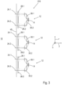
- Fig. 3 shows a light grid 210 according to a second embodiment.
- the light grid 210 comprises three similar receiving modules 12, which in their design are similar to the receiving module 12 of Fig. 1 and are arranged along an axis running in the y-direction. For reasons of clarity, only the reception axes 24.1, 24.2 are shown instead of the transmitted light beams.
- the distances between the individual reception modules 12 in the y-direction are selected such that all reception channels or reception axes 24.1, 24.2 run at the same distance from one another within the plane of the drawing.
- the front pane 40 is designed as a continuous front pane 40 which extends over all six reception channels.
- all six receiving lenses 26.1, 26.2 can be integrated in a common lens array or optical module (not shown).
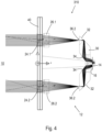
- Fig. 4 3 shows a light grid 310 according to a third embodiment.
- the structure of the light grid 310 corresponds in essential aspects to the structure of the light grid 110 of Fig. 1 , so that only the essential differences are described below.
- an optical module with the two receiving optics 26.1, 26.2 these are designed as individual elements.
- an integrated deflection element 30 is provided, which, however, functionally corresponds to the adjacent arrangement of two separate deflection elements 30.1, 30.2.
- Another difference is that the panels 36.1, 36.2 are not designed as separate components (as in Fig.
- the deflection element 30 is, for example in the form of a coating or vapor deposition deposited thereon. Furthermore, the reflection surfaces 32, 34 of the deflection element 30 have a somewhat larger radius of curvature.
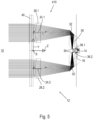
- Fig. 5 shows a light grid 410 according to a fourth embodiment, which essentially corresponds to the light grid 310 of Fig. 4
- the apertures 36.1, 36.2 are not applied to the light entry side of the deflection element 30, but rather to its light exit side.
- the apertures 36.1, 36.2 can be produced here, for example, with the aid of a processing laser directly on the light exit side by focusing the processing laser in such a way that its focal point is in the plane of the light exit side of the deflection element 30.
- the reflection surfaces 32, 34 of the deflection element 30 of the light grid 410 are not curved but flat and thus do not have an optically effective geometry.
- a light grid 510 according to a fifth embodiment is shown.
- the receiving surface 16 of the light receiver 14 is located on a side facing away from the monitoring area 10.
- the light receiver 14 is arranged on a circuit board 42, which has passage openings 44.1, 44.2 for the received light.
- the deflection element 30 has a slightly different geometry compared to the deflection elements 30, 30.1, 30.2 of the light grids 110 to 410. Only the second reflection surfaces 34 are optically effective due to their concave curvature.
- the first reflection surfaces 32 are flat and therefore not optically effective.
- Fig. 7 shows a light grid 610 according to a sixth embodiment, which is similar to the light grid 310 ( Fig. 4 ).
- the receiving module 12 of the light grid 610 additionally has a third receiving channel, which is arranged centrally between the first and the second receiving channel.
- the light receiver 14 has a total of three partial surfaces arranged in series.
- the receiving axis 24.3 of the third receiving channel is not deflected, since there are no corresponding surfaces of the deflection element 30 in the receiving light path of the third receiving channel, but only a plane-parallel section or an opening.
- a further receiving optics 26.4 is provided, which is located between the receiving optics 26.3 and the deflection element 30.
- the light grids 310 to 610 ( Fig. 4 to 7 ) several receiving modules 12 can be provided, which can be arranged in series or in another configuration.
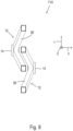
- FIG. 8 A further light grid 710 according to a seventh embodiment is described.
- Fig. 8 a top view of the light grid 710.
- the receiving modules 12 are arranged in such a way that the respective light entry surfaces of the deflection elements 30 (represented by square surfaces) are distributed along an axis running in the y-direction, with one arm of one deflection element 30 extending between the two arms of the other deflection element.
- the deflection elements 30 are also slightly tilted relative to one another, so that the light receivers 14 not only have an offset in the y-direction, but also an offset in the x-direction.
- All exemplary light grids 110 to 710 can basically be designed as one-way light grids, reflection grids or as scanning light grids.
- the light grids 110 to 710 can comprise transmission arrangements that have at least one light transmitter.
- the light grids 110 to 710 can be designed as distance-measuring scanning light grids.
- a SPAD array can be used as the light receiver 14, for example.
- Each receiving channel can be assigned a respective light transmitter (not shown), with the light transmitters and the light receiver 14 being connected to a common evaluation and control unit.
- the arrangement of the light transmitters and the receiving module(s) 12 is such that a light pulse emitted by a respective light transmitter is reflected by an object that may be present in the monitoring area in the direction of the assigned receiving module 12.
- the evaluation and control unit is set up to measure the light propagation time between the emission of the light pulse and the detection by the light receiver 14 and to use this to determine the distance of the detected object to the light grid.
- a common light transmitter can also be provided for several reception channels, preferably for all reception channels of a respective reception module 12. This allows a distance determination to be carried out simultaneously for the several receiving channels.
- individual receiving elements 17 can be deactivated so that only those receiving elements 17 that are actually illuminated by a receiving light spot 20.1, 20.2 contribute to a detection signal.
- the interference sensitivity of the light receiver 14 can be significantly reduced, which is particularly advantageous for a light receiver designed as a SPAD light receiver.
- SPAD light receivers 14 in particular, in conjunction with the evaluation and control unit, enable a circuit-technical definition of the partial areas 18.1, 18.2 within the entire receiving area 16 of the light receiver 14.
Landscapes
- Physics & Mathematics (AREA)
- Life Sciences & Earth Sciences (AREA)
- General Life Sciences & Earth Sciences (AREA)
- General Physics & Mathematics (AREA)
- Geophysics (AREA)
- Geophysics And Detection Of Objects (AREA)
Priority Applications (1)
| Application Number | Priority Date | Filing Date | Title |
|---|---|---|---|
| EP23173804.8A EP4465096B1 (fr) | 2023-05-17 | 2023-05-17 | Rideau de lumière |
Applications Claiming Priority (1)
| Application Number | Priority Date | Filing Date | Title |
|---|---|---|---|
| EP23173804.8A EP4465096B1 (fr) | 2023-05-17 | 2023-05-17 | Rideau de lumière |
Publications (2)
| Publication Number | Publication Date |
|---|---|
| EP4465096A1 true EP4465096A1 (fr) | 2024-11-20 |
| EP4465096B1 EP4465096B1 (fr) | 2026-01-21 |
Family
ID=86387100
Family Applications (1)
| Application Number | Title | Priority Date | Filing Date |
|---|---|---|---|
| EP23173804.8A Active EP4465096B1 (fr) | 2023-05-17 | 2023-05-17 | Rideau de lumière |
Country Status (1)
| Country | Link |
|---|---|
| EP (1) | EP4465096B1 (fr) |
Citations (7)
| Publication number | Priority date | Publication date | Assignee | Title |
|---|---|---|---|---|
| DE102004038940A1 (de) * | 2004-08-11 | 2006-02-23 | Leuze Electronic Gmbh & Co Kg | Optischer Sensor |
| EP1811427A1 (fr) | 2006-01-24 | 2007-07-25 | Sick Ag | Procédé et dispositif pour la surveillance d'un domaine |
| EP1892495A2 (fr) * | 2006-03-09 | 2008-02-27 | Knestel Elektronik GmbH | Dispositif et procédé destinés à l'évaluation des impacts du tir |
| EP1950584A1 (fr) * | 2007-01-26 | 2008-07-30 | Sick Ag | Capteur optoélectronique et procédé de réception doté d'un correcteur de lumière parasite |
| US20090185164A1 (en) * | 2008-01-18 | 2009-07-23 | Sumitomo Electric Industries, Ltd. | Method of inspecting food and inspection apparatus implementing the same |
| JP2014055804A (ja) * | 2012-09-11 | 2014-03-27 | Nec Computertechno Ltd | 物体検知装置、メカトロニクス装置および物体検知方法 |
| DE102018128669A1 (de) | 2018-11-15 | 2020-05-20 | Sick Ag | Verfahren zum Herstellen eines optischen Systems |
-
2023
- 2023-05-17 EP EP23173804.8A patent/EP4465096B1/fr active Active
Patent Citations (7)
| Publication number | Priority date | Publication date | Assignee | Title |
|---|---|---|---|---|
| DE102004038940A1 (de) * | 2004-08-11 | 2006-02-23 | Leuze Electronic Gmbh & Co Kg | Optischer Sensor |
| EP1811427A1 (fr) | 2006-01-24 | 2007-07-25 | Sick Ag | Procédé et dispositif pour la surveillance d'un domaine |
| EP1892495A2 (fr) * | 2006-03-09 | 2008-02-27 | Knestel Elektronik GmbH | Dispositif et procédé destinés à l'évaluation des impacts du tir |
| EP1950584A1 (fr) * | 2007-01-26 | 2008-07-30 | Sick Ag | Capteur optoélectronique et procédé de réception doté d'un correcteur de lumière parasite |
| US20090185164A1 (en) * | 2008-01-18 | 2009-07-23 | Sumitomo Electric Industries, Ltd. | Method of inspecting food and inspection apparatus implementing the same |
| JP2014055804A (ja) * | 2012-09-11 | 2014-03-27 | Nec Computertechno Ltd | 物体検知装置、メカトロニクス装置および物体検知方法 |
| DE102018128669A1 (de) | 2018-11-15 | 2020-05-20 | Sick Ag | Verfahren zum Herstellen eines optischen Systems |
Also Published As
| Publication number | Publication date |
|---|---|
| EP4465096B1 (fr) | 2026-01-21 |
Similar Documents
| Publication | Publication Date | Title |
|---|---|---|
| DE102017214574B4 (de) | Lichtsensor | |
| EP3673290A1 (fr) | Dispositif d'émission pour un scanner lidar présentant un miroir de balayage recouvert par un élément de recouvrement | |
| EP2629050B1 (fr) | Capteur de triangulation | |
| DE10146639A1 (de) | Lichtgitter mit Strahlteiler | |
| DE102020102247A1 (de) | Optoelektronischer Sensor und Verfahren zur Erfassung von Objekten | |
| EP3379294A1 (fr) | Optique d'émetteur pour un système lidar, système lidar et dispositif de travail | |
| EP3610307B1 (fr) | Dispositif de réception monocentrique | |
| DE102015007506B3 (de) | Vorrichtung und Verfahren zur Bestimmung einer Partikelgröße in einem Sprühstrahl | |
| EP3620829B1 (fr) | Grille lumineuse | |
| EP4465096B1 (fr) | Rideau de lumière | |
| EP1903352B1 (fr) | Capteur optoélectronique et procédé d'opération d'un capteur optoélectronique | |
| EP4293395B1 (fr) | Ensemble émetteur de lumière et ensemble capteur optoélectronique | |
| DE102017129100B4 (de) | Optoelektronischer Sensor und Verfahren zur Erfassung eines Überwachungsbereichs | |
| EP3939774B1 (fr) | Fabrication d'un capteur optoélectronique | |
| EP3349042B1 (fr) | Capteur de surveillance et véhicule relié par le plancher | |
| EP3315902B1 (fr) | Dispositif de mesure et procédé de mesure de triangulation | |
| EP4369031B1 (fr) | Capteur optoélectronique | |
| EP4063903B1 (fr) | Mesure optique de distance selon un procédé de temps de propagation de la lumière | |
| EP3454095A1 (fr) | Système capteur optoélectronique | |
| DE102024115765A1 (de) | Optoelektronischer Sensor zum Erfassen von Objekten in einem Überwachungsbereich | |
| EP3187906B1 (fr) | Barriere lumineuse | |
| DE102017012252A1 (de) | Optoelektronisches Sensorsystem | |
| DE202022106570U1 (de) | Lichtgitter | |
| DE102022005025A1 (de) | Optoelektronischer sensor | |
| DE202024102975U1 (de) | Optoelektronischer Sensor zum Erfassen von Objekten in einem Überwachungsbereich |
Legal Events
| Date | Code | Title | Description |
|---|---|---|---|
| PUAI | Public reference made under article 153(3) epc to a published international application that has entered the european phase |
Free format text: ORIGINAL CODE: 0009012 |
|
| STAA | Information on the status of an ep patent application or granted ep patent |
Free format text: STATUS: REQUEST FOR EXAMINATION WAS MADE |
|
| 17P | Request for examination filed |
Effective date: 20240429 |
|
| AK | Designated contracting states |
Kind code of ref document: A1 Designated state(s): AL AT BE BG CH CY CZ DE DK EE ES FI FR GB GR HR HU IE IS IT LI LT LU LV MC ME MK MT NL NO PL PT RO RS SE SI SK SM TR |
|
| STAA | Information on the status of an ep patent application or granted ep patent |
Free format text: STATUS: EXAMINATION IS IN PROGRESS |
|
| 17Q | First examination report despatched |
Effective date: 20250520 |
|
| GRAP | Despatch of communication of intention to grant a patent |
Free format text: ORIGINAL CODE: EPIDOSNIGR1 |
|
| STAA | Information on the status of an ep patent application or granted ep patent |
Free format text: STATUS: GRANT OF PATENT IS INTENDED |
|
| INTG | Intention to grant announced |
Effective date: 20250911 |
|
| GRAS | Grant fee paid |
Free format text: ORIGINAL CODE: EPIDOSNIGR3 |
|
| GRAA | (expected) grant |
Free format text: ORIGINAL CODE: 0009210 |
|
| STAA | Information on the status of an ep patent application or granted ep patent |
Free format text: STATUS: THE PATENT HAS BEEN GRANTED |
|
| AK | Designated contracting states |
Kind code of ref document: B1 Designated state(s): AL AT BE BG CH CY CZ DE DK EE ES FI FR GB GR HR HU IE IS IT LI LT LU LV MC ME MK MT NL NO PL PT RO RS SE SI SK SM TR |
|
| REG | Reference to a national code |
Ref country code: CH Ref legal event code: F10 Free format text: ST27 STATUS EVENT CODE: U-0-0-F10-F00 (AS PROVIDED BY THE NATIONAL OFFICE) Effective date: 20260121 |
|
| REG | Reference to a national code |
Ref country code: DE Ref legal event code: R096 Ref document number: 502023002775 Country of ref document: DE |
|
| REG | Reference to a national code |
Ref country code: IE Ref legal event code: FG4D Free format text: LANGUAGE OF EP DOCUMENT: GERMAN |