EP4465142A1 - Classificateur à blocage préventif - Google Patents
Classificateur à blocage préventif Download PDFInfo
- Publication number
- EP4465142A1 EP4465142A1 EP23173944.2A EP23173944A EP4465142A1 EP 4465142 A1 EP4465142 A1 EP 4465142A1 EP 23173944 A EP23173944 A EP 23173944A EP 4465142 A1 EP4465142 A1 EP 4465142A1
- Authority
- EP
- European Patent Office
- Prior art keywords
- vehicle
- deadlock
- site
- vehicles
- traffic
- Prior art date
- Legal status (The legal status is an assumption and is not a legal conclusion. Google has not performed a legal analysis and makes no representation as to the accuracy of the status listed.)
- Granted
Links
Images




Classifications
-
- G—PHYSICS
- G08—SIGNALLING
- G08G—TRAFFIC CONTROL SYSTEMS
- G08G1/00—Traffic control systems for road vehicles
- G08G1/01—Detecting movement of traffic to be counted or controlled
- G08G1/0104—Measuring and analyzing of parameters relative to traffic conditions
-
- G—PHYSICS
- G08—SIGNALLING
- G08G—TRAFFIC CONTROL SYSTEMS
- G08G1/00—Traffic control systems for road vehicles
- G08G1/01—Detecting movement of traffic to be counted or controlled
- G08G1/0104—Measuring and analyzing of parameters relative to traffic conditions
- G08G1/0125—Traffic data processing
- G08G1/0133—Traffic data processing for classifying traffic situation
-
- G—PHYSICS
- G05—CONTROLLING; REGULATING
- G05D—SYSTEMS FOR CONTROLLING OR REGULATING NON-ELECTRIC VARIABLES
- G05D1/00—Control of position, course, altitude or attitude of land, water, air or space vehicles, e.g. using automatic pilots
- G05D1/60—Intended control result
- G05D1/69—Coordinated control of the position or course of two or more vehicles
- G05D1/693—Coordinated control of the position or course of two or more vehicles for avoiding collisions between vehicles
-
- G—PHYSICS
- G08—SIGNALLING
- G08G—TRAFFIC CONTROL SYSTEMS
- G08G1/00—Traffic control systems for road vehicles
- G08G1/01—Detecting movement of traffic to be counted or controlled
- G08G1/0104—Measuring and analyzing of parameters relative to traffic conditions
- G08G1/0125—Traffic data processing
- G08G1/0129—Traffic data processing for creating historical data or processing based on historical data
-
- G—PHYSICS
- G08—SIGNALLING
- G08G—TRAFFIC CONTROL SYSTEMS
- G08G1/00—Traffic control systems for road vehicles
- G08G1/01—Detecting movement of traffic to be counted or controlled
- G08G1/0104—Measuring and analyzing of parameters relative to traffic conditions
- G08G1/0137—Measuring and analyzing of parameters relative to traffic conditions for specific applications
- G08G1/0141—Measuring and analyzing of parameters relative to traffic conditions for specific applications for traffic information dissemination
-
- G—PHYSICS
- G08—SIGNALLING
- G08G—TRAFFIC CONTROL SYSTEMS
- G08G1/00—Traffic control systems for road vehicles
- G08G1/01—Detecting movement of traffic to be counted or controlled
- G08G1/0104—Measuring and analyzing of parameters relative to traffic conditions
- G08G1/0137—Measuring and analyzing of parameters relative to traffic conditions for specific applications
- G08G1/0145—Measuring and analyzing of parameters relative to traffic conditions for specific applications for active traffic flow control
-
- G—PHYSICS
- G08—SIGNALLING
- G08G—TRAFFIC CONTROL SYSTEMS
- G08G1/00—Traffic control systems for road vehicles
- G08G1/09—Arrangements for giving variable traffic instructions
- G08G1/0962—Arrangements for giving variable traffic instructions having an indicator mounted inside the vehicle, e.g. giving voice messages
- G08G1/0968—Systems involving transmission of navigation instructions to the vehicle
- G08G1/096805—Systems involving transmission of navigation instructions to the vehicle where the transmitted instructions are used to compute a route
-
- G—PHYSICS
- G05—CONTROLLING; REGULATING
- G05D—SYSTEMS FOR CONTROLLING OR REGULATING NON-ELECTRIC VARIABLES
- G05D2105/00—Specific applications of the controlled vehicles
- G05D2105/20—Specific applications of the controlled vehicles for transportation
- G05D2105/28—Specific applications of the controlled vehicles for transportation of freight
-
- G—PHYSICS
- G05—CONTROLLING; REGULATING
- G05D—SYSTEMS FOR CONTROLLING OR REGULATING NON-ELECTRIC VARIABLES
- G05D2109/00—Types of controlled vehicles
- G05D2109/10—Land vehicles
Definitions
- the disclosure relates generally to design of sites where vehicles move in planned trajectories.
- the disclosure relates to a preventive deadlock classifier.
- the disclosure can be applied to heavy-duty vehicles, such as trucks, buses, and construction equipment, among other vehicle types.
- heavy-duty vehicles such as trucks, buses, and construction equipment, among other vehicle types.
- a traffic deadlock refers to a situation where vehicles or other modes of transportation are unable to move due to a network of roads or pathways becoming blocked or congested in a way that prevents any of them from moving forward.
- One example is when two vehicles meet in a narrow tunnel, where only one vehicle at a time can drive. As both vehicles wants access to the location of the other vehicle, the vehicles become stuck in a deadlock with only reversing out of the tunnel being possible.. It is particularly a problem when planning trajectories for a plurality of heavy-duty vehicles as these vehicles can be more constrained than other types of vehicles in terms of how they move along a trajectory.
- MDSs may take the form of wide range of different physical devices, such as combustion engines, electric machines, friction brakes, regenerative brakes, shock absorbers, air bellows, and power steering pumps which may be individually controllable, for instance such that friction brakes may be applied at one wheel, i.e., a negative torque, while another wheel on the vehicle, perhaps even on the same wheel axle, is simultaneously used to generate a positive torque by means of an electric machine.
- a heavy-duty vehicle is accordingly more complex than the operation of a more lightweight vehicle such as a car and extricating a plurality of heavy-duty vehicles from a deadlock situation may not be very straightforward, especially if the heavy-duty vehicle is operating autonomously. Even if a heavy-duty vehicle is semi-autonomously operated or manually driven or operated either from within the vehicle or remotely in some embodiments, if it encounters a deadlock along a guided trajectory it may require special skills and equipment as well as possibly reprogramming to be removed from the deadlock.
- Reducing the likelihood of encountering a traffic deadlock is accordingly desirable when planning guided trajectories for a fleet of vehicles operating within the same area or site.
- the disclosed technology seeks to mitigate, obviate, alleviate, or eliminate various issues known in the art that affect the ability of a vehicle to follow a guided trajectory in an area where traffic situations may include at least one area where vehicle occupancy is limited more than it is elsewhere along the vehicle trajectories.
- a computer-implemented method of assessing vehicle trajectories for deadlock scenarios in a site where multiple vehicles operate by following planned vehicle trajectories, wherein the site includes at least one traffic-constrained area via which at least two of the multiple vehicles passes when following their planned trajectories comprises:
- the first aspect of the disclosure may seek to provide a way to predict where deadlocks can happen at sites comprising at least one traffic-constrained area.
- a technical benefit may include that deadlocks can be avoided when designing and setting up such a site.
- optionally iteratively updating the states of the multiple vehicles comprises:
- optionally iteratively updating the states of the multiple vehicles comprises:
- the vehicles are autonomous vehicles following planned trajectories.
- the vehicles are manually operated vehicles following planned trajectories.
- the method is also applicable to a fleet of manually operated vehicles or a combination of the two.
- the manually operated vehicles can be remotely operated or driven by a driver.
- the traffic-constrained area is a single traffic lane.
- Examples of such areas are gates, tunnels and similar areas that only a single vehicle can occupy.
- the method comprises:
- the method comprises:
- the second aspect of the disclosure may seek to provide a traffic planner that stores, in one or more memories, current (explicit) and future (implicit) deadlock states such that configuration of vehicle traffic at the site can be planned to avoid these states.
- a technical benefit may include configuring site traffic in advance of any vehicles being deployed. The planned vehicle trajectories by the traffic planner avoids problems such as vehicle jams, unnecessary delays or deadlocks.
- the traffic planner is configured, based on the stored explicit and implicit deadlock states in the first and second classification memories, to determine if a planned design of a site where multiple vehicles will operate by following planned vehicle trajectories will cause implicit and/or explicit deadlocks.
- a technical benefit may include that the design of a site, before the site is constructed, can be seen to include deadlocks and can thereby be adapted to remove explicit and implicit deadlock states.
- the traffic-constrained location within the site through which the plurality of planned vehicle trajectories pass comprises a one-way section along which at least two vehicle trajectories pass in different directions.
- the site is a construction site, a mine, a harbour, a warehouse, an airport or a mass transit station.
- a computer program product comprises program code for performing, when executed by the processing circuitry, the method of the first aspect of the disclosure.
- a non-transitory computer-readable storage medium comprises instructions, which when executed by the processing circuitry, cause the processing circuitry to perform the method of the first aspect of the disclosure.
- a method of configuring a site layout, wherein a plurality of heavy-duty vehicles follow planned trajectories between a plurality of site locations within the site comprises:
- the nodes will be located along each vehicle trajectory at equal time intervals or periods of time. If, however, a planned vehicle trajectory requires a vehicle to move more slowly along its trajectory within the site than other vehicles move along their trajectories, its nodes will be spaced closer together than the nodes along the other trajectories. Similarly, if a planned vehicle trajectory requires a vehicle to move more quickly along its trajectory path, then the nodes along that trajectory path will be spaced further apart as the vehicle will have moved more along its trajectory in that time period.
- each vehicle's trajectory meaning its direction along a path and speed of travel along that path, is ideally planned in advance using a traffic planner.
- the traffic planner configures the site traffic in advance of any vehicles being deployed and guided along vehicle trajectories in a way that avoids any problems such as vehicle jams, unnecessary delays or deadlocks, where the trajectories planned result in a plurality of vehicles being unable to move because of the location they are in having certain traffic constraints on vehicle occupancy limits in that location.
- this location is the traffic-constrained area SL.
- a traffic deadlock is a traffic "impasse" situation that may occur along or at the destination or start of a vehicle trajectory in a traffic-constrained area.
- a traffic-constrained area is an area where node occupancy is restricted. The occupancy restriction may be for a number of nodes that are on the same vehicle trajectory or for nodes on different vehicle trajectories.
- traffic-constrained areas include contraflow-type situations or any similar location along a trajectory where there is a narrowing in the road surface along a vehicle trajectory where vehicles have to pass each other in single file.
- a traffic-constrained area may also be created by a task that a vehicle has to perform at a particular location along its trajectory. For example, lack of access to an available loading bay or a refuelling point along a trajectory may also create a deadlock situation, if a vehicle occupying such a location cannot vacate the location because another vehicle is occupying the next available location along its trajectory.
- a deadlock situation may occur when two or more nodes in a traffic-constrained area enter a cyclic state of occupancy such that a first node within the traffic-constrained location cannot be vacated until another node in the traffic-constrained location has been vacated, where the other node in the traffic-constrained location cannot be vacated until the first node has been vacated.
- a deadlock can accordingly occur where multiple vehicles are all following the same trajectory path but are occupying different nodes along that trajectory path or amongst multiple vehicles each following different trajectories/trajectory paths that enter a traffic-constrained area from different directions.
- FIG. 2 is an exemplary, simplified site 1a of the site 1 of FIG. 1 , where a fleet of vehicles 100a, 100b, 100c follow their planned trajectories around the site 1a.
- the site 1a comprises a cyclical vehicle trajectory comprising of nodes 1-9, where a traffic-constrained area comprises nodes 4, 5, 8 and 9.
- the vehicle trajectories include moving through nodes 1-9 in numerical order. Similar as for FIG. 1 , if a vehicle occupies one of the nodes 4, 5, 8 and 9, none of the other nodes 4, 5, 8 and 9 are available to move to for another vehicle.
- FIG. 1 Similar as for FIG. 1 , if a vehicle occupies one of the nodes 4, 5, 8 and 9, none of the other nodes 4, 5, 8 and 9 are available to move to for another vehicle.
- FIG. 2 shows how a traffic deadlock occurs as the plurality of vehicles 100a, 100b, 100c move along the single vehicle trajectory that passes more than once through the traffic-constrained area SL.
- vehicle 100a at node 5 cannot move in the next time period to node 6 as vehicle 100b is occupying node 6 and cannot move as its next node would be 7 which is occupied by vehicle 100c which cannot move into the traffic-constrained area SL node 8 due to vehicle 100a occupying node 5 of the traffic-constrained area SL already.
- the movement of the vehicles 100a-c along their planned trajectories is in some embodiments fully autonomous, in other words, their speed, direction of travel, and the path of the vehicle trajectories are all determined by a traffic planner for the site. Nonetheless, in some embodiments, despite the traffic planner configuring vehicle trajectories to guide the vehicles along their trajectory paths, the vehicle may be manually controlled for some tasks and in some embodiments the vehicles may be guided semi-autonomously and/or remotely, for example, from a site server or back office server in a manner which allows them to follow a planned trajectory.
- each vehicle's trajectory meaning its direction along a path and speed of travel along that path, is ideally planned in advance using the traffic planner.
- the traffic planner in other words, configures the site traffic in advance of any vehicles being deployed and guided along vehicle trajectories in a way that avoids any problems such as vehicle jams, unnecessary delays or deadlocks, where the trajectories planned result in a plurality of vehicles being unable to move because of the location they are in having certain traffic constraints on vehicle occupancy limits in that location.
- FIG. 3 is an exemplary of the simplified site 1a of the site 1 of FIG. 1 , where vehicles within the site 1a are not in a deadlock state.
- FIG. 3 in contrast to FIG. 2 , illustrates schematically how reducing the number of vehicles travelling along the trajectory shown in FIG. 2 to just two vehicles, 100a and 100b separated by at least one node, could not result in a deadlock situation, as one vehicle will never block the other vehicle from entering the constrained area or leaving it when following the guided trajectory as shown when there is at least one nodes distance between them.
- the vehicle 100b at node 7 can move to node 8 when the vehicle 100a at node 5 moves to node 6.
- a gridlock situation may be avoided. Spacing between vehicles following the same trajectory path can be achieved by changing their relative speeds between nodes and/or having one vehicle wait at a node, for example, by being modelled to occupy a node for a plurality of time intervals or periods. Further, minimising the likelihood of deadlocks can be made by adjusting the number of vehicles; their vehicle trajectories; and/or one or more traffic constraint rules along the vehicle trajectories. Traffic constraint rules can for instance be to make a planned single lane area of the trajectory into a two-lane area or to setup additional nodes that can be included in the planned trajectory to bypass the traffic-constrained area.
- the node positions that each of the multiple vehicles occupy are randomly or pseudo-randomly selected with each iteration. This means that each vehicle randomly or pseudo-randomly either moves to a node further along the trajectory or waits at the node it is currently at. Alternatively, the node positions for the multiple vehicles are selected to maximise their moved distance for each time period.
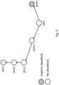
- FIG. 4 shows a deadlock graph or search tree for the example site of FIG. 1 , according to one example vehicle starting state for three vehicles.
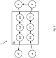
- FIG. 1 if three vehicles are positioned in nodes E, F and G there is a current deadlock situation, this is also called an explicit deadlock. None of the vehicles can move.
- a classifier informs the search tree of a state is an explicit deadlock or not.
- An example of such a deadlock classifier model can be found in the patent application EP22196693.0 from the same applicant. As can be seen, the states [AED2] and [B1EF] does not constitute an explicit deadlock.
- FIG. 5 shows a simplified graph or search tree according to FIG. 4 , after all explicit deadlocks for the starting position [AEF] have been identified.
- the graph or search tree can be simplified or pruned to only contain the states that will not lead to a deadlock as well as the first state that will ultimately lead to explicit deadlocks, i.e. a state with implicit deadlock is shown, in this example the state [B1EF].
- a state with implicit deadlock is shown, in this example the state [B1EF].
- vehicle trajectories can be more reliably identified offline, which when implemented reduce the likelihood of or completely avoid subsequent deadlocks.
- this allows the traffic planner to select actions to guide a set of vehicles along vehicle trajectories and/or to plan for a number of vehicles to follow the same trajectory whilst observing node occupancy constraints in a way that reduces reduce the likelihood of a deadlock occurring along any traffic-constrained areas long their trajectory/trajectories.
- FIG. 6 is a flowchart of an exemplary method 600 of assessing vehicle trajectories for deadlock scenarios in a site where multiple vehicles operate by following planned vehicle trajectories.
- the method 600 may comprise the following actions, steps or operations.
- the vehicles are reset to new start locations for a new calculation.
- the first and second classification memories, M_1 and M_2 may be different parts of the same memory or may be two separate memories that can be accessed by the computer-implemented traffic planner.
- the table below presents an example applying the method of the disclosure to site 1 of FIG. 1 : Table 1.
- Example application of the method of the disclosure Iteration Found deadlock Type Number of items in M_1 Number of items in M_2 Comment 1 E,F,D1 Explicit 1 0 2 E,F,C1 Implicit 1 1 At this state vehicle at F is not allowed to move due to the single lane of the traffic-constrained area. The only possible move of the vehicle at C1 will result into the explicit deadlock found in iteration 1. 3 E,F,D1 Implicit 1 2 Similar situation as above but the implicit deadlock found in iteration 2 blocks future movement of the vehicles.
- FIG. 7 shows an example of a traffic planner 700 including computer program code configured when executed to cause the traffic planner to implement the method shown schematically in FIG. 6 .
- the traffic planner 700 further comprises a memory 704, computer code 706 and one or more processor(s) or processing circuitry 708.
- the computer code when loaded from memory 704 and executed by the one or more processors or processing circuitry 708, causes the traffic planner 700 to perform the actions, steps or operations of the methods described above.
- the memory 704 may comprise the first and second classification memories, M_1 and M_2.
- the first and second classification memories, M_1 and M_2 may be one or two separate memories of the traffic planner 700.
- One or more data communication component(s) 702 may be provided for the traffic planner to enable communications with one or more remote entities. For example, in some embodiments a suitable receiver/transmitter/antenna arrangement is provided to communicate planned vehicle trajectories with one or more vehicles 100a-100c which form a planned fleet of vehicles intended to operate at a particular site or which are operating at a particular site to update the vehicles' planned vehicle trajectories at the site or defined region. The one or more data communication component(s) 702 may also be used to provide an alert when a deadlock has been identified by the method 600.
- the memory 702 stores computer program code 706 which, when loaded from the memory and executed by the one or more processor(s) or processing circuitry configures the traffic planner 700 to perform the disclosed method 600 for example.
- the computer program code 706 comprises a set of computer code modules M602-M612, which correspond to steps S602 to S612 shown in FIG. 6 .
- the computer-implemented traffic planner is configured for planning a plurality of planned vehicle trajectories for vehicles within a site according the examples above having at least one traffic-constrained area according the examples above.
- the traffic planner comprises a deadlock classifier model configured to classify a traffic situation for vehicle traffic following planned vehicle trajectories within the site.
- An example of such a deadlock classifier model can be found in the patent application EP22196693.0 from the same applicant.
- the deadlock classifier comprises first classification memory and a second classification memory wherein the traffic planner is configured, based on classifications generated by the method according to figure 6 , to populate the first classification memory with explicit deadlock states and the second classification memory with implicit deadlock states until all explicit and implicit deadlock states are found.
- the traffic planner is further configured, based on the stored explicit and implicit deadlock states in the first classification memory and the second classification memory, to plan an action to perform along each planned vehicle trajectory in the site.
- the action can for instance be to remain at the current node or to move forward to the next node.
- the traffic planner may further be configured, based on the stored explicit and implicit deadlock states in the first and second classification memories, to determine if a planned design of a site where multiple vehicles will operate by following planned vehicle trajectories will cause implicit and/or explicit deadlocks. In this way, vehicle trajectories for the site can already during planning to a great extent be laid out such that the risk of encountering deadlocks are removed or at least greatly reduced. Should the site need to be adapted over time, such as for instance due to a new phase in construction or due to expansion of a site such as a mine, harbour or warehouse, the traffic flow can already be planned in order for traffic to flow smoothly as soon as the adaptation of the site is finished.
- the traffic planner may be implemented on a stand-alone server or server system.
- the traffic planner is configured to assess a plurality of vehicle trajectories where a vehicle trajectory comprises a trajectory path, direction of travel, and action along the trajectory path in the direction of travel, for example, an action to pause at a particular segment of the trajectory, or to move to the next segment along the trajectory.
- a traffic planner for a site accordingly has the objective of planning how a plurality of vehicles should move or be guided along one or more trajectory paths in a site or similar defined area or region.
- the guided vehicle trajectories at a site are planned in a way that avoids deadlocks occurring to maximise their individual or fleet efficiency.
- vehicle trajectories that avoid deadlocks may allow vehicles at a site to function in a way that optimises their operational behaviour and fuel consumption, and ideally so that the site of operations as a whole is run efficiently.
- the traffic planner can calculate for each vehicle a vehicle trajectory that avoids a deadlock occurring within the planning horizon. In this way, the traffic planner may configure a plurality of vehicle trajectories within a site or similarly defined area where there may be one or more traffic-constrained areas or locations. The traffic planner may optimize the efficiency of the vehicle movements within the site to improve vehicle-related operations. For example, congestion at loading or unloading locations or at fueling sites can be avoided.
- FIG. 8 is a schematic diagram of a computer system 800 for implementing examples disclosed herein.
- the computer system 800 is adapted to execute instructions from a computer-readable medium to perform these and/or any of the functions or processing described herein.
- the computer system 800 may be connected (e.g., networked) to other machines in a LAN, an intranet, an extranet, or the Internet. While only a single device is illustrated, the computer system 800 may include any collection of devices that individually or jointly execute a set (or multiple sets) of instructions to perform any one or more of the methodologies discussed herein.
- any reference in the disclosure and/or claims to a computer system, computing system, computer device, computing device, control system, control unit, electronic control unit (ECU), processor device, processing circuitry, etc. includes reference to one or more such devices to individually or jointly execute a set (or multiple sets) of instructions to perform any one or more of the methodologies discussed herein.
- control system may include a single control unit or a plurality of control units connected or otherwise communicatively coupled to each other, such that any performed function may be distributed between the control units as desired.
- such devices may communicate with each other or other devices by various system architectures, such as directly or via a Controller Area Network (CAN) bus, etc.
- CAN Controller Area Network
- the computer system 800 may comprise at least one computing device or electronic device capable of including firmware, hardware, and/or executing software instructions to implement the functionality described herein.
- the computer system 800 may include processing circuitry 802 (e.g., processing circuitry including one or more processor devices or control units), a memory 804, and a system bus 806.
- the computer system 800 may include at least one computing device having the processing circuitry 802.
- the system bus 806 provides an interface for system components including, but not limited to, the memory 804 and the processing circuitry 802.
- the processing circuitry 802 may include any number of hardware components for conducting data or signal processing or for executing computer code stored in memory 804.
- the processing circuitry 802 may, for example, include a general-purpose processor, an application specific processor, a Digital Signal Processor (DSP), an Application Specific Integrated Circuit (ASIC), a Field Programmable Gate Array (FPGA), a circuit containing processing components, a group of distributed processing components, a group of distributed computers configured for processing, or other programmable logic device, discrete gate or transistor logic, discrete hardware components, or any combination thereof designed to perform the functions described herein.
- the processing circuitry 802 may further include computer executable code that controls operation of the programmable device.
- the system bus 806 may be any of several types of bus structures that may further interconnect to a memory bus (with or without a memory controller), a peripheral bus, and/or a local bus using any of a variety of bus architectures.
- the memory 804 may be one or more devices for storing data and/or computer code for completing or facilitating methods described herein.
- the memory 804 may include database components, object code components, script components, or other types of information structure for supporting the various activities herein. Any distributed or local memory device may be utilised with the systems and methods of this description.
- the memory 804 may be communicably connected to the processing circuitry 802 (e.g., via a circuit or any other wired, wireless, or network connection) and may include computer code for executing one or more processes described herein.
- the memory 804 may include non-volatile memory 808 (e.g., read-only memory (ROM), erasable programmable read-only memory (EPROM), electrically erasable programmable read-only memory (EEPROM), etc.), and volatile memory 810 (e.g., random-access memory (RAM)), or any other medium which can be used to carry or store desired program code in the form of machine-executable instructions or data structures and which can be accessed by a computer or other machine with processing circuitry 802.
- a basic input/output system (BIOS) 812 may be stored in the non-volatile memory 808 and can include the basic routines that help to transfer information between elements within the computer system 800.
- BIOS basic input/output system
- the computer system 800 may further include or be coupled to a non-transitory computer-readable storage medium such as the storage device 814, which may comprise, for example, an internal or external hard disk drive (HDD) (e.g., enhanced integrated drive electronics (EIDE) or serial advanced technology attachment (SATA)), HDD (e.g., EIDE or SATA) for storage, flash memory, or the like.
- HDD enhanced integrated drive electronics
- SATA serial advanced technology attachment
- the storage device 814 and other drives associated with computer-readable media and computer-usable media may provide non-volatile storage of data, data structures, computer-executable instructions, and the like.
- Computer-code that is hard or soft coded may be provided in the form of one or more modules.
- the module(s) can be implemented as software and/or hard-coded in circuitry to implement the functionality described herein in whole or in part.
- the modules may be stored in the storage device 814 and/or in the volatile memory 810, which may include an operating system 816 and/or one or more program modules 818.
- All or a portion of the examples disclosed herein may be implemented as a computer program 820 stored on a transitory or non-transitory computer-usable or computer-readable storage medium (e.g., single medium or multiple media), such as the storage device 814, which includes complex programming instructions (e.g., complex computer-readable program code) to cause the processing circuitry 802 to carry out actions described herein.
- the computer-readable program code of the computer program 820 can comprise software instructions for implementing the functionality of the examples described herein when executed by the processing circuitry 802.
- the storage device 814 may be a computer program product (e.g., readable storage medium) storing the computer program 820 thereon, where at least a portion of a computer program 820 may be loadable (e.g., into a processor) for implementing the functionality of the examples described herein when executed by the processing circuitry 802.
- the processing circuitry 802 may serve as a controller or control system for the computer system 800 that is to implement the functionality described herein.
- the computer system 800 may include an input device interface 822 configured to receive input and selections to be communicated to the computer system 800 when executing instructions, such as from a keyboard, mouse, touch-sensitive surface, etc. Such input devices may be connected to the processing circuitry 802 through the input device interface 822 coupled to the system bus 806 but can be connected through other interfaces, such as a parallel port, an Institute of Electrical and Electronic Engineers (IEEE) 1394 serial port, a Universal Serial Bus (USB) port, an IR interface, and the like.
- the computer system 800 may include an output device interface 824 configured to forward output, such as to a display, a video display unit (e.g., a liquid crystal display (LCD) or a cathode ray tube (CRT)).
- the computer system 800 may include a communications interface 826 suitable for communicating with a network as appropriate or desired.
- vehicle trajectories within a site are modelled and assessed to see if they will lead to a traffic deadlock at the site.
- the classification of each of the vehicle trajectories is made offline in a computer model of the site of interest and the output of the classifier is made available to the traffic planner when a candidate vehicle trajectory is being assessed by the traffic planner.
- the traffic planner may also respond dynamically to traffic situations as they occur on the site of interest, and it is possible in some embodiments to use the traffic planner to adjust vehicle trajectories in real-time by drawing on a set of guided vehicle trajectories that have been generated in advance and classified for that site as leading to a potential deadlock or not. This may allow dynamic adjustment of guided trajectories for one or more vehicles at a site in some embodiments.
- Example 1 A computer-implemented traffic planner according to the second aspect, wherein the vehicles are autonomous or manually operated heavy-duty vehicles following predetermined planned vehicle trajectories in the site.
- Example 2 A computer-implemented traffic planner according to the second aspect, wherein the site being a construction site, a mine, a harbour, a warehouse, an airport or a mass transit station.
- Relative terms such as “below” or “above” or “upper” or “lower” or “horisontal” or “vertical” may be used herein to describe a relationship of one element to another element as illustrated in the Figures. It will be understood that these terms and those discussed above are intended to encompass different orientations of the device in addition to the orientation depicted in the Figures. It will be understood that when an element is referred to as being “connected” or “coupled” to another element, it can be directly connected or coupled to the other element, or intervening elements may be present. In contrast, when an element is referred to as being “directly connected” or “directly coupled” to another element, there are no intervening elements present.
Landscapes
- Physics & Mathematics (AREA)
- General Physics & Mathematics (AREA)
- Chemical & Material Sciences (AREA)
- Analytical Chemistry (AREA)
- Engineering & Computer Science (AREA)
- Radar, Positioning & Navigation (AREA)
- Remote Sensing (AREA)
- Aviation & Aerospace Engineering (AREA)
- Automation & Control Theory (AREA)
- Traffic Control Systems (AREA)
Priority Applications (5)
| Application Number | Priority Date | Filing Date | Title |
|---|---|---|---|
| EP23173944.2A EP4465142B1 (fr) | 2023-05-17 | 2023-05-17 | Classificateur à blocage préventif |
| AU2024202280A AU2024202280A1 (en) | 2023-05-17 | 2024-04-10 | Preventive deadlock classifier |
| US18/638,083 US20240386794A1 (en) | 2023-05-17 | 2024-04-17 | Preventive deadlock classifier |
| PCT/EP2024/062759 WO2024235796A1 (fr) | 2023-05-17 | 2024-05-08 | Représentation d'ensemble de données de blocage de trafic pour une classification de blocage efficace par calcul |
| EP24725463.4A EP4713750A1 (fr) | 2023-05-17 | 2024-05-08 | Représentation d'ensemble de données de blocage de trafic pour une classification de blocage efficace par calcul |
Applications Claiming Priority (1)
| Application Number | Priority Date | Filing Date | Title |
|---|---|---|---|
| EP23173944.2A EP4465142B1 (fr) | 2023-05-17 | 2023-05-17 | Classificateur à blocage préventif |
Publications (2)
| Publication Number | Publication Date |
|---|---|
| EP4465142A1 true EP4465142A1 (fr) | 2024-11-20 |
| EP4465142B1 EP4465142B1 (fr) | 2025-07-30 |
Family
ID=86387229
Family Applications (1)
| Application Number | Title | Priority Date | Filing Date |
|---|---|---|---|
| EP23173944.2A Active EP4465142B1 (fr) | 2023-05-17 | 2023-05-17 | Classificateur à blocage préventif |
Country Status (3)
| Country | Link |
|---|---|
| US (1) | US20240386794A1 (fr) |
| EP (1) | EP4465142B1 (fr) |
| AU (1) | AU2024202280A1 (fr) |
Families Citing this family (1)
| Publication number | Priority date | Publication date | Assignee | Title |
|---|---|---|---|---|
| US20250033674A1 (en) * | 2023-07-26 | 2025-01-30 | Gm Cruise Holdings Llc | Multi-vehicle remote assistance |
-
2023
- 2023-05-17 EP EP23173944.2A patent/EP4465142B1/fr active Active
-
2024
- 2024-04-10 AU AU2024202280A patent/AU2024202280A1/en active Pending
- 2024-04-17 US US18/638,083 patent/US20240386794A1/en active Pending
Non-Patent Citations (2)
| Title |
|---|
| DRAGANJAC IVICA ET AL: "Highly-scalable traffic management of autonomous industrial transportation systems", ROBOTICS AND COMPUTER INTEGRATED MANUFACTURING, ELSEVIER SCIENCE PUBLISHERS BV., BARKING, GB, vol. 63, 13 December 2019 (2019-12-13), XP086019179, ISSN: 0736-5845, [retrieved on 20191213], DOI: 10.1016/J.RCIM.2019.101915 * |
| SVESTKA P ET AL: "Coordinated path planning for multiple robots", ROBOTICS AND AUTONOMOUS SYSTEMS, ELSEVIER BV, AMSTERDAM, NL, vol. 23, no. 3, 2 April 1998 (1998-04-02), pages 125 - 152, XP004122375, ISSN: 0921-8890, DOI: 10.1016/S0921-8890(97)00033-X * |
Also Published As
| Publication number | Publication date |
|---|---|
| EP4465142B1 (fr) | 2025-07-30 |
| US20240386794A1 (en) | 2024-11-21 |
| AU2024202280A1 (en) | 2024-12-05 |
Similar Documents
| Publication | Publication Date | Title |
|---|---|---|
| US10423934B1 (en) | Automated vehicle diagnostics and maintenance | |
| US12051325B2 (en) | Method and apparatus for coordinating multiple cooperative vehicle trajectories on shared road networks | |
| US20180292830A1 (en) | Automatic Tuning of Autonomous Vehicle Cost Functions Based on Human Driving Data | |
| CA2983725C (fr) | Installation de production, procede de conception d'installation de production, procede de commande d'installation de production et procede de fabrication | |
| CN115092141B (zh) | 应用于自动驾驶车辆变道超车的轨迹规划方法及设备 | |
| US20240386794A1 (en) | Preventive deadlock classifier | |
| CN104133471A (zh) | 无人驾驶运输车辆及运行方法,包括该无人驾驶运输车辆的系统及规划虚拟轨迹的方法 | |
| US20250076877A1 (en) | Deadlock prediction for traffic planning | |
| US20250091616A1 (en) | Method and computer system for multi-level control of motion actuators in an autonomous vehicle | |
| CN108229730A (zh) | 一种基于模糊奖励的无人驾驶车辆轨迹生成方法 | |
| Hoogendoorn et al. | Modeling driver, driver support, and cooperative systems with dynamic optimal control | |
| TWI702377B (zh) | 一種管理複數交通工具之方法、系統、儲存媒體與伺服器 | |
| EP4462404B1 (fr) | Procédé de planification de trafic pour une flotte de véhicules | |
| US20230070734A1 (en) | Method and system for configuring variations in autonomous vehicle training simulations | |
| EP4564326A1 (fr) | Système et procédé de commande de mouvements de véhicules | |
| EP4465141A1 (fr) | Représentation d'ensemble de données d'interblocage de trafic pour classification d'interblocage efficace du point de vue du calcul | |
| US20250118207A1 (en) | System and method of controlling movements of vehicles | |
| WO2023009925A1 (fr) | Procédé et système de configuration de variations dans des simulations d'entraînement de véhicule autonomes | |
| EP4386709A1 (fr) | Décalages longitudinaux en un trajet prédéfini | |
| Li | Task Assignment and Path Planning for Autonomous Mobile Robots in Stochastic Warehouse Systems | |
| EP4713750A1 (fr) | Représentation d'ensemble de données de blocage de trafic pour une classification de blocage efficace par calcul | |
| EP4466429B1 (fr) | Systèmes et procédés de stationnement pour agencer des véhicules à l'intérieur d'un garage de stationnement | |
| EP4390598A1 (fr) | Gestion de véhicules automatisés dans une zone désignée grâce à des robots terrestres configurés comme capteurs mobiles | |
| US20240249221A1 (en) | Method for constructing a goods logistics facility, computer-readable storage medium, and goods logistics facility | |
| EP4466428B1 (fr) | Systèmes et procédés de stationnement pour préconfigurer des aires pour réduire le temps de récupération de véhicule |
Legal Events
| Date | Code | Title | Description |
|---|---|---|---|
| PUAI | Public reference made under article 153(3) epc to a published international application that has entered the european phase |
Free format text: ORIGINAL CODE: 0009012 |
|
| STAA | Information on the status of an ep patent application or granted ep patent |
Free format text: STATUS: THE APPLICATION HAS BEEN PUBLISHED |
|
| AK | Designated contracting states |
Kind code of ref document: A1 Designated state(s): AL AT BE BG CH CY CZ DE DK EE ES FI FR GB GR HR HU IE IS IT LI LT LU LV MC ME MK MT NL NO PL PT RO RS SE SI SK SM TR |
|
| STAA | Information on the status of an ep patent application or granted ep patent |
Free format text: STATUS: REQUEST FOR EXAMINATION WAS MADE |
|
| 17P | Request for examination filed |
Effective date: 20241219 |
|
| REG | Reference to a national code |
Ref legal event code: R079 Free format text: PREVIOUS MAIN CLASS: G05D0001020000 Ipc: G05D0001693000 Ref country code: DE Ref legal event code: R079 Ref document number: 602023005144 Country of ref document: DE Free format text: PREVIOUS MAIN CLASS: G05D0001020000 Ipc: G05D0001693000 |
|
| RIC1 | Information provided on ipc code assigned before grant |
Ipc: G08G 1/01 20060101ALI20250327BHEP Ipc: G05D 109/10 20240101ALI20250327BHEP Ipc: G05D 105/28 20240101ALI20250327BHEP Ipc: G05D 1/693 20240101AFI20250327BHEP |
|
| GRAP | Despatch of communication of intention to grant a patent |
Free format text: ORIGINAL CODE: EPIDOSNIGR1 |
|
| STAA | Information on the status of an ep patent application or granted ep patent |
Free format text: STATUS: GRANT OF PATENT IS INTENDED |
|
| INTG | Intention to grant announced |
Effective date: 20250507 |
|
| GRAS | Grant fee paid |
Free format text: ORIGINAL CODE: EPIDOSNIGR3 |
|
| GRAA | (expected) grant |
Free format text: ORIGINAL CODE: 0009210 |
|
| STAA | Information on the status of an ep patent application or granted ep patent |
Free format text: STATUS: THE PATENT HAS BEEN GRANTED |
|
| AK | Designated contracting states |
Kind code of ref document: B1 Designated state(s): AL AT BE BG CH CY CZ DE DK EE ES FI FR GB GR HR HU IE IS IT LI LT LU LV MC ME MK MT NL NO PL PT RO RS SE SI SK SM TR |
|
| REG | Reference to a national code |
Ref country code: GB Ref legal event code: FG4D |
|
| REG | Reference to a national code |
Ref country code: CH Ref legal event code: EP |
|
| REG | Reference to a national code |
Ref country code: DE Ref legal event code: R096 Ref document number: 602023005144 Country of ref document: DE |
|
| REG | Reference to a national code |
Ref country code: IE Ref legal event code: FG4D |
|
| REG | Reference to a national code |
Ref country code: SE Ref legal event code: TRGR |
|
| REG | Reference to a national code |
Ref country code: NL Ref legal event code: MP Effective date: 20250730 |
|
| REG | Reference to a national code |
Ref country code: AT Ref legal event code: MK05 Ref document number: 1819640 Country of ref document: AT Kind code of ref document: T Effective date: 20250730 |
|
| PG25 | Lapsed in a contracting state [announced via postgrant information from national office to epo] |
Ref country code: PT Free format text: LAPSE BECAUSE OF FAILURE TO SUBMIT A TRANSLATION OF THE DESCRIPTION OR TO PAY THE FEE WITHIN THE PRESCRIBED TIME-LIMIT Effective date: 20251202 |
|
| PG25 | Lapsed in a contracting state [announced via postgrant information from national office to epo] |
Ref country code: IS Free format text: LAPSE BECAUSE OF FAILURE TO SUBMIT A TRANSLATION OF THE DESCRIPTION OR TO PAY THE FEE WITHIN THE PRESCRIBED TIME-LIMIT Effective date: 20251130 |
|
| PG25 | Lapsed in a contracting state [announced via postgrant information from national office to epo] |
Ref country code: NO Free format text: LAPSE BECAUSE OF FAILURE TO SUBMIT A TRANSLATION OF THE DESCRIPTION OR TO PAY THE FEE WITHIN THE PRESCRIBED TIME-LIMIT Effective date: 20251030 |
|
| REG | Reference to a national code |
Ref country code: LT Ref legal event code: MG9D |
|
| PG25 | Lapsed in a contracting state [announced via postgrant information from national office to epo] |
Ref country code: AT Free format text: LAPSE BECAUSE OF FAILURE TO SUBMIT A TRANSLATION OF THE DESCRIPTION OR TO PAY THE FEE WITHIN THE PRESCRIBED TIME-LIMIT Effective date: 20250730 |
|
| PG25 | Lapsed in a contracting state [announced via postgrant information from national office to epo] |
Ref country code: FI Free format text: LAPSE BECAUSE OF FAILURE TO SUBMIT A TRANSLATION OF THE DESCRIPTION OR TO PAY THE FEE WITHIN THE PRESCRIBED TIME-LIMIT Effective date: 20250730 |
|
| PG25 | Lapsed in a contracting state [announced via postgrant information from national office to epo] |
Ref country code: HR Free format text: LAPSE BECAUSE OF FAILURE TO SUBMIT A TRANSLATION OF THE DESCRIPTION OR TO PAY THE FEE WITHIN THE PRESCRIBED TIME-LIMIT Effective date: 20250730 Ref country code: NL Free format text: LAPSE BECAUSE OF FAILURE TO SUBMIT A TRANSLATION OF THE DESCRIPTION OR TO PAY THE FEE WITHIN THE PRESCRIBED TIME-LIMIT Effective date: 20250730 |
|
| PG25 | Lapsed in a contracting state [announced via postgrant information from national office to epo] |
Ref country code: GR Free format text: LAPSE BECAUSE OF FAILURE TO SUBMIT A TRANSLATION OF THE DESCRIPTION OR TO PAY THE FEE WITHIN THE PRESCRIBED TIME-LIMIT Effective date: 20251031 |
|
| PG25 | Lapsed in a contracting state [announced via postgrant information from national office to epo] |
Ref country code: LV Free format text: LAPSE BECAUSE OF FAILURE TO SUBMIT A TRANSLATION OF THE DESCRIPTION OR TO PAY THE FEE WITHIN THE PRESCRIBED TIME-LIMIT Effective date: 20250730 |
|
| PG25 | Lapsed in a contracting state [announced via postgrant information from national office to epo] |
Ref country code: PL Free format text: LAPSE BECAUSE OF FAILURE TO SUBMIT A TRANSLATION OF THE DESCRIPTION OR TO PAY THE FEE WITHIN THE PRESCRIBED TIME-LIMIT Effective date: 20250730 Ref country code: BG Free format text: LAPSE BECAUSE OF FAILURE TO SUBMIT A TRANSLATION OF THE DESCRIPTION OR TO PAY THE FEE WITHIN THE PRESCRIBED TIME-LIMIT Effective date: 20250730 |
|
| PG25 | Lapsed in a contracting state [announced via postgrant information from national office to epo] |
Ref country code: RS Free format text: LAPSE BECAUSE OF FAILURE TO SUBMIT A TRANSLATION OF THE DESCRIPTION OR TO PAY THE FEE WITHIN THE PRESCRIBED TIME-LIMIT Effective date: 20251030 |
|
| PG25 | Lapsed in a contracting state [announced via postgrant information from national office to epo] |
Ref country code: ES Free format text: LAPSE BECAUSE OF FAILURE TO SUBMIT A TRANSLATION OF THE DESCRIPTION OR TO PAY THE FEE WITHIN THE PRESCRIBED TIME-LIMIT Effective date: 20250730 |
|
| PG25 | Lapsed in a contracting state [announced via postgrant information from national office to epo] |
Ref country code: SM Free format text: LAPSE BECAUSE OF FAILURE TO SUBMIT A TRANSLATION OF THE DESCRIPTION OR TO PAY THE FEE WITHIN THE PRESCRIBED TIME-LIMIT Effective date: 20250730 |
|
| PG25 | Lapsed in a contracting state [announced via postgrant information from national office to epo] |
Ref country code: DK Free format text: LAPSE BECAUSE OF FAILURE TO SUBMIT A TRANSLATION OF THE DESCRIPTION OR TO PAY THE FEE WITHIN THE PRESCRIBED TIME-LIMIT Effective date: 20250730 |
|
| PG25 | Lapsed in a contracting state [announced via postgrant information from national office to epo] |
Ref country code: IT Free format text: LAPSE BECAUSE OF FAILURE TO SUBMIT A TRANSLATION OF THE DESCRIPTION OR TO PAY THE FEE WITHIN THE PRESCRIBED TIME-LIMIT Effective date: 20250730 |
|
| PG25 | Lapsed in a contracting state [announced via postgrant information from national office to epo] |
Ref country code: CZ Free format text: LAPSE BECAUSE OF FAILURE TO SUBMIT A TRANSLATION OF THE DESCRIPTION OR TO PAY THE FEE WITHIN THE PRESCRIBED TIME-LIMIT Effective date: 20250730 |
|
| PG25 | Lapsed in a contracting state [announced via postgrant information from national office to epo] |
Ref country code: SK Free format text: LAPSE BECAUSE OF FAILURE TO SUBMIT A TRANSLATION OF THE DESCRIPTION OR TO PAY THE FEE WITHIN THE PRESCRIBED TIME-LIMIT Effective date: 20250730 Ref country code: EE Free format text: LAPSE BECAUSE OF FAILURE TO SUBMIT A TRANSLATION OF THE DESCRIPTION OR TO PAY THE FEE WITHIN THE PRESCRIBED TIME-LIMIT Effective date: 20250730 |