EP4466979A2 - Tambour hacheur pour une récolteuse-hacheuse - Google Patents
Tambour hacheur pour une récolteuse-hacheuse Download PDFInfo
- Publication number
- EP4466979A2 EP4466979A2 EP24161491.6A EP24161491A EP4466979A2 EP 4466979 A2 EP4466979 A2 EP 4466979A2 EP 24161491 A EP24161491 A EP 24161491A EP 4466979 A2 EP4466979 A2 EP 4466979A2
- Authority
- EP
- European Patent Office
- Prior art keywords
- carrier element
- rotation
- fixing
- cutting
- carrier
- Prior art date
- Legal status (The legal status is an assumption and is not a legal conclusion. Google has not performed a legal analysis and makes no representation as to the accuracy of the status listed.)
- Pending
Links
- 239000004459 forage Substances 0.000 title claims abstract description 12
- 238000005520 cutting process Methods 0.000 claims abstract description 116
- 238000000034 method Methods 0.000 claims description 7
- 238000004519 manufacturing process Methods 0.000 claims description 4
- 238000003754 machining Methods 0.000 description 8
- 238000013459 approach Methods 0.000 description 3
- 230000005540 biological transmission Effects 0.000 description 3
- 238000010521 absorption reaction Methods 0.000 description 2
- 239000011796 hollow space material Substances 0.000 description 2
- 238000009434 installation Methods 0.000 description 2
- 239000000463 material Substances 0.000 description 2
- 238000005058 metal casting Methods 0.000 description 2
- 239000007787 solid Substances 0.000 description 2
- 238000003466 welding Methods 0.000 description 2
- 239000000956 alloy Substances 0.000 description 1
- 229910045601 alloy Inorganic materials 0.000 description 1
- 238000011161 development Methods 0.000 description 1
- 230000018109 developmental process Effects 0.000 description 1
- 230000000694 effects Effects 0.000 description 1
- 238000005304 joining Methods 0.000 description 1
- 239000002184 metal Substances 0.000 description 1
- 230000000284 resting effect Effects 0.000 description 1
- 238000007493 shaping process Methods 0.000 description 1
Images






Classifications
-
- A—HUMAN NECESSITIES
- A01—AGRICULTURE; FORESTRY; ANIMAL HUSBANDRY; HUNTING; TRAPPING; FISHING
- A01F—PROCESSING OF HARVESTED PRODUCE; HAY OR STRAW PRESSES; DEVICES FOR STORING AGRICULTURAL OR HORTICULTURAL PRODUCE
- A01F29/00—Cutting apparatus specially adapted for cutting hay, straw or the like
- A01F29/06—Cutting apparatus specially adapted for cutting hay, straw or the like having rotating knives with their cutting edges on a cylinder surface, e.g. of the helical-type
-
- A—HUMAN NECESSITIES
- A01—AGRICULTURE; FORESTRY; ANIMAL HUSBANDRY; HUNTING; TRAPPING; FISHING
- A01F—PROCESSING OF HARVESTED PRODUCE; HAY OR STRAW PRESSES; DEVICES FOR STORING AGRICULTURAL OR HORTICULTURAL PRODUCE
- A01F29/00—Cutting apparatus specially adapted for cutting hay, straw or the like
- A01F29/09—Details
- A01F29/095—Mounting or adjusting of knives
-
- A—HUMAN NECESSITIES
- A01—AGRICULTURE; FORESTRY; ANIMAL HUSBANDRY; HUNTING; TRAPPING; FISHING
- A01F—PROCESSING OF HARVESTED PRODUCE; HAY OR STRAW PRESSES; DEVICES FOR STORING AGRICULTURAL OR HORTICULTURAL PRODUCE
- A01F29/00—Cutting apparatus specially adapted for cutting hay, straw or the like
- A01F29/09—Details
- A01F29/16—Safety devices, e.g. emergency brake arrangements
-
- B—PERFORMING OPERATIONS; TRANSPORTING
- B02—CRUSHING, PULVERISING, OR DISINTEGRATING; PREPARATORY TREATMENT OF GRAIN FOR MILLING
- B02C—CRUSHING, PULVERISING, OR DISINTEGRATING IN GENERAL; MILLING GRAIN
- B02C18/00—Disintegrating by knives or other cutting or tearing members which chop material into fragments
- B02C18/06—Disintegrating by knives or other cutting or tearing members which chop material into fragments with rotating knives
- B02C18/14—Disintegrating by knives or other cutting or tearing members which chop material into fragments with rotating knives within horizontal containers
- B02C18/144—Disintegrating by knives or other cutting or tearing members which chop material into fragments with rotating knives within horizontal containers with axially elongated knives
-
- B—PERFORMING OPERATIONS; TRANSPORTING
- B02—CRUSHING, PULVERISING, OR DISINTEGRATING; PREPARATORY TREATMENT OF GRAIN FOR MILLING
- B02C—CRUSHING, PULVERISING, OR DISINTEGRATING IN GENERAL; MILLING GRAIN
- B02C18/00—Disintegrating by knives or other cutting or tearing members which chop material into fragments
- B02C18/06—Disintegrating by knives or other cutting or tearing members which chop material into fragments with rotating knives
- B02C18/16—Details
- B02C18/18—Knives; Mountings thereof
- B02C18/186—Axially elongated knives
-
- B—PERFORMING OPERATIONS; TRANSPORTING
- B02—CRUSHING, PULVERISING, OR DISINTEGRATING; PREPARATORY TREATMENT OF GRAIN FOR MILLING
- B02C—CRUSHING, PULVERISING, OR DISINTEGRATING IN GENERAL; MILLING GRAIN
- B02C2201/00—Codes relating to disintegrating devices adapted for specific materials
- B02C2201/06—Codes relating to disintegrating devices adapted for specific materials for garbage, waste or sewage
- B02C2201/066—Codes relating to disintegrating devices adapted for specific materials for garbage, waste or sewage for garden waste
Definitions
- the invention relates to a chopper drum for a forage harvester.
- the chopper drum is designed to rotate in a direction of rotation around an axis of rotation.
- the chopper drum has an input shaft and a hollow shaft arranged in a fixed position relative to the input shaft.
- the chopper drum also has at least one first fixing element.
- the first fixing element is arranged at least among other things on an outer surface of the hollow shaft and extends in the direction of rotation.
- the chopper drum also has a first carrier element.
- the first carrier element is detachably attached to the first fixing element.
- a first cutting element is arranged on the first carrier element, which has a cutting edge for cutting crops, which extends over the first fixing element at an angle to the direction of rotation in a radial view.
- the chopper drum also has a second carrier element.
- the second carrier element is detachably attached to the first fixing element.
- a second cutting element adjacent to the first cutting element in the direction of rotation is arranged on the second carrier element.
- the second cutting element has a cutting edge for cutting crops, which extends over the first fixing element at an angle to the direction of rotation in the radial view.
- the chopper drum is basically used to chop up the crop. To do this, the chopper drum rotates around the axis of rotation while the crop is moved towards it. The cutting elements cut a portion of the crop fed in per revolution. It has been shown that for field choppers with the crop throughputs required today, sufficient rigidity of the chopper drum can only be ensured by using the hollow shaft.
- a previously described chopping drum is from the DE 10 2012 023 431 A1
- the carrier elements are formed by ring segments that are adjacent to one another and are placed on the fixing element in an axial direction relative to the axis of rotation.
- the known chopping drum is disadvantageous, especially in unintentional collision of one of the cutting elements with an object that is not to be cut, which occurs repeatedly during operation.
- the colliding cutting element deforms the carrier element on which it is arranged, which in turn necessarily deforms the adjacent carrier element.
- Such collisions occur relatively frequently with the known chopper drum, since the cutting elements are only supported at certain points along their length by the existing carrier elements and are relatively unstable in between.
- both carrier elements means that at least both carrier elements and the cutting elements arranged on them must then be replaced in order to repair the chopper drum, which, in addition to considerable material costs, is also time-consuming and means unintentional downtime for the forage harvester.
- the object of the present invention is to improve the chopper drum in such a way that the downtime of the forage harvester caused by damage to the chopper drum is reduced. It is also the object of the invention to develop a method for producing such an improved chopper drum.
- the first object is achieved in that the first carrier element is spaced apart from the second carrier element in the direction of rotation.
- the two carrier elements have no contact with each other.
- a collision of the first cutting element is accompanied by an unavoidable deformation of the first carrier element.
- this deformation has no effect on the second carrier element. Therefore, to repair the chopper drum, only the first carrier element needs to be replaced with the first cutting element, which means that the downtime of the forage harvester can be significantly reduced compared to the prior art.
- the input shaft of the chopping drum is used to absorb a torque from a drive means such as a belt.
- the input shaft is arranged at least partially axially offset from the hollow shaft.
- the input shaft is in particular at least partially designed as a solid shaft, wherein the diameter of the hollow shaft is at least a multiple of the diameter of the solid shaft.
- the input shaft is arranged directly on the hollow shaft or is connected to the hollow shaft by means of another component of the chopping drum.
- the hollow shaft is immobile relative to the input shaft.
- the input shaft is connected to the hollow shaft or the component in a detachable or non-detachable manner.
- the input shaft can be formed as one piece with the hollow shaft or the component.
- the hollow shaft is designed in particular as a drum body.
- An axis of symmetry of the hollow shaft corresponds to the axis of rotation.
- the axis of rotation is a geometric axis, not an actual axis.
- the hollow shaft is preferably hollow over at least a predominant part of its length, in particular over its entire length.
- a cross-sectional area of the hollow shaft is preferably unchangeable in the axial direction.
- the outer surface is preferably designed in the shape of a cylinder jacket.
- the hollow shaft is understood to be a component independent of any other components of the chopping drum, which are arranged on the hollow shaft after the hollow shaft has been formed in a detachable or non-detachable manner, i.e. in particular cannot be separated from the hollow shaft without causing damage. This applies in particular with regard to the fixing element.
- the outer diameter of the hollow shaft preferably corresponds to at least one third of the outer diameter of the entire chopping drum.
- the fixing element is preferably welded onto the hollow shaft. It extends in particular in the direction of rotation such that its main direction of extension is the direction of rotation.
- the fixing element preferably lies seamlessly against the hollow shaft along its entire extension in the direction of rotation.
- the fixing element is preferably ring-shaped or ring-segment-shaped. In the case of a ring-shaped design, the fixing element is optionally designed in several parts. In the case of a ring-segment-shaped design, in particular several ring-segment-shaped fixing elements adjoin one another in the direction of rotation in order to jointly form the ring shape.
- the ring shape means in particular that in a cross-section through the fixing element, the space within the hollow shaft is free from
- the fixing element is preferably a metal casting, particularly preferably made of a directly weldable alloy.
- the carrier elements preferably lie directly on the fixing element.
- the detachable fastening of the carrier elements makes it possible to repair the chopping drum by replacing individual parts after a collision, whereas a chopping drum with welded carrier elements usually has to be replaced in its entirety after a collision.
- the carrier elements are arranged at a distance from the hollow shaft.
- the carrier elements are preferably screwed to the fixing element.
- the carrier elements are preferably drawn metal profiles.
- the carrier elements are preferably identical.
- the chopping drum does not have a carrier element equipped with a cutting element that is not detachably fastened.
- the position of the second carrier element differs from the position of the first carrier element preferably only by pivoting about the axis of rotation.
- the first and second carrier elements are therefore spaced apart from one another in the direction of rotation.
- the carrier elements are preferably arranged adjacent to one another in the direction of rotation.
- No further carrier element is arranged between the first carrier element and the second carrier element, at least in relation to the direction of rotation.
- the cutting elements are in particular knives.
- the first cutting element and the second cutting element are in particular identical in design.
- the cutting elements are preferably screwed to the respective carrier element.
- no further cutting element is arranged between the first cutting element and the second cutting element in relation to the direction of rotation.
- the cross-sectional area of the cutting elements preferably extends partly tangentially and partly radially elongated and ends in their respective cutting edge.
- the blades work together with a counter blade that is immovable relative to the axis of rotation.
- the crop is cut in the manner of a scissor cut between one of the blades and the counter blade.
- the blades define the outer diameter of the chopping drum.
- each point on the blade is at a constant distance from the axis of rotation.
- each point of the cutting edge lies in an imaginary cylindrical surface or conical surface related to the axis of rotation.
- the cutting edge is preferably angled to the axial direction and/or spiral-shaped around the axis of rotation.
- the first cutting element and the second cutting element belong to a first set of cutting elements which are cut in the cross-section mentioned.
- the first set of cutting elements preferably has a total of 18 cutting elements.
- the chopping drum preferably has a second set of cutting elements which is arranged offset in the axial direction from the first set and is basically of the same design.
- the second set is particularly preferably mirrored on a mirror plane perpendicular to the axis of rotation and arranged pivoted about the axis of rotation.
- Directional, perspective and other axis-related information are generally to be understood as referring to the axis of rotation.
- the radial view is to be understood in such a way that the viewing direction is parallel to a radial, i.e. the chopper drum is viewed at right angles to the axis of rotation.
- the chopping drum according to the invention is in particular part of a forage harvester according to the invention.
- the forage harvester has a chassis and a driver's cab.
- the forage harvester also has a receiving device for receiving plants as harvested crops and an ejection device for ejecting the chopped crops.
- the first carrier element is detachably attached to a second fixing element.
- the second fixing element is at least partially spaced apart in the axial direction from the first fixing element.
- the second fixing element is arranged at least among other things on the outer surface of the hollow shaft and the second fixing element extends in the circumferential direction.
- the first carrier element extends in the axial direction from the first to the second fixing element and is in particular screwed to both fixing elements.
- the cutting edge of the first cutting element preferably extends in the radial view over both Fixing elements.
- the fixing elements are preferably similar at least in terms of their surface facing away from the axis of rotation and/or in terms of their axial extent.
- first and the second fixing element there is in particular a hollow space which is bordered in the radial direction by the first carrier element and the hollow shaft.
- the first carrier element is particularly preferably detachably attached to a third fixing element.
- the third fixing element is arranged in the axial direction between the first fixing element and the second fixing element, from which it is at least partially spaced in the axial direction.
- the third fixing element is arranged at least among other things on the outer surface of the hollow shaft and extends in the direction of rotation.
- the geometry of the third fixing element corresponds in particular to the geometry of the second fixing element.
- the third fixing element further increases the stability of the first carrier element relative to the hollow shaft and thus also the stability of the first cutting element.
- the first fixing element and the second fixing element and in particular the third fixing element form a fixing element group for supporting the first group of cutting elements.
- the chopping drum preferably comprises a second similarly designed fixing element group which is offset in the axial direction, in particular mirrored, and serves to support the second group of cutting elements.
- the first carrier element extends longitudinally parallel to the cutting edge of the first cutting element.
- the longitudinal extension is to be understood such that the main extension direction of the carrier element coincides with the extension direction of the cutting edge.
- the main extension direction has an axial and a tangential component.
- the length of the first carrier element is in particular at least substantially equal to the length of the first cutting element.
- the length of a contact surface between the first carrier element and the first cutting element preferably corresponds to the length of the first carrier element.
- the first carrier element is screwed to at least the first fixing element by means of a screw.
- the screw rotation axis is preferably arranged at right angles to the main direction of extension of the first carrier element.
- the screw rotation axis does not intersect the rotation axis, so that a longer and thus more resilient screw can be used without increasing the diameter of the chopping drum.
- the first carrier element is screwed to one screw per fixing element (of the respective fixing element group). This alignment of the screw allows the forces generated during operation to be transferred to the at least one fixing element to a particularly large extent.
- the screw rotation axis can be arranged in an axial plane perpendicular to the rotation axis.
- each cutting element is carried by exactly one carrier element. This ensures that in the event of a collision of one of the cutting elements, only one of the carrier elements is directly affected and necessarily needs to be replaced.
- each carrier element carries exactly one cutting element. This ensures that in the event of a collision of one of the cutting elements, further cutting elements do not necessarily need to be dismantled and the carrier element that needs to be replaced is as small as possible.
- each cutting element forms a cutting unit with the carrier element that carries the cutting element.
- the first fixing element has a first carrier element contact surface against which the first carrier element rests.
- the second fixing element has a second carrier element contact surface against which the first carrier element rests.
- the first carrier element contact surface is relative to the second carrier element contact surface offset in the direction of rotation, in particular pivoted about the axis of rotation.
- the first carrier element preferably rests with the same side or surface on the first and second carrier element contact surface. The positioning of the carrier element contact surfaces relative to one another ensures that the first carrier element can be formed with at least essentially a constant thickness along its entire length, which ensures a homogeneous transmission of forces to the fixing elements.
- the carrier element contact surfaces preferably have an identical shape.
- the first carrier element contact surface extends in particular proportionately in the axial direction. In a cross-section perpendicular to the axis of rotation, the first carrier element contact surface is angled to a radial that intersects the first carrier element contact surface in such a way that the first carrier element contact surface approaches the axis of rotation from a first contact surface end of the first carrier element contact surface. Particularly preferably, the first carrier element contact surface approaches the axis of rotation from the first contact surface end to a second contact surface end of the first carrier element contact surface.
- the first carrier element contact surface is in particular free of corners or angles in the cross-section and preferably deviates in a straight line from a tangent intersecting the first carrier element contact surface.
- the approximation described is to be understood in particular apart from any grooves extending parallel to the cutting edge of the first cutting element.
- the first carrier element contact surface angled in this way enables improved force transmission from the first carrier element to the first fixing element and thus reduces the probability of contact between the first and second carrier elements in the event of a collision.
- the screw rotation axis is preferably positioned at least locally at right angles to the first carrier element contact surface.
- the second contact surface end is arranged in front of the first contact surface end in relation to the direction of rotation.
- the first fixing element pushes the first carrier element in the direction of rotation during operation.
- the contact surface end is in particular, not only the outermost point of the first carrier element contact surface in the cross-section is to be understood, but also an end region of the first carrier element contact surface.
- the input shaft is preferably arranged on an input shaft contact surface of a torque receiving section of the first fixing element.
- the input shaft is preferably only arranged on the first fixing element and not on the hollow shaft.
- the input shaft contact surface is in particular formed at right angles to the axis of rotation.
- the input shaft is preferably screwed to the first fixing element. This arrangement of the input shaft allows weld seams to be reduced and in particular makes a shaft torque receiving section that has to be welded into the hollow space of the hollow shaft superfluous.
- the input shaft preferably comprises a torque output element designed as a flange that rests on the input shaft contact surface.
- the chopping drum has a further fixing element with a further input shaft contact surface on which the input shaft is additionally arranged.
- the torque receiving section or the input shaft contact surface preferably has a smaller inner diameter than the hollow shaft. This ensures that the torque is transmitted from the input shaft to the first fixing element in a diameter range that is below the inner diameter of the hollow shaft and thus reduces the installation space of the input shaft.
- the torque receiving section or the input shaft contact surface is arranged offset in the axial direction from the hollow shaft.
- the first fixing element therefore extends in a longitudinal section through the hollow shaft along its front side in the direction of the axis of rotation. This allows the installation space required by the chopping drum to be reduced.
- the first fixing element is to be pushed onto the hollow shaft, in particular in the axial direction, to implement the two features mentioned above, until the torque receiving section abuts the front side of the hollow shaft.
- the torque receiving section preferably has a central bore in the direction of the axis of rotation, through which the input shaft particularly preferably extends.
- first carrier element preferably also to be understood with reference to the second carrier element or all carrier elements.
- first fixing element in particular the first carrier element contact surface
- second/third fixing element in particular the second carrier element contact surface, or all fixing elements, in particular carrier element contact surfaces.
- the second object is achieved by a method for producing a chopper drum for a forage harvester.
- the method is used in particular for producing a chopper drum as described above and/or below.
- at least one fixing element is first attached to an outer surface of a hollow shaft.
- the fixing element is in particular welded to the hollow shaft.
- the fixing element is then at least partially machined.
- the fixing element is in particular milled.
- at least one carrier element is detachably attached to the fixing element.
- the carrier element is in particular screwed to the fixing element.
- a cutting element with a cutting edge is arranged on the carrier element independently of the aforementioned steps.
- the fixing element is machined to produce a carrier element contact surface, to which the carrier element is placed before it is detachably fastened.
- the carrier element contact surface is decisive for the positioning of the cutting element.
- the carrier element contact surface is of essential It is important to set the correct distance between the cutting edge and the rotation axis. If the distance between the cutting edge and the rotation axis is too great, the risk of collision is greatly increased. In this respect, the machining of the carrier element contact surface after joining the fixing element is of great importance for avoiding collisions.
- the exact positioning of the cutting elements is also advantageous because it allows grinding of the cutting edges to be shortened and limited to a minimum amount of material removal.
- the fixing element is machined to produce an input shaft contact surface of a torque-receiving section of the fixing element, to which an input shaft is then applied before it is fastened in particular to the fixing element.
- the input shaft extends axially away from the input shaft contact surface and serves to transmit a torque from a drive element to the fixing element.
- the fixing element can also be partially machined before it is attached to the outer surface of the hollow shaft. This creates a through hole.
- two identically designed fixing elements are attached to the outer surface of the hollow shaft offset from one another in the axial direction.
- the fixing elements are then machined differently from one another.
- a first carrier element is then detachably attached to one of the two fixing elements.
- a further carrier element is then positioned offset relative to the first carrier element at least in the axial direction and detachably attached to the other of the two fixing elements.
- a cutting element with a cutting edge is arranged on each of the carrier elements. The cutting edges are angled in opposite directions to the axial direction in particular such that the ends of the cutting edges facing away from one another in the axial direction face the respective opposite ends in the direction of rotation.
- the fixing elements are machined differently from one another in such a way that the carrier elements can be releasably attached to them in different orientations.
- the carrier element contact surfaces of the fixing elements are mirrored to form a mirror plane that is perpendicular to the axis of rotation, apart from an axial offset and a pivoting relative to one another around the axis of rotation.
- the fixing elements are designed in an axial view, preferably in a sawtooth shape along the direction of rotation.
- the fixing elements have surfaces facing away from the axis of rotation, which extend in sections parallel to the axis of rotation.
- the two fixing elements enclose the fixing element with the torque absorption section or are each spaced apart from it in the axial direction.
- Four or six fixing elements are particularly preferably attached to the outer surface of the hollow shaft.
- the fixing elements are cast in particular by metal casting and in particular are already machined in advance.
- the chopping drum described above and/or below is obtained in particular by the method described above and/or below.
- the figures show different variants of a chopper drum 2 for a field chopper (not shown).
- the chopper drum 2 is designed to rotate in a direction of rotation UR around a rotation axis DA.
- the chopper drums 2 comprise a fixing device 50.
- the fixing device 50 comprises an input shaft 4 and a hollow shaft 6 arranged in a fixed position relative to it.
- the fixing device 50 of the first chopping drum 2 comprises four fixing elements 10, 12, 52.
- the fixing elements 10, 12, 52 are essentially ring-shaped and arranged on an outer surface 8 of the hollow shaft 6.
- the fixing elements 10, 12, 52 extend in the direction of rotation UR around the entire circumference of the hollow shaft 6.
- the fixing elements 10, 12, 52 are arranged offset in an axial direction AR on the hollow shaft 6, wherein the axial direction AR is to be understood in relation to the axis of rotation DA.
- a second fixing element 12 is arranged between a first fixing element 10 and further fixing elements 52.
- the second chopping drum 2 according to the invention has two further fixing elements 14, 52, which are designed like the second fixing element 12 and are arranged adjacent to the outer fixing elements 10, 52 on the hollow shaft 6.
- the fixing elements 14, 12, 52 are geometrically identical and are only positioned differently from one another in such a way that they are offset from one another in the axial direction AR and are attached so as to be slightly pivoted relative to one another about the axis of rotation DA.
- the chopping drums 2 each have two identically designed sets of carrier elements 16, 18, 19, 56 and cutting elements 20, 24, 27, 70.
- the carrier elements 16, 18, 19, 56 and the cutting elements 20, 24, 27, 70 are assigned to one another 1:1 and together form cutting units.
- a first of the sets includes a first carrier element 16, a second carrier element 18 and a third carrier element 19 as well as a first cutting element 20, a second cutting element 24 and a third cutting element 27.
- the cutting elements 20, 24, 27 each have a cutting edge 22, 26, 29 which, in the radial view, extends over the first and second fixing elements 10, 12 and in particular the third fixing element 14.
- a second of the sets includes, among other things, a further carrier element 56 and a further cutting element 70 with a cutting edge 72, which in the radial view extends beyond the other fixing elements 52.
- the sets adjoin one another in the area of a mirror plane SE in the axial direction AR without touching one another ( Fig. 11 ).
- Each set of the first and second chopping drums 2 according to the invention comprises 18 carrier elements 16, 18, 19, 56 and cutting elements 20, 24, 27.
- each set comprises nine carrier elements 16, 18, 19, 56.
- each set comprises six carrier elements 16, 18, 19, 56.
- the following explanations refer to the first set by way of example.
- Each of the chopping drums 2 comprises a first carrier element 16, a second carrier element 18 and a third carrier element 19, which are arranged adjacent to one another in the direction of rotation UR.
- the carrier elements 16, 18, 19 are each detachably screwed to the first fixing element 10, the second fixing element 12 and in particular the third fixing element 14 by means of a screw 28 ( Fig. 16 ).
- the support elements 16, 18, 19 have a bore 30 for each screw 28.
- the support elements 16, 18, 19 have further bores 31 for screws 68 for fixing the cutting elements 20, 24, 27 to the support elements 16, 18, 19 ( Fig. 24a ff.).
- the fixing elements 10, 12, 14 each have a carrier element contact surface 32, 33, 34 for each carrier element 16, 18, 19, against which the respective carrier element 16, 18, 19 rests.
- the carrier element contact surfaces 32, 33, 34 for the first carrier element 16 are arranged offset from one another in the direction of rotation UR.
- the carrier elements 16, 18, 19 and the cutting elements 20, 24, 27 extend longitudinally at an angle to the axial direction AR without having to have a cross section that varies along their length.
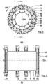
- the carrier element contact surfaces 32, 33, 34 are designed to be angled to an intersecting radial R in a cross section that is perpendicular to the axis of rotation DA ( Fig. 13 ).
- the carrier element contact surfaces 32, 33, 34 approach from a first contact surface end 36 to a second contact surface end 38 at least regardless of a groove 92 of the Rotation axis DA, wherein the second contact surface end 38 is arranged offset in the direction of rotation UR to the first contact surface end 36 ( Fig. 10 ).
- the carrier elements 16, 18, 19 each have an engagement section 82, 83, 84 with which they engage in engagement recesses 79, 80, 81 of the fixing device 50.
- cover elements 64, 65 by which one half or two thirds of the carrier elements 16, 18, 19 are replaced in the third and fourth chopping drum 2 ( Fig. 16 u. 17).
- the fixing device 50 forms a main bearing 87 and a counter bearing 86.
- the support elements 16, 18, 19 have in cross section ( Fig. 10 ) a first leg 44, on which the respective cutting element 20, 24, 27 is arranged, and a second leg 46, which forms the respective engagement section 82, 83, 84.
- the second leg 46 is angled in cross-section to the first leg 44.
- the main bearing 87 rests on a first side 88 of the second leg 46.
- the counter bearing 86 rests on a second side 90 of the second leg 46 ( Fig. 10 ).
- the counter bearing 86 is designed to lead in the direction of rotation UR with respect to the carrier element 16, 18, 19, and the main bearing 87 is designed to trail in the direction of rotation UR.
- the first leg 44 rests from the outside on the cutting element 20, 24, 27 arranged on the carrier element 16, 18, 19 in such a way that the radial R intersects the cutting element 20, 24, 27 between the first leg 44 and the axis of rotation DA.
- the engagement recesses 79, 80, 81 have a first extension U1 in the direction of rotation UR in cross-section at a first radius R1. At a second radius R2, which is smaller than the first radius R1, the engagement recesses 79, 80, 81 have a second extension U2 in the direction of rotation UR, which is greater than the first extension U1 ( Fig. 15 ).
- the carrier elements 16, 18, 19 have a projection 94 which is visible in cross-section and which extends longitudinally, parallel to the cutting edge 22, 26, 29 of the cutting element 20, 24, 27 arranged on the carrier element 16, 18, 19.
- the projection 94 extends into the grooves 92 of the fixing elements 10, 12, 14.
- the groove 92 is arranged offset from the screw 28.
- the cutting elements 20, 24, 27 are each arranged between one of the carrier elements 16, 18, 19 and a counter carrier element 58 ( Fig. 7 ).
- the counter-support element 58 tapers towards the cutting edge 22, 26, 29 of the cutting element 20, 24, 27, against which they rest.
- the counter-support elements 58 have an arcuate guide surface 60 for deflecting cut crops by approximately 180°.
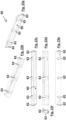
- the counter-support elements 58 have a limiting section 62 protruding at their axial ends relative to the guide surface 60. Between the limiting sections 62, a screw receiving section 63 is arranged for each fixing element 10, 12, 14 ( Fig. 23a ff.).
- the cover elements 64, 65 have a smaller radial extent relative to the axis of rotation DA than the carrier elements 16, 18, 19. Additional cover elements 66 are arranged on the cover elements 64, 65, which have a guide surface 54 facing away from the axis of rotation DA and extend from the respective cover element 64, 65 to the cover element 65 or carrier element 18 advancing in the direction of rotation UR. At least some of the cover elements 64, 65 have a cover leg 67 in cross section, which is similar to the second leg 46 of the carrier elements 16, 18, 19.
- a projection section 69 arranged opposite the second or third engagement section 83, 84 borders the cover leg 67.
- the projection portion 69 protrudes from the cover leg 67 in the direction of rotation UR and has a projection surface 71 facing away from the axis of rotation DA.
- the projection surface 71 adjoins the guide surface 54, 60.
- the chopping drums 2 are manufactured as follows. First, the fixing elements 10, 12, 14 are welded to the outer surface 8 of the hollow shaft 6 ( Fig. 5 ). The fixing elements 10, 12, 14 are then machined ( Fig. 1 to 4 and 6 ). This produces the carrier element contact surfaces 32, 33, 34. In addition, the machining of a torque-absorbing section 40 of the first fixing element 10 produces an input shaft contact surface 42, to which the input shaft 4 is subsequently attached ( Fig. 8 and 11 ). The torque receiving section 40 has a smaller inner diameter than the hollow shaft 6 and is arranged offset in the axial direction AR to the hollow shaft 6. Due to the machining after welding the fixing elements 10, 12, 14, at least apart from the outer fixing elements 10, 52 the fixing elements 12, 14, 52 have an identical raw shape when they are welded ( Fig. 5 ).
- the carrier elements 16, 18, 19 are arranged on the fixing elements 10, 12, 14 after machining.
- the carrier elements 16, 18, 19 are levered with their engagement sections 82, 83, 84 into the engagement recesses 79, 80, 81.
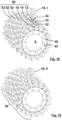
- the carrier elements 16, 18, 19 are moved relative to the fixing device 50 according to five steps I to V and pivoted about a pivot axis SA while resting on the fixing elements 10, 12, 14 ( Fig. 18 - 22 ).
- the projections 94 engage in the grooves 92.
- the pivot axis SA runs parallel to the main direction of extension of the carrier elements 16, 18, 19. After the carrier elements 16, 18, 19 have been levered in, they are fastened, in particular screwed, to the fixing elements 10, 12, 14.
- the cutting elements 20, 24, 27 are then screwed to the carrier elements 16, 18, 19.
- the hollow shaft 6 and the torque absorption section 40 have inner sides extending around the axis of rotation DA, which are shown in the figures in a simplified manner, partly as angular.
- the fixing elements 10, 12, 14, 52 have a complex geometry, which is indicated in particular by lines of lesser thickness. The lines of lesser thickness are not necessarily to be understood as component contours.
Landscapes
- Life Sciences & Earth Sciences (AREA)
- Environmental Sciences (AREA)
- Engineering & Computer Science (AREA)
- Food Science & Technology (AREA)
- Harvester Elements (AREA)
Applications Claiming Priority (1)
| Application Number | Priority Date | Filing Date | Title |
|---|---|---|---|
| DE102023108774.6A DE102023108774A1 (de) | 2023-04-05 | 2023-04-05 | Häckseltrommel für einen Feldhäcksler |
Publications (2)
| Publication Number | Publication Date |
|---|---|
| EP4466979A2 true EP4466979A2 (fr) | 2024-11-27 |
| EP4466979A3 EP4466979A3 (fr) | 2025-02-05 |
Family
ID=92801703
Family Applications (1)
| Application Number | Title | Priority Date | Filing Date |
|---|---|---|---|
| EP24161491.6A Pending EP4466979A3 (fr) | 2023-04-05 | 2024-03-05 | Tambour hacheur pour une récolteuse-hacheuse |
Country Status (2)
| Country | Link |
|---|---|
| EP (1) | EP4466979A3 (fr) |
| DE (1) | DE102023108774A1 (fr) |
Citations (1)
| Publication number | Priority date | Publication date | Assignee | Title |
|---|---|---|---|---|
| DE102012023431A1 (de) | 2012-11-30 | 2014-06-05 | Claas Saulgau Gmbh | Messerträger für eine Häckseltrommel und Häckseltrommel für einen Feldhäcksler |
Family Cites Families (4)
| Publication number | Priority date | Publication date | Assignee | Title |
|---|---|---|---|---|
| GB201306964D0 (en) * | 2013-04-17 | 2013-05-29 | Agco Int Gmbh | Cutting drum for agricultural machine |
| DE102016116193A1 (de) * | 2016-08-31 | 2018-03-01 | Cutmetall Komponenten Gmbh | Rotor einer Zerkleinerungsmaschine mit lösbar befestigten Messerhaltern |
| DE102017106543A1 (de) * | 2017-03-27 | 2018-09-27 | Albach Maschinenbau GmbH | Hackrotor |
| DE102018126694A1 (de) * | 2018-10-25 | 2020-04-30 | Claas Saulgau Gmbh | Häckselmesser einer Häckseltrommel eines Feldhäckslers und Häckseltrommel |
-
2023
- 2023-04-05 DE DE102023108774.6A patent/DE102023108774A1/de active Pending
-
2024
- 2024-03-05 EP EP24161491.6A patent/EP4466979A3/fr active Pending
Patent Citations (1)
| Publication number | Priority date | Publication date | Assignee | Title |
|---|---|---|---|---|
| DE102012023431A1 (de) | 2012-11-30 | 2014-06-05 | Claas Saulgau Gmbh | Messerträger für eine Häckseltrommel und Häckseltrommel für einen Feldhäcksler |
Also Published As
| Publication number | Publication date |
|---|---|
| EP4466979A3 (fr) | 2025-02-05 |
| DE102023108774A1 (de) | 2024-10-10 |
Similar Documents
| Publication | Publication Date | Title |
|---|---|---|
| EP2509745B1 (fr) | Module pour l'équipement ultérieur d'un dispositif de meulage d'électrodes et dispositif de meulage d'électrodes | |
| DE3883976T2 (de) | Segmentierte gleitlagerungseinrichtung für tragbare drehmaschine. | |
| EP0282090A1 (fr) | Fraise à plaquettes | |
| DE102007049057B4 (de) | Einstückig ausgebildeter Messerkopf und Verfahren zum Nachschleifen eines solchen Messerkopfes | |
| DE102015220777B4 (de) | Werkzeugkupplung zwischen zwei Kupplungsteilen sowie Kupplungsteil für eine solche Werkzeugkupplung | |
| EP0008631B1 (fr) | Fraise composée | |
| DE60005891T2 (de) | Verfahren und Vorrichtung zum Entfernen von Nieten | |
| EP1980323B1 (fr) | Système de coupe, en particulier pour une machine pour broyage fin | |
| EP3641983B1 (fr) | Plateau rotatif comprenant un entraînement optimisé en force | |
| EP1967307A1 (fr) | Procédé de fabrication d'un élément de moyeu de rotor pourvu de rainures | |
| EP2509746B1 (fr) | Dispositif pour meuler des électrodes et meule | |
| DE102020003346B3 (de) | Umfangsstabmesserkopf | |
| EP4466979A2 (fr) | Tambour hacheur pour une récolteuse-hacheuse | |
| EP4134488A1 (fr) | Roue de fraise | |
| DE69018997T2 (de) | Kreissägeblattanordnung. | |
| WO2008104316A2 (fr) | Joint tournant entre un arbre et un pignon, et procédé pour établir un tel joint | |
| DE2836630A1 (de) | Kuttermesser | |
| DE69704780T2 (de) | Sägespindel mit genutetem dorn und damit gepaarte hülse mit übereinstimmenden innen- und aussennuten zum montieren von sägeblättern | |
| EP2311568B1 (fr) | Ensemble de coupe doté d'un compteur de bague d'écartement de sécurité | |
| DE102023108775A1 (de) | Häckseltrommel für einen Feldhäcksler | |
| EP3799709B1 (fr) | Pièce moulée pour un composant, composant pourvu de pièce moulée et machine de travail agricole pourvue du composant | |
| EP1654085B1 (fr) | Outil a fraiser | |
| CH648495A5 (de) | Pelletizer. | |
| EP2186591A1 (fr) | Tête de coupe et son procédé de fabrication | |
| EP1767318B1 (fr) | Outil de coupe à enlèvement de copeaux |
Legal Events
| Date | Code | Title | Description |
|---|---|---|---|
| PUAI | Public reference made under article 153(3) epc to a published international application that has entered the european phase |
Free format text: ORIGINAL CODE: 0009012 |
|
| STAA | Information on the status of an ep patent application or granted ep patent |
Free format text: STATUS: THE APPLICATION HAS BEEN PUBLISHED |
|
| AK | Designated contracting states |
Kind code of ref document: A2 Designated state(s): AL AT BE BG CH CY CZ DE DK EE ES FI FR GB GR HR HU IE IS IT LI LT LU LV MC ME MK MT NL NO PL PT RO RS SE SI SK SM TR |
|
| PUAL | Search report despatched |
Free format text: ORIGINAL CODE: 0009013 |
|
| P01 | Opt-out of the competence of the unified patent court (upc) registered |
Free format text: CASE NUMBER: APP_63770/2024 Effective date: 20241202 |
|
| AK | Designated contracting states |
Kind code of ref document: A3 Designated state(s): AL AT BE BG CH CY CZ DE DK EE ES FI FR GB GR HR HU IE IS IT LI LT LU LV MC ME MK MT NL NO PL PT RO RS SE SI SK SM TR |
|
| RIC1 | Information provided on ipc code assigned before grant |
Ipc: B02C 18/18 20060101ALI20250102BHEP Ipc: B02C 18/14 20060101ALI20250102BHEP Ipc: A01F 29/09 20100101ALI20250102BHEP Ipc: A01F 29/06 20060101AFI20250102BHEP |
|
| STAA | Information on the status of an ep patent application or granted ep patent |
Free format text: STATUS: REQUEST FOR EXAMINATION WAS MADE |
|
| 17P | Request for examination filed |
Effective date: 20250213 |