EP4467401A1 - Guide de ceinture de sécurité - Google Patents
Guide de ceinture de sécurité Download PDFInfo
- Publication number
- EP4467401A1 EP4467401A1 EP24175043.9A EP24175043A EP4467401A1 EP 4467401 A1 EP4467401 A1 EP 4467401A1 EP 24175043 A EP24175043 A EP 24175043A EP 4467401 A1 EP4467401 A1 EP 4467401A1
- Authority
- EP
- European Patent Office
- Prior art keywords
- seat belt
- belt guide
- guide
- barb
- frame
- Prior art date
- Legal status (The legal status is an assumption and is not a legal conclusion. Google has not performed a legal analysis and makes no representation as to the accuracy of the status listed.)
- Pending
Links
Images



Classifications
-
- B—PERFORMING OPERATIONS; TRANSPORTING
- B60—VEHICLES IN GENERAL
- B60R—VEHICLES, VEHICLE FITTINGS, OR VEHICLE PARTS, NOT OTHERWISE PROVIDED FOR
- B60R22/00—Safety belts or body harnesses in vehicles
- B60R22/18—Anchoring devices
-
- B—PERFORMING OPERATIONS; TRANSPORTING
- B60—VEHICLES IN GENERAL
- B60R—VEHICLES, VEHICLE FITTINGS, OR VEHICLE PARTS, NOT OTHERWISE PROVIDED FOR
- B60R22/00—Safety belts or body harnesses in vehicles
- B60R22/18—Anchoring devices
- B60R2022/1818—Belt guides
-
- B—PERFORMING OPERATIONS; TRANSPORTING
- B60—VEHICLES IN GENERAL
- B60R—VEHICLES, VEHICLE FITTINGS, OR VEHICLE PARTS, NOT OTHERWISE PROVIDED FOR
- B60R22/00—Safety belts or body harnesses in vehicles
- B60R22/18—Anchoring devices
- B60R2022/1818—Belt guides
- B60R2022/1831—Belt guides comprising a slotted plate sliding in its plane, e.g. inside circular guides
Definitions
- the present invention generally relates to a seat belt guide.
- the present invention generally relates to the field of fasteners, and in particular, to the fields of fastening clips for attaching one or more components, such as, for example, seat belt guide loops for a vehicle.
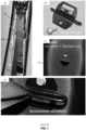
- Brackets are known in the art and common brackets are used to attach a supplier's seat belt module to, for example, a vehicles B-pillar (see FIG. 1 ).
- the prior art brackets require a relatively complex assembly including keyholes at the bracket, screws and/or a welded nut provided on the B-Pillar ("frame" 104).
- a seat belt guide comprising: a guide portion for slidably retaining a seatbelt; at least one connecting portion for attaching the seat belt guide to a frame; wherein the at least one connecting portion comprises at least one barb and at least one stop; wherein the barb is arranged in opposition to the at least one stop; and wherein the barb comprises a biting surface, and the barb is resiliently biased in a direction different to a direction that the biting surface is arranged to bite in.
- the barb and stop are sufficient in themselves to adequately attach the seat belt guide to the frame. No further fixings or work is required (such as welding).
- the seat belt guide may be attached to the frame by hand with no additional tooling required.
- the guide portion comprises an seat-belt receiving aperture.
- the seat belt guide may be pre-attached to a seat belt, with the seat belt passing through the aperture.
- the seat-belt receiving aperture comprises a continuous wall about a perimeter of the seat-belt receiving aperture.
- the seat belt may be passed through the aperture upon construction, such that the seat belt cannot be removed or pass by the continuous wall without disassembly or destructions of the seat belt (e.g. By cutting the belt).
- the seat belt guide comprises at least two connecting portions. Multiple connecting portions may be used to ensure an adequate attachment of the seat belt guide or to accommodate alternative designs of seat belt guide, such as one where a single guide portion is straddled by at least two connecting portions. Likewise, multiple seat belt guides may be attached to one or more connecting portions which may be useful in situations where multiple seat belts are located in close proximity, such as the middle seats of a bench of seats in a vehicle.
- the connecting portion is arranged, in use, to straddle a wall of a frame, with the at least one barb on a first side of the wall and the at least one stop on a second face of the wall, wherein the second face is opposite to the first face.
- the wall of the frame is pinched between the biting surface of the at least one barb and the stop, ensuring that the frame is grasped by the connecting portion.
- the at least one barb and the at least one stop are spaced apart by a distance which is less than a thickness of a frame wall. Reducing the space between the biting surface of the barb and the at least one stop ensures that the bard bites the frame sufficiently to ensure a stead-fast grip, or even that the barb bites into the frame material.
- the at least one stop is resiliently biased.
- the stop may be sprung such that vibrations in the frame or movement of the seat guide (such as by nefarious or mischievous persons urging the seat guide away from the frame) are resisted and a secure fit of the seat belt guide to the frame is maintained.
- the at least one stop is resiliently biased, in use, towards the frame.
- the pinching of the frame by the barb and the stop is enhanced as both the barb are stop are urged towards the frame in opposing directions, thereby forming a pincer grip.
- the barb comprises a ramped surface arranged to engage with the frame.
- the biting surface may be continuous with, or formed by, the ramped surface.
- the ramped surface provides a tolerance to the connecting portion to accommodate a variety of thicknesses of frame wall, either by design (some frames may be formed of thicker materials than others) or to accommodate relaxed design tolerances.
- the ramp ensures that the biting surface of the barb at least partially engages with the frame at a location along the ramped surface.
- the at least one connecting portion is formed in a single piece. Manufacture of the connecting portion is simplified and the risk of the connecting portion disassembling is avoided. A user of the connecting portion also avoids the need to assemble the connecting portion thereby saving time.
- the seat belt guide is formed in a single piece. Manufacture of the seat belt guide is simplified and the risk of the seat belt guide disassembling is avoided. A user of the seat belt guide also avoids the need to assemble the seat belt guide thereby saving time.
- the seat belt guide is formed of one or more metals.
- the seat belt is a safety critical element in a vehicle an appropriate material must be selected to ensure adequate function is maintained, should the seat belt ever be required.
- the structure of the seat belt guide consists of one or more metals.
- the structure here refers to those elements which form the seat belt guide, that is at least the guide portion and connecting portion.
- the entire seat belt guide is formed from a single metal.
- the seat belt guide is partially or wholly formed by stamping.
- the seat belt guide may be formed in a single manufacturing step in order to quickly produce a high volume easily.
- the at least one stop is arranged on the at least one barb. Arranging the stop so that it is connected to the barb ensures that the stop is located optimally relative to the barb on use of the seat belt guide.
- the connecting portion grasps at least one leg of the guide portion preventing rotation and/or translational movement of the guide portion relative to the connecting portion. This ensures the guide portion is held in a single and predictable position when in place on the frame.
- the terms 'connected', 'attached', 'coupled' and 'mounted' are intended to include direct connections between two members without any other members interposed therebetween, as well as, indirect connections between members in which one or more other members are interposed therebetween.
- the terminology includes the words specifically mentioned above, derivatives thereof, and words of similar import.
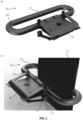
- the illustrated example embodiment in FIG. 2 relates to a seat belt guide 202 used for the assembly of vehicle components.
- the seat belt guide 202 of the present invention includes a connecting portion 206 operably mountable with respective apertures in, for example, a B-pillar of a vehicle ("frame"), in order to provide a seat belt guide for an assembled and installed seat belt system (as shown in FIG. 2 ).
- the drawings illustrate a new screwless design for the fastener ("connecting portion” 206) and guide loop ("guide portion” 210, for the seat belt).
- the connecting portion 206 is provided by a stamped sheet metal that is folded so as to moveably retain a guide portion 210 for a seat belt 212.
- a body portion extends along a central axis (in line with or parallel to the direction of insertion into the aperture during assembly) and respective resilient leg members extend laterally outward from a distal portion of the fastener body and in a direction toward the guide loop, so as to form a V-shaped spring clip arrangement.
- Each one of the resilient leg members has a U-shaped retainer member arranged on its distal end.
- the U-shaped retainer member is arranged with its open end facing laterally outward, such that the U-shaped retainer members can retainingly engage with the side wall of the pillar aperture in order to securely but (easily) removably attach the fastener to the pillar wall.
- the resilient leg members form barbs 218 having a biting surface 204 which grasp the frame when inserted. Also attached to the resilient leg members (and therefore the barbs 218) are respective stops 216 which abut an opposing face of a frame wall, opposite the site bitten by the biting surface 204 of the barb 218.
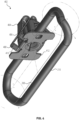
- FIG. 3 shows a detailed example (incl. dimensions) of the guide portion 210 and the sheet metal blank ready to be formed into the fastener clip.
- the guide portion 210 has an aperture through which a seat belt may be passed.
- the aperture is bounded by a continuous wall 208 about a perimeter of the aperture. In this way the seat belt is captured within the aperture and may not escape or detach from the guide portion 210 without intentional disassembly (destructive or otherwise).
- FIG. 4 shows an alternative seat belt guide 402 also comprising a guide portion 210 formed of a loop and sharing like features with the guide portion 210 shown in FIG. 2 and FIG. 3 .
- the connecting portion 404 is formed of a plate.
- the plate may be formed of metal.
- the connecting portion 404 may be formed in a stamping process.
- the connecting portion 404 has a stop 412 arranged to abut a frame once installed and prevent further movement of the seat belt guide 402 into the frame apertures.
- Opposing the stop 412 are one or more barbs 406.
- Each barb 406 has a biting surface 408 arranged to bite the frame when the seat belt guide 402 is inserted into a frame aperture and pinch the frame between the biting surface 408 and the stop 412.
- the biting surface 408 is arranged upon a ramped surface 410.
- the ramped surface 410 ensures that the biting surface of the barb at least partially engages with the frame at a location along the ramped surface as described elsewhere in this disclosure.
- FIG. 5 shows an alternative seat belt guide 504 attached to a frame 512 (in partial transparency for illustrative purposes) and retaining a seat belt 502.
- the seat belt guide 504 has a guide portion 514 formed of a strip of material (typically metal) with a connecting portion 510 located at each end of the 514.
- the guide portion 514 when in position upon the frame 512 retains the seat belt 502 between the guide portion 514 and the frame 512.
- the seat belt 502 is not captured by the guide portion 514 unlike the seat belt guides of FIG. 2 and FIG. 4 .
- the present seat belt guide 504 may be attached separately to the seat belt 502.
- Each connecting portion 510 comprises a barb 506 having a biting surface 508 which bites the frame 512 when in position.
- a stop 516 is provided to abut the frame 512 on an opposing surface to that bitten by the barb 506 and thereby hold the seat belt guide 504 in place by pinching the frame 512 between the barb 506 and the stop 516.
- FIG. 6 shows an alternative seat belt guide similar to that shown in FIG. 4 and sharing similar attributes (like numbering provided as appropriate for shared features). Features are also shared with the guide portion 210 shown in FIG. 2 and FIG. 3 .
- the seat belt guide 604 is formed having at least one leg 606 attached.
- the seat belt guide 604 may be formed of a single piece with the leg 606 formed by bending or otherwise deforming a part of the seat belt guide 604 to form the leg 606.
- the one or more legs 606 may be added separately to a preformed seat belt guide 604.
- the seat belt guide 604 is shown as an open ring-like structure, but may be formed of an enclosed ring, similar to that shown in FIG. 3 , and with one or more legs 606 added later.
- the connecting portion 404 is provided with internal space to receive the one or more legs 606 of the seat belt guide 604.
- the connecting portion 404 is formed over the one or more legs 606 thereby grasping and holding the legs in a fixed position relative to the connecting portion 404.
- the connecting portion 404 is provided with multiple arresting surfaces which contact the one or more legs 606 in multiple dimensions thereby arresting movement of the one or more legs 606 relative to the connecting portion 404. In this way the connecting portion 404 arrests movement of the seat belt guide 604 relative to the connecting portion 404 preventing rotation and translational movement of the seat belt guide 604 relative to the connecting portion 404.
- the barbs described herein may be biased in a direction away from the direction the biting surface is directed. This is to ensure, that when passed through the frame aperture the barbs move away from the aperture to place the biting surface above the frame material rather than the empty space of the aperture, thereby assuring a successful bite by the barb.
- the stops described herein may be biased towards the barbs by, for example, using a sprung or otherwise resilient material. This ensures that the barb and stop are together urged towards the frame material further ensuring a successful pinching of the frame material and allowing the seat belt guide to successfully attach.
- the new fastener for the seat belt systems disclosed herein are robust and allow a smooth movement (coated metal surface) during installation. It is easy to use when assembled or disassembled, thus, improving productivity through faster assembly speed (Poka-yoke & anti-rotation feature through a rectangular hole / aperture). No welding or installation tools are required during assembly / mounting.
- the fastener is made up of a single component, rather than multiple components (screws, nuts etc.) that are need for currently known brackets.
- the simple construction allows for a lighter solution that what is currently available.
- Any suitable, resilient and formable material may be used for the seat belt guide and fastener portion, as well as, the guide loop. Metals are particularly suitable due to the intended safety purpose of the device. It is advantageous to form the seat belt guide from a single metal for simplicity of manufacture.
Landscapes
- Engineering & Computer Science (AREA)
- Mechanical Engineering (AREA)
- Automotive Seat Belt Assembly (AREA)
Priority Applications (2)
| Application Number | Priority Date | Filing Date | Title |
|---|---|---|---|
| US18/668,895 US20240391414A1 (en) | 2023-05-22 | 2024-05-20 | Seat Belt Guide |
| CN202410630319.6A CN118991667A (zh) | 2023-05-22 | 2024-05-21 | 座椅安全带引导件 |
Applications Claiming Priority (1)
| Application Number | Priority Date | Filing Date | Title |
|---|---|---|---|
| EP23382475 | 2023-05-22 |
Publications (1)
| Publication Number | Publication Date |
|---|---|
| EP4467401A1 true EP4467401A1 (fr) | 2024-11-27 |
Family
ID=86497482
Family Applications (1)
| Application Number | Title | Priority Date | Filing Date |
|---|---|---|---|
| EP24175043.9A Pending EP4467401A1 (fr) | 2023-05-22 | 2024-05-09 | Guide de ceinture de sécurité |
Country Status (3)
| Country | Link |
|---|---|
| US (1) | US20240391414A1 (fr) |
| EP (1) | EP4467401A1 (fr) |
| CN (1) | CN118991667A (fr) |
Citations (7)
| Publication number | Priority date | Publication date | Assignee | Title |
|---|---|---|---|---|
| DE102006061617A1 (de) * | 2006-12-27 | 2008-07-03 | Volkswagen Ag | Befestigungsanordnung, insbesondere zum Halten eines Umlenkbeschlags für einen Gurtbandabschnitt eines Sicherheitsgurtes in einem Fahrzeug, sowie Verfahren zum Befestigen eines Umlenkbeschlags an einer Trägerwand |
| JP2011085174A (ja) * | 2009-10-14 | 2011-04-28 | Honda Motor Co Ltd | 部品の取付構造 |
| DE102013018525B4 (de) * | 2013-11-04 | 2015-08-13 | Audi Ag | Gurtführungseinrichtung eines Sicherheitsgurtes für einen Fahrzeugsitz eines Fahrzeugs sowie ein zugehöriger Gurtführungsbügel |
| ES2765982A1 (es) * | 2018-12-11 | 2020-06-11 | Illinois Tool Works | Dispositivo de sujeción para vehículos |
| CN211731316U (zh) * | 2019-06-10 | 2020-10-23 | 爱驰汽车有限公司 | 安全限位装置的安装机构及其应用的车辆 |
| DE102021111989A1 (de) * | 2020-05-19 | 2021-11-25 | Illinois Tool Works Inc. | Gurtführungsvorrichtung für einen Passagierrückhaltegurt eines Kraftfahrzeugs |
| CN114074635A (zh) * | 2020-08-21 | 2022-02-22 | 伊利诺斯工具制品有限公司 | 安全带导向装置 |
Family Cites Families (13)
| Publication number | Priority date | Publication date | Assignee | Title |
|---|---|---|---|---|
| JPH04283149A (ja) * | 1991-03-08 | 1992-10-08 | Takata Kk | ショルダーアジャスタ |
| US6234529B1 (en) * | 1999-12-22 | 2001-05-22 | Honda Giken Kogyo Kabukshiki Kaisha | Seat belt routing via roof mount |
| US20040080194A1 (en) * | 2002-10-28 | 2004-04-29 | Johnson Controls Technology Company | Mechanical attachment of anchorage |
| DE102004041665B4 (de) * | 2004-08-27 | 2015-01-15 | Trw Automotive Gmbh | Gurtführung sowie Gurtaufroller mit einer solchen Gurtführung |
| GB0511317D0 (en) * | 2005-06-03 | 2005-07-13 | Macliver Kevin S | Restraining |
| US7296854B2 (en) * | 2005-11-17 | 2007-11-20 | Illinois Tool Works Inc | Safety seat restraint system |
| US7390022B2 (en) * | 2006-08-04 | 2008-06-24 | Tk Holdings Inc. | Integrated seat belt shoulder anchor |
| FR2926046B1 (fr) * | 2008-01-08 | 2009-12-25 | Peugeot Citroen Automobiles Sa | Dispositif destine a l'attache d'une extremite d'une ceinture de securite et a l'arrimage d'un equipement de retenue de charge dans un habitacle de vehicule automobile. |
| EP2496848B1 (fr) * | 2009-11-04 | 2016-03-09 | Illinois Tool Works Inc. | Écrou rapide démontable et réutilisable |
| DE102010023662A1 (de) * | 2010-06-12 | 2011-01-27 | Daimler Ag | Befestigungsanordnung für einen Gurtführungsbügel eines Sicherheitsgurtes |
| DE102010051483B4 (de) * | 2010-11-15 | 2022-06-23 | Volkswagen Ag | Befestigungsanordnung für einen Umlenkbeschlag eines Sicherheitsgurts |
| DE102011119676B4 (de) * | 2011-11-29 | 2023-08-03 | Volkswagen Aktiengesellschaft | Gurtumlenkbeschlag für einen Sicherheitsgurt und Befestigungsanordnung |
| CN118765240A (zh) * | 2022-05-20 | 2024-10-11 | 提爱思科技股份有限公司 | 车辆座椅 |
-
2024
- 2024-05-09 EP EP24175043.9A patent/EP4467401A1/fr active Pending
- 2024-05-20 US US18/668,895 patent/US20240391414A1/en active Pending
- 2024-05-21 CN CN202410630319.6A patent/CN118991667A/zh active Pending
Patent Citations (7)
| Publication number | Priority date | Publication date | Assignee | Title |
|---|---|---|---|---|
| DE102006061617A1 (de) * | 2006-12-27 | 2008-07-03 | Volkswagen Ag | Befestigungsanordnung, insbesondere zum Halten eines Umlenkbeschlags für einen Gurtbandabschnitt eines Sicherheitsgurtes in einem Fahrzeug, sowie Verfahren zum Befestigen eines Umlenkbeschlags an einer Trägerwand |
| JP2011085174A (ja) * | 2009-10-14 | 2011-04-28 | Honda Motor Co Ltd | 部品の取付構造 |
| DE102013018525B4 (de) * | 2013-11-04 | 2015-08-13 | Audi Ag | Gurtführungseinrichtung eines Sicherheitsgurtes für einen Fahrzeugsitz eines Fahrzeugs sowie ein zugehöriger Gurtführungsbügel |
| ES2765982A1 (es) * | 2018-12-11 | 2020-06-11 | Illinois Tool Works | Dispositivo de sujeción para vehículos |
| CN211731316U (zh) * | 2019-06-10 | 2020-10-23 | 爱驰汽车有限公司 | 安全限位装置的安装机构及其应用的车辆 |
| DE102021111989A1 (de) * | 2020-05-19 | 2021-11-25 | Illinois Tool Works Inc. | Gurtführungsvorrichtung für einen Passagierrückhaltegurt eines Kraftfahrzeugs |
| CN114074635A (zh) * | 2020-08-21 | 2022-02-22 | 伊利诺斯工具制品有限公司 | 安全带导向装置 |
Also Published As
| Publication number | Publication date |
|---|---|
| US20240391414A1 (en) | 2024-11-28 |
| CN118991667A (zh) | 2024-11-22 |
Similar Documents
| Publication | Publication Date | Title |
|---|---|---|
| CN205744763U (zh) | 紧固夹系统和紧固组件 | |
| US9649993B1 (en) | One step assembly fastener clip | |
| US8458979B2 (en) | Interior panel attachment system | |
| KR101496369B1 (ko) | 좌석 벨트 앵커 조립체 | |
| EP1510702B1 (fr) | Attache-clip resiliente | |
| US8267478B2 (en) | Vehicle seat and assembly method | |
| US6758645B2 (en) | Locking cage fastener | |
| CA2351970C (fr) | Ancrage et systeme d'attache de siege d'auto | |
| US9688123B2 (en) | Load transmission member | |
| EP1439313A2 (fr) | Système de fixations en deux parties, en particulier dispositif de retenue de pièce d'habillage intérieur | |
| US6176660B1 (en) | Releasable fastener with lateral stabilizing brace members and latch legs carrying fastener insertion guide | |
| US6540251B1 (en) | Side airbag retention system and fastener | |
| JP2019006204A (ja) | アンカ装置 | |
| US20250084879A1 (en) | Fastening Clip | |
| US20240391414A1 (en) | Seat Belt Guide | |
| CN113696831B (zh) | 弹性夹 | |
| KR20170011977A (ko) | 테일 파이프 장착 시스템 | |
| EP2613062B1 (fr) | Fixation d'isolation et de protection | |
| CA2415819A1 (fr) | Pince de retenue | |
| US20130189048A1 (en) | Fastener | |
| EP1696141A1 (fr) | Dispositif de retenue attaché | |
| CN104602570A (zh) | 扶手安装构造 | |
| US20250012305A1 (en) | Fastening Clip Assembly | |
| US11167720B2 (en) | Low-profile seatbelt buckle assembly | |
| EP2198171A1 (fr) | Agrafe de garnissage |
Legal Events
| Date | Code | Title | Description |
|---|---|---|---|
| PUAI | Public reference made under article 153(3) epc to a published international application that has entered the european phase |
Free format text: ORIGINAL CODE: 0009012 |
|
| STAA | Information on the status of an ep patent application or granted ep patent |
Free format text: STATUS: THE APPLICATION HAS BEEN PUBLISHED |
|
| AK | Designated contracting states |
Kind code of ref document: A1 Designated state(s): AL AT BE BG CH CY CZ DE DK EE ES FI FR GB GR HR HU IE IS IT LI LT LU LV MC ME MK MT NL NO PL PT RO RS SE SI SK SM TR |
|
| STAA | Information on the status of an ep patent application or granted ep patent |
Free format text: STATUS: REQUEST FOR EXAMINATION WAS MADE |
|
| STAA | Information on the status of an ep patent application or granted ep patent |
Free format text: STATUS: EXAMINATION IS IN PROGRESS |
|
| 17P | Request for examination filed |
Effective date: 20250520 |
|
| 17Q | First examination report despatched |
Effective date: 20250612 |