EP4467824A1 - Écrou à ressort antidesserrage - Google Patents
Écrou à ressort antidesserrage Download PDFInfo
- Publication number
- EP4467824A1 EP4467824A1 EP22920744.4A EP22920744A EP4467824A1 EP 4467824 A1 EP4467824 A1 EP 4467824A1 EP 22920744 A EP22920744 A EP 22920744A EP 4467824 A1 EP4467824 A1 EP 4467824A1
- Authority
- EP
- European Patent Office
- Prior art keywords
- bolt
- nut
- spring
- female thread
- loosening
- Prior art date
- Legal status (The legal status is an assumption and is not a legal conclusion. Google has not performed a legal analysis and makes no representation as to the accuracy of the status listed.)
- Pending
Links
Images






Classifications
-
- F—MECHANICAL ENGINEERING; LIGHTING; HEATING; WEAPONS; BLASTING
- F16—ENGINEERING ELEMENTS AND UNITS; GENERAL MEASURES FOR PRODUCING AND MAINTAINING EFFECTIVE FUNCTIONING OF MACHINES OR INSTALLATIONS; THERMAL INSULATION IN GENERAL
- F16B—DEVICES FOR FASTENING OR SECURING CONSTRUCTIONAL ELEMENTS OR MACHINE PARTS TOGETHER, e.g. NAILS, BOLTS, CIRCLIPS, CLAMPS, CLIPS OR WEDGES; JOINTS OR JOINTING
- F16B39/00—Locking of screws, bolts or nuts
- F16B39/02—Locking of screws, bolts or nuts in which the locking takes place after screwing down
- F16B39/12—Locking of screws, bolts or nuts in which the locking takes place after screwing down by means of locknuts
- F16B39/14—Locking of screws, bolts or nuts in which the locking takes place after screwing down by means of locknuts made of thin sheet material or formed as spring-washers
-
- F—MECHANICAL ENGINEERING; LIGHTING; HEATING; WEAPONS; BLASTING
- F16—ENGINEERING ELEMENTS AND UNITS; GENERAL MEASURES FOR PRODUCING AND MAINTAINING EFFECTIVE FUNCTIONING OF MACHINES OR INSTALLATIONS; THERMAL INSULATION IN GENERAL
- F16B—DEVICES FOR FASTENING OR SECURING CONSTRUCTIONAL ELEMENTS OR MACHINE PARTS TOGETHER, e.g. NAILS, BOLTS, CIRCLIPS, CLAMPS, CLIPS OR WEDGES; JOINTS OR JOINTING
- F16B39/00—Locking of screws, bolts or nuts
- F16B39/02—Locking of screws, bolts or nuts in which the locking takes place after screwing down
- F16B39/20—Locking of screws, bolts or nuts in which the locking takes place after screwing down by means of steel wire or the like
Definitions
- the present invention relates to an anti-loosening spring nut. More specifically, the present invention relates to an anti-loosening spring nut which is fastened using standard tools to a bottom portion of a nut fastened to a bolt, to prevent loosening of the nut.
- a bolt and nut are fastened to couple two objects in various fields, such as assembly of automotive components, assembly of electronic components, assembly of furniture, and assembly of structures at construction sites.
- fastened bolts and nuts have a problem in that they come to be loosened due to external impact or vibration from vehicle operation, resulting in accidents.
- such anti-loosening female threaded spring has the form of a spring that is wound a certain number of times to have an outer diameter corresponding to that of the male threads of the bolt, thus has the limitation of not being able to be fastened to a bolt using standard tools in the field.
- a purpose of the present invention devised to solve the problems described in the above, is to provide an anti-loosening spring nut which can be fastened quickly to a bolt using standard tools while maintaining the anti-loosening function of a conventional female-threaded spring.
- Another purpose of the present invention is to provide an anti-loosening spring nut which spins without traction once coupled to a bottom portion of a nut fastened to a bolt using a standard tool, thereby improving tool adaptability.
- the purpose(s) of the present invention may be achieved by means of an anti-loosening spring nut, which is coupled to a bottom portion of a nut 20 fastened to a bolt 10, to prevent loosening of the nut 20.
- the anti-loosening spring nut according to the present invention comprises: female thread spring 120 which is wound a certain number of times along male threads of a bolt 10, and at whose lower portion and upper portion are projectingly formed, respectively, a lower catching loop end 123 and an upper catching loop end 121, at directions different from each other and outward in a radial direction, and; an external casing 110 which has a shape of an enclosure accommodating the female thread spring 120, on a bottom plate 111 of which is penetratingly formed a bolt insertion hole 111a into which the bolt 10 is inserted, and along whose side face 113 are provided a plurality of pushing projections 114 which are depressedly formed inward at constant intervals, and is characterized: in that the female thread spring 120 is accommodated
- the external casing 110 comprises: a side face 113 whose cross-section is formed in a polygonal shape to allow for use of a standard tool, and; a plurality of covering wings 115 which are folded inward from an upper edge of the side face 113 to cover the female thread spring 120, and is characterized in that: the plurality of pushing projections 114 is formed depressedly inwards from each of the edge faces of the polygon, to a depth at which they cause the female thread spring 120 to become aligned at a center of the external casing 110, so that the female thread spring 120 may be screw-coupled to the male threads of the bolt 10.
- the upper catching loop end 121 comes into contact with the pushing projections 114 with the external casing 110 secured in place, reducing the outer diameter of the female thread spring 120 and preventing loosening of the bolt 10 or the nut 20.
- the anti-loosening spring nut of the present invention comprises: a female thread spring 120 which is wound a certain number of times along male threads of the bolt 10, and at whose lower portion and upper portion are projectingly formed, respectively, a lower catching loop end 123 and an upper catching loop end 121, at directions different from each other and outward in a radial direction; a ratchet external casing 110a which has a shape of an enclosure accommodating the female thread spring 120, on a bottom plate 111 of which is penetratingly formed a hub insertion hole 111a-1 having an external diameter greater than the external diameter of the bolt 10, and along whose side face 113 are provided a plurality of short pushing projections 114-1 which are depressedly formed inward at constant intervals, and; an internal casing 130 which is accommodated
- the internal casing 130 comprises: an internal casing wall 131 on which the plurality of receiving projections 132 is formed; a bearing floor plate 133 which is formed to project inward by a certain distance from the wall of the internal casing 130 in a direction parallel to the bottom edge of the wall to overlap the bottom plate 111, and; a projecting hub 133a which is formed to project inward by a certain distance from the bearing floor plate 133 and project downward and outward through the hub insertion hole 111a-1, and on which is formed an internal bolt insertion hole 133c into which the bolt 10 is inserted, and is characterized in that: the receiving projection 132 is formed depressedly inwards to a depth at which it causes the female thread spring 120 to become aligned at a center of the internal casing 130, so that the female thread spring 120 becomes screw-coupled to the male threads of the bolt 10.
- the short pushing projection 114-1 passes over the receiving projection 132, causing the external casing 110 to spin without traction about the projecting hub 133a and around the internal casing 130.
- a female thread spring used to prevent loosening of a bolt is accommodated within an external casing which may be manipulated using a standard tool, and a pushing projection formed on an inner wall face thereof presses against an upper catching loop end and a lower catching loop end of the female thread spring to cause the female thread spring to become fastened to or loosened from a bolt.
- the present invention has the advantage of being able to be fastened quickly to a bolt using a standard tool while maintaining the anti-loosening function of a female thread spring.
- the anti-loosening spring nut of the present invention provides a ratchet function by adding an internal casing and providing a receiving projection which is pushed against by a pushing projection, causing the external casing to spin without traction once the anti-loosening spring nut has been fastened beneath the nut.
- the present invention has enhanced adaptability to standard tools, providing the benefit of faster installation.
- FIG. 1 is a skew drawing illustrating the anti-loosening spring nut 100 according to a preferred embodiment of the present invention, fastened to a bolt 20 together with a nut 10
- FIG. 2 is a skew drawing illustrating the elements of the anti-loosening spring nut
- FIG. 3 is an exploded skew drawing illustrating separately the elements of the anti-loosening spring nut 100
- FIG. 4 is a side section illustrating the cross section of the anti-loosening spring nut 100
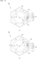
- FIG. 5 is an exemplary plan drawing illustrating the acting mechanism of the anti-loosening spring nut 100.
- the anti-loosening spring nut 100 of the present invention is fastened to a bolt 10, in contact with the bottom face of a nut 20 fastened to said bolt 10, thereby preventing rotation of the bolt 10, keeping the bolt 10 and nut 20 from becoming loose, and stably keeping the bolt 10 and nut 20 fastened for an extended period of time.
- the anti-loosening spring nut 100 as illustrated in FIG. 2 , comprises an enclosure-shaped external casing 110, and a female thread spring 120 which is accommodated within the external casing 110.
- the periphery of the external casing 110 which accommodates the female thread spring 120, is rotated in the forward and reverse directions by a standard tool, causing the female thread spring 120 to become fastened to or loosened from the bolt 10.
- a worker needs only manipulate the external casing 110 in the forward and reverse directions using standard tools in the same manner as an ordinary nut.
- the tool adaptability of the anti-loosening spring nut 100 is enhanced, providing the benefit of being able to quickly fasten the anti-loosening spring nut 100 to a bolt 10.
- the female thread spring 120 is screw-coupled to the male threads 13 of the bolt 10 when the external casing 110 is rotated, preventing loosening of the bolt 10.
- the female thread spring 120 is formed by winding a number of times to have an inner radius R which corresponds to the female threads of the bolt 10.
- the female thread spring 120 according to a preferred embodiment of the present invention is provided in a form wound 2 times, this is but a single embodiment, and the female thread spring 120 may be provided in a form wound 1 time only or wound 3 times or more as needed.
- an upper catching loop end 121 and a lower catching loop end 123 which project outward from a radial direction.
- the upper catching loop end 121 and the lower catching loop end 123 are formed by bending in directions opposite each other.
- the external casing 110 as illustrated in FIG. 3 , comprises a bottom plate 111, a side face 113 formed perpendicularly to the periphery of the bottom plate 111, and a plurality of covering wings 115 which are foldable coupled to the top edge of the side face 113.
- the cross section of the external casing 110 is formed in a polygonal shape to allow for rotation using a standard tool, for example a spanner, wrench, electric screwdriver, nut runner, and the like.
- the external casing 110 may be provided in a triangular shape as illustrated in (a) of FIG. 6 , in a square shape as illustrated in (b) of FIG. 6 , in a hexagonal shape as illustrated in (c) of FIG. 6 , or in various other shapes having corners which can be gripped by a standard tool, as illustrated in (d) through (e) of FIG. 6 .
- the bottom plate 111 is formed to have a polygonal shape, with a bolt insertion hole 111a for insertion of a bolt 10 formed on the plate face with an external diameter corresponding to that of the bolt 10.
- the covering wings 115 are provided at the upper edge of the side faces 113 in a number corresponding to the number of edges of the polygon, and are folded about a crease 115a to cover the top of the external casing 110 accommodating the female thread spring 120 and secure the position of the female thread spring 120 in place.
- the covering wings 115 are provided to come into close contact with the top of the female thread spring 120, so that the position of the female thread spring 120 within the external casing 110 is secured in place and unable to move up or down.
- a cutout 115b is formed at the corner so that the covering wings 115 do not interfere with each other when folded in about the crease 115a.
- Each covering wing 115 is provided to have an area such that allows for a space corresponding to the outer diameter of the bolt insertion hole 111a to be formed when a plurality of the covering wings 115 is folded inward, as illustrated in FIG. 1 .
- the side faces 113 are provided to have a polygonal shape, and a height to allow for the spring female screw 120 to be accommodated within the external casing 110.
- a pushing projection 114 is depressedly formed inward.
- the depression depth h of the pushing projection 114 is a depth that allows for a plurality of the pushing projections 114 to press against the periphery of the spring female screw 120, causing the spring female screw 120 to become aligned at the center of the external casing 110.
- the depression depth h of the pushing projection 114 is determined with consideration for the outer diameter of the female thread spring 120 and the width of the external casing 110.
- the pushing projection 114 pushes against the upper catching loop end 121 or the lower catching loop end 123 of the female thread spring 120, causing the female thread spring 120 to turn together with the external casing and thereby become fastened to or loosened from the bolt 10.
- the pushing projection 114 as illustrated in (a) of FIG. 4 , is formed by bending to have a triangular cross section.
- One of a plurality of pushing projections 114 is positioned between the upper catching loop end 121 and the lower catching loop end 123.
- FIG. 4 is an exemplary drawing illustrating a process by which the anti-loosening spring nut 100 is fastened to a bolt 10 in a case where the bolt 10 is right-threaded, and the female thread spring 120 is screw-coupled to the male threads of the bolt 10.
- a nut 20 is fastened to the bottom of the bolt 10.
- a worker fastens the anti-loosening spring nut 100 using a standard tool to the portion of the bolt 10 projecting downward beyond the nut 20.
- the left slope 114b of the pushing projection revolves and presses against the upper catching loop end 121. Due to a pressure P applied by the left slope 114b on the upper catching loop end 121, the upper catching loop end 121 is pushed outward in the clockwise direction.
- an internal diameter R' of the female thread spring 120 becomes larger than the initial internal diameter R. Accordingly, the friction between the portion of the female thread spring 120 in contact with the male threads 13 and their roots is decreased, allowing the anti-loosening spring nut 100 to ride along the male threads 13 and become fastened to the bottom face of the nut 20 as illustrated in FIG. 5 .
- the female thread spring 120 maintains its initial internal diameter R, and stays coupled to the male threads 13 of the bolt 10.
- upper catching loop end 121 of the female thread spring 120 moves toward the lower catching loop end 123, reducing the internal diameter and increasing the friction between the contact area between the male threads and roots of the bolt 10. Accordingly, loosening of the bolt 10 or nut 20 is prevented.
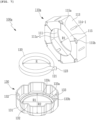
- FIG. 7 is an exploded skew drawing illustrating separately the elements of the anti-loosening spring nut 100a according to a second embodiment of the present invention
- FIG. 8 is a side section illustrating the cross section of the anti-loosening spring nut 100a according to a second embodiment of the present invention when fastened to a bolt 10 together with a nut 20.
- the anti-loosening spring nut 100a comprises a ratchet external casing 110a, and an internal casing 130 which is accommodated within the ratchet external casing 110a and which itself accommodates a female thread spring 120.
- the anti-loosening spring nut 100a of the second embodiment when compared to the anti-loosening spring nut 100 of the first and preferred embodiment, further comprises an internal casing 130.
- the anti-loosening spring nut 100a is fastened beneath a nut 20 using an electric tool such as a rechargeable electric screwdriver or a nut runner, and the ratchet external casing 110a spins without traction beyond a tightening torque limit, providing a benefit of further improved tool adaptability.
- female thread spring 120 of the second embodiment has the same elements as that of the first and preferred embodiment, detailed description thereof will be omitted hereafter.
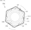
- the depression depth of the short pushing projection 114-1 formed on the side face 113 is less than that of the pushing projection 114.
- the bolt insertion hole 111a formed on the bottom plate 111 of the anti-loosening spring nut 100 of the first and preferred embodiment is formed to correspond to the outer diameter of the bolt 10
- the hub insertion hole 111a-1 formed on the bottom plate 111 of the anti-loosening spring nut 100a according to the second embodiment is formed to have a diameter R1 greater than that of the bolt insertion hole 111a.
- the internal casing 130 is accommodated within the external casing 110, and itself accommodates the female thread spring 120.
- the internal casing is formed in the shape of an enclosure whose top is open, and comprises an internal casing wall 131 and a bearing floor plate 133.
- the internal casing wall 131 may be formed in various shapes such as circular or polygonal, insofar as it is able to accommodate the female thread spring 120. Along the face of the internal casing wall 131 are provided a plurality of receiving projections 132 which are depressedly formed inward in a number and at intervals corresponding to the short pushing projections 114-1.
- the plurality of receiving projections 132 are projectingly formed toward the periphery of the female thread spring 120, supporting the female thread spring 120 so that the female thread spring 120 may be aligned with the centers of the ratchet external casing 110a and the internal casing 130.
- the receiving projection 132 is pressed against by the short pushing projection 114-1 when the ratchet external casing 110a is rotated in the forward or reverse direction using a standard tool, and in turn presses against the upper catching loop end 121 or the lower catching loop end 123 of the female thread spring 120.
- This causes the upper catching loop end 121 and the lower catching loop end 123 to be spread apart, expanding the inner diameter R' of the female thread spring 120 relative to the initial inner diameter R and facilitating fastening to or loosening from the bolt 10.
- the bearing floor plate 133 is disposed to overlap the bottom plate 111 of the ratchet external casing 110a.
- the bearing floor plate 133 is formed with a surface area allowing for overlapping the bottom plate 111.
- a projecting hub 133a which is exposed outward through the hub insertion hole 111a-1 of the bottom plate 111 is steppedly formed.
- the projecting hub 133a is formed to steppedly extend from the bearing floor plate 133 by the height of a step 133b, and projects out of the hub insertion hole 111a-1 by a certain distance d1.
- a gap of a certain height d2 is formed between the bearing floor plate 133 and the bottom plate 111, and a gap of a certain height W is formed between the hub insertion hole 111a-1 and the projecting hub 133a as well.
- the external diameter R1 of the hub insertion hole 111a-1 is formed to be identical to the internal diameter R1 of the bearing floor plate 133, and the internal bolt insertion hole 133c formed on the projection hub 133a is formed to have a diameter corresponding to the external diameter of the bolt 10.
- the corner a between the projecting hub 133a and step 133b, and the corner b between the internal casing wall 131 and the bearing floor plate 133 are formed as curved faces.
- This shape of the bearing floor plate 133 and projecting hub 133a is intended to minimize friction between the ratchet external casing 110a and the projecting hub 133a and bearing floor plate 133 once the anti-loosening spring nut 100a has been fastened beneath the nut 20, allowing the rachet external casing 110a to spin without traction.
- the depression depth h1 of the short pushing projection 114-1 is less than the depression depth h2 of the receiving projection 132.
- the short pushing projection 114-1 is formed to a depth such that, in a state where the anti-loosening spring nut 100a has been fastened beneath the nut 20 and the projecting hub 133a is in contact with the bottom face of the nut 20 (that is, after the tightening torque limit has been reached by rotating the anti-loosening spring nut 100a with a tool), if torque in the fastening direction continues to be applied by the tool, the short pushing projection 114-1 can pass over and move beyond the receiving projection 132.
- the projecting hub 133a is in close contact with the bottom face of the nut 20, securing the internal casing 130 in position, while the ratchet external casing 110a is separated from the projecting hub 133a and the hub insertion hole 111a-1 by a gap W and from the bearing floor plate 133 and bottom plate 111 by a gap d2. Therefore, the ratchet external casing 110a performs a ratchet function wherein the ratchet external casing 110a spins without traction as the the short pushing projection 114-1 passes over the receiving projection 132.
- the anti-loosening spring nut accommodates a female thread spring used to prevent loosening of a bolt within an external casing which can be manipulated using a standard tool, and pushing projections formed on the inner wall faces of the external casing push against an upper catching loop end and a lower catching loop end of the female thread spring, causing the external casing to become fastened to or loosened from the bolt.
- the present invention has the advantage of being able to be fastened quickly to a bolt using a standard tool while maintaining the anti-loosening function of a female thread spring.
- the anti-loosening spring nut of the present invention provides a ratchet function by adding an internal casing and providing a receiving projection which is pushed against by a pushing projection, causing the external casing to spin without traction once the anti-loosening spring nut has been fastened beneath the nut.
- the present invention has enhanced adaptability to standard tools, providing the benefit of faster installation.
- the present invention as industrial applicability for coupling two objects by fastening in various fields including general industrial machinery, such as assembly of automotive components, assembly of electronic components, assembly of furniture, and assembly of structures at construction sites.
Landscapes
- Engineering & Computer Science (AREA)
- General Engineering & Computer Science (AREA)
- Mechanical Engineering (AREA)
- Bolts, Nuts, And Washers (AREA)
- Clamps And Clips (AREA)
- Springs (AREA)
Applications Claiming Priority (2)
| Application Number | Priority Date | Filing Date | Title |
|---|---|---|---|
| KR1020220006833A KR102419470B1 (ko) | 2022-01-17 | 2022-01-17 | 풀림방지스프링너트 |
| PCT/KR2022/010708 WO2023136411A1 (fr) | 2022-01-17 | 2022-07-21 | Écrou à ressort antidesserrage |
Publications (2)
| Publication Number | Publication Date |
|---|---|
| EP4467824A1 true EP4467824A1 (fr) | 2024-11-27 |
| EP4467824A4 EP4467824A4 (fr) | 2025-11-19 |
Family
ID=82407255
Family Applications (1)
| Application Number | Title | Priority Date | Filing Date |
|---|---|---|---|
| EP22920744.4A Pending EP4467824A4 (fr) | 2022-01-17 | 2022-07-21 | Écrou à ressort antidesserrage |
Country Status (6)
| Country | Link |
|---|---|
| US (1) | US20250243892A1 (fr) |
| EP (1) | EP4467824A4 (fr) |
| JP (1) | JP7777680B2 (fr) |
| KR (1) | KR102419470B1 (fr) |
| CN (1) | CN118202162A (fr) |
| WO (1) | WO2023136411A1 (fr) |
Families Citing this family (1)
| Publication number | Priority date | Publication date | Assignee | Title |
|---|---|---|---|---|
| KR102419470B1 (ko) * | 2022-01-17 | 2022-07-08 | 문상열 | 풀림방지스프링너트 |
Family Cites Families (7)
| Publication number | Priority date | Publication date | Assignee | Title |
|---|---|---|---|---|
| JPWO2005121570A1 (ja) * | 2004-06-07 | 2008-04-10 | 泰治郎 添田 | 脱落防止具および緩み止めナット |
| JP2018004067A (ja) * | 2016-06-27 | 2018-01-11 | 鈴木 康之 | 締結ナットの脱落防止装置 |
| KR101907342B1 (ko) | 2018-01-10 | 2018-10-11 | 한경섭 | 풀림방지너트 |
| CN108825636A (zh) * | 2018-08-28 | 2018-11-16 | 四川中伦精密机械有限公司 | 复合嵌簧式防松螺母 |
| KR102289859B1 (ko) * | 2020-05-26 | 2021-08-13 | 문상열 | 풀림방지너트 |
| KR102301433B1 (ko) * | 2020-08-16 | 2021-09-23 | (주)평우로지스 | 풀림 방지 너트 |
| KR102419470B1 (ko) * | 2022-01-17 | 2022-07-08 | 문상열 | 풀림방지스프링너트 |
-
2022
- 2022-01-17 KR KR1020220006833A patent/KR102419470B1/ko active Active
- 2022-07-21 WO PCT/KR2022/010708 patent/WO2023136411A1/fr not_active Ceased
- 2022-07-21 US US18/702,268 patent/US20250243892A1/en active Pending
- 2022-07-21 JP JP2024527108A patent/JP7777680B2/ja active Active
- 2022-07-21 EP EP22920744.4A patent/EP4467824A4/fr active Pending
- 2022-07-21 CN CN202280073719.0A patent/CN118202162A/zh active Pending
Also Published As
| Publication number | Publication date |
|---|---|
| KR102419470B1 (ko) | 2022-07-08 |
| WO2023136411A1 (fr) | 2023-07-20 |
| EP4467824A4 (fr) | 2025-11-19 |
| JP2024541302A (ja) | 2024-11-08 |
| US20250243892A1 (en) | 2025-07-31 |
| CN118202162A (zh) | 2024-06-14 |
| JP7777680B2 (ja) | 2025-11-28 |
Similar Documents
| Publication | Publication Date | Title |
|---|---|---|
| US3294140A (en) | Panel fastener | |
| US9732783B2 (en) | Anti-loosening bolt assembly | |
| US5688091A (en) | Self-locking fastener with captive washer | |
| US3561516A (en) | Safety bolt | |
| US5606753A (en) | Fixing device with a locking mechanism | |
| US10486461B1 (en) | Wheel lock with central expander | |
| EP2912327B1 (fr) | Ensemble d'écrou de rochet | |
| US5482417A (en) | Cam and wedge-type self-locking mechanism | |
| US20140348613A1 (en) | Nut And/Or Bolt Head With Jackscrew Actuated Lock Washer Stack | |
| EP3587842B1 (fr) | Structure de fixation | |
| US5302066A (en) | Locking fastener | |
| KR20110085832A (ko) | 세이퍼락 너트 | |
| US5080544A (en) | Adjustable locknut assembly | |
| KR102301404B1 (ko) | 풀림 방지용 스프링이 결합된 볼트 | |
| KR102048264B1 (ko) | 풀림방지 너트 | |
| US3404716A (en) | Self-locking fastener | |
| US5082406A (en) | Self locking panel fastener with device for visually indicating whether fastener is locked | |
| EP4467824A1 (fr) | Écrou à ressort antidesserrage | |
| KR101874773B1 (ko) | 그렙너트 | |
| WO2020099896A1 (fr) | Élément de fixation | |
| US3683988A (en) | Positive lock structural fastener | |
| AU2019281801A1 (en) | Wheel lock with central expander | |
| EP4121662B1 (fr) | Ensemble fixation fileté à verrouillage | |
| EP0321316A2 (fr) | Rondelle d'arrêt | |
| KR20220022925A (ko) | 풀림 기능을 갖춘 풀림방지 너트 |
Legal Events
| Date | Code | Title | Description |
|---|---|---|---|
| STAA | Information on the status of an ep patent application or granted ep patent |
Free format text: STATUS: THE INTERNATIONAL PUBLICATION HAS BEEN MADE |
|
| PUAI | Public reference made under article 153(3) epc to a published international application that has entered the european phase |
Free format text: ORIGINAL CODE: 0009012 |
|
| STAA | Information on the status of an ep patent application or granted ep patent |
Free format text: STATUS: REQUEST FOR EXAMINATION WAS MADE |
|
| 17P | Request for examination filed |
Effective date: 20240514 |
|
| AK | Designated contracting states |
Kind code of ref document: A1 Designated state(s): AL AT BE BG CH CY CZ DE DK EE ES FI FR GB GR HR HU IE IS IT LI LT LU LV MC MK MT NL NO PL PT RO RS SE SI SK SM TR |
|
| DAV | Request for validation of the european patent (deleted) | ||
| DAX | Request for extension of the european patent (deleted) | ||
| A4 | Supplementary search report drawn up and despatched |
Effective date: 20251022 |
|
| RIC1 | Information provided on ipc code assigned before grant |
Ipc: F16B 39/14 20060101AFI20251016BHEP Ipc: F16B 39/20 20060101ALI20251016BHEP |