EP4468096A1 - Bearbeitungsverfahren und bearbeitungsvorrichtung - Google Patents
Bearbeitungsverfahren und bearbeitungsvorrichtung Download PDFInfo
- Publication number
- EP4468096A1 EP4468096A1 EP24174182.6A EP24174182A EP4468096A1 EP 4468096 A1 EP4468096 A1 EP 4468096A1 EP 24174182 A EP24174182 A EP 24174182A EP 4468096 A1 EP4468096 A1 EP 4468096A1
- Authority
- EP
- European Patent Office
- Prior art keywords
- machining
- thrust
- threshold
- feed
- spindle
- Prior art date
- Legal status (The legal status is an assumption and is not a legal conclusion. Google has not performed a legal analysis and makes no representation as to the accuracy of the status listed.)
- Pending
Links
Images




Classifications
-
- B—PERFORMING OPERATIONS; TRANSPORTING
- B23—MACHINE TOOLS; METAL-WORKING NOT OTHERWISE PROVIDED FOR
- B23Q—DETAILS, COMPONENTS, OR ACCESSORIES FOR MACHINE TOOLS, e.g. ARRANGEMENTS FOR COPYING OR CONTROLLING; MACHINE TOOLS IN GENERAL CHARACTERISED BY THE CONSTRUCTION OF PARTICULAR DETAILS OR COMPONENTS; COMBINATIONS OR ASSOCIATIONS OF METAL-WORKING MACHINES, NOT DIRECTED TO A PARTICULAR RESULT
- B23Q17/00—Arrangements for observing, indicating or measuring on machine tools
- B23Q17/09—Arrangements for observing, indicating or measuring on machine tools for indicating or measuring cutting pressure or for determining cutting-tool condition, e.g. cutting ability, load on tool
- B23Q17/0952—Arrangements for observing, indicating or measuring on machine tools for indicating or measuring cutting pressure or for determining cutting-tool condition, e.g. cutting ability, load on tool during machining
- B23Q17/0957—Detection of tool breakage
-
- B—PERFORMING OPERATIONS; TRANSPORTING
- B23—MACHINE TOOLS; METAL-WORKING NOT OTHERWISE PROVIDED FOR
- B23Q—DETAILS, COMPONENTS, OR ACCESSORIES FOR MACHINE TOOLS, e.g. ARRANGEMENTS FOR COPYING OR CONTROLLING; MACHINE TOOLS IN GENERAL CHARACTERISED BY THE CONSTRUCTION OF PARTICULAR DETAILS OR COMPONENTS; COMBINATIONS OR ASSOCIATIONS OF METAL-WORKING MACHINES, NOT DIRECTED TO A PARTICULAR RESULT
- B23Q17/00—Arrangements for observing, indicating or measuring on machine tools
-
- B—PERFORMING OPERATIONS; TRANSPORTING
- B23—MACHINE TOOLS; METAL-WORKING NOT OTHERWISE PROVIDED FOR
- B23Q—DETAILS, COMPONENTS, OR ACCESSORIES FOR MACHINE TOOLS, e.g. ARRANGEMENTS FOR COPYING OR CONTROLLING; MACHINE TOOLS IN GENERAL CHARACTERISED BY THE CONSTRUCTION OF PARTICULAR DETAILS OR COMPONENTS; COMBINATIONS OR ASSOCIATIONS OF METAL-WORKING MACHINES, NOT DIRECTED TO A PARTICULAR RESULT
- B23Q15/00—Automatic control or regulation of feed movement, cutting velocity or position of tool or work
- B23Q15/007—Automatic control or regulation of feed movement, cutting velocity or position of tool or work while the tool acts upon the workpiece
- B23Q15/013—Control or regulation of feed movement
-
- B—PERFORMING OPERATIONS; TRANSPORTING
- B23—MACHINE TOOLS; METAL-WORKING NOT OTHERWISE PROVIDED FOR
- B23Q—DETAILS, COMPONENTS, OR ACCESSORIES FOR MACHINE TOOLS, e.g. ARRANGEMENTS FOR COPYING OR CONTROLLING; MACHINE TOOLS IN GENERAL CHARACTERISED BY THE CONSTRUCTION OF PARTICULAR DETAILS OR COMPONENTS; COMBINATIONS OR ASSOCIATIONS OF METAL-WORKING MACHINES, NOT DIRECTED TO A PARTICULAR RESULT
- B23Q17/00—Arrangements for observing, indicating or measuring on machine tools
- B23Q17/002—Arrangements for observing, indicating or measuring on machine tools for indicating or measuring the holding action of work or tool holders
- B23Q17/005—Arrangements for observing, indicating or measuring on machine tools for indicating or measuring the holding action of work or tool holders by measuring a force, a pressure or a deformation
-
- B—PERFORMING OPERATIONS; TRANSPORTING
- B23—MACHINE TOOLS; METAL-WORKING NOT OTHERWISE PROVIDED FOR
- B23Q—DETAILS, COMPONENTS, OR ACCESSORIES FOR MACHINE TOOLS, e.g. ARRANGEMENTS FOR COPYING OR CONTROLLING; MACHINE TOOLS IN GENERAL CHARACTERISED BY THE CONSTRUCTION OF PARTICULAR DETAILS OR COMPONENTS; COMBINATIONS OR ASSOCIATIONS OF METAL-WORKING MACHINES, NOT DIRECTED TO A PARTICULAR RESULT
- B23Q17/00—Arrangements for observing, indicating or measuring on machine tools
- B23Q17/09—Arrangements for observing, indicating or measuring on machine tools for indicating or measuring cutting pressure or for determining cutting-tool condition, e.g. cutting ability, load on tool
- B23Q17/0952—Arrangements for observing, indicating or measuring on machine tools for indicating or measuring cutting pressure or for determining cutting-tool condition, e.g. cutting ability, load on tool during machining
- B23Q17/0966—Arrangements for observing, indicating or measuring on machine tools for indicating or measuring cutting pressure or for determining cutting-tool condition, e.g. cutting ability, load on tool during machining by measuring a force on parts of the machine other than a motor
-
- G—PHYSICS
- G05—CONTROLLING; REGULATING
- G05B—CONTROL OR REGULATING SYSTEMS IN GENERAL; FUNCTIONAL ELEMENTS OF SUCH SYSTEMS; MONITORING OR TESTING ARRANGEMENTS FOR SUCH SYSTEMS OR ELEMENTS
- G05B19/00—Program-control systems
- G05B19/02—Program-control systems electric
- G05B19/18—Numerical control [NC], i.e. automatically operating machines, in particular machine tools, e.g. in a manufacturing environment, so as to execute positioning, movement or co-ordinated operations by means of program data in numerical form
- G05B19/406—Numerical control [NC], i.e. automatically operating machines, in particular machine tools, e.g. in a manufacturing environment, so as to execute positioning, movement or co-ordinated operations by means of program data in numerical form characterised by monitoring or safety
- G05B19/4065—Monitoring tool breakage, life or condition
-
- B—PERFORMING OPERATIONS; TRANSPORTING
- B23—MACHINE TOOLS; METAL-WORKING NOT OTHERWISE PROVIDED FOR
- B23Q—DETAILS, COMPONENTS, OR ACCESSORIES FOR MACHINE TOOLS, e.g. ARRANGEMENTS FOR COPYING OR CONTROLLING; MACHINE TOOLS IN GENERAL CHARACTERISED BY THE CONSTRUCTION OF PARTICULAR DETAILS OR COMPONENTS; COMBINATIONS OR ASSOCIATIONS OF METAL-WORKING MACHINES, NOT DIRECTED TO A PARTICULAR RESULT
- B23Q2717/00—Arrangements for indicating or measuring
- B23Q2717/006—Arrangements for indicating or measuring in milling machines
-
- G—PHYSICS
- G05—CONTROLLING; REGULATING
- G05B—CONTROL OR REGULATING SYSTEMS IN GENERAL; FUNCTIONAL ELEMENTS OF SUCH SYSTEMS; MONITORING OR TESTING ARRANGEMENTS FOR SUCH SYSTEMS OR ELEMENTS
- G05B2219/00—Program-control systems
- G05B2219/30—Nc systems
- G05B2219/37—Measurements
- G05B2219/37245—Breakage tool, failure
-
- G—PHYSICS
- G05—CONTROLLING; REGULATING
- G05B—CONTROL OR REGULATING SYSTEMS IN GENERAL; FUNCTIONAL ELEMENTS OF SUCH SYSTEMS; MONITORING OR TESTING ARRANGEMENTS FOR SUCH SYSTEMS OR ELEMENTS
- G05B2219/00—Program-control systems
- G05B2219/30—Nc systems
- G05B2219/37—Measurements
- G05B2219/37246—Compare estimated torques of different axis with reference for breakage
-
- G—PHYSICS
- G05—CONTROLLING; REGULATING
- G05B—CONTROL OR REGULATING SYSTEMS IN GENERAL; FUNCTIONAL ELEMENTS OF SUCH SYSTEMS; MONITORING OR TESTING ARRANGEMENTS FOR SUCH SYSTEMS OR ELEMENTS
- G05B2219/00—Program-control systems
- G05B2219/30—Nc systems
- G05B2219/37—Measurements
- G05B2219/37252—Life of tool, service life, decay, wear estimation
-
- G—PHYSICS
- G05—CONTROLLING; REGULATING
- G05B—CONTROL OR REGULATING SYSTEMS IN GENERAL; FUNCTIONAL ELEMENTS OF SUCH SYSTEMS; MONITORING OR TESTING ARRANGEMENTS FOR SUCH SYSTEMS OR ELEMENTS
- G05B2219/00—Program-control systems
- G05B2219/30—Nc systems
- G05B2219/50—Machine tool, machine tool null till machine tool work handling
- G05B2219/50095—On tool breakage return to a reference then follow already machined path
-
- G—PHYSICS
- G05—CONTROLLING; REGULATING
- G05B—CONTROL OR REGULATING SYSTEMS IN GENERAL; FUNCTIONAL ELEMENTS OF SUCH SYSTEMS; MONITORING OR TESTING ARRANGEMENTS FOR SUCH SYSTEMS OR ELEMENTS
- G05B2219/00—Program-control systems
- G05B2219/30—Nc systems
- G05B2219/50—Machine tool, machine tool null till machine tool work handling
- G05B2219/50205—On tool breakage stop machine
Definitions
- the present invention relates to a machining method and a machining apparatus.
- a tool breakage detection method in a NC drilling device that feeds a drilling tool by a servo motor controlled by a servo amplifier is known (for example, JP-A-H05-329750 ).
- breakage of the tool is detected when the duration of the state, in which the input torque signal voltage exceeds the threshold voltage, exceeds a predetermined time.
- the thrust of the feed axis may vary depending on the feed coordinates.
- An object of the present invention is to detect a tool breakage or a thrust variation at a machining point when machining a small diameter hole.
- a first aspect of the present invention provides a machining method, including:
- a second aspect of the present invention provides a machining apparatus, including:
- the threshold includes a breakage threshold and a return threshold.
- the machining condition is defined by, for example, a machining feed start point, a machining end point, a feed speed, a spindle rotation speed, and a tool number.
- the reference thrust may be replaced by a reference torque.
- the machining thrust may be replaced by a machining torque.
- the filter is, for example, a low-pass filter.
- the delay time is a time from when the original signal waveform rises to when the filtered signal waveform rises.
- the original signal waveform includes a reference thrust and a machining thrust.
- the comparison between the machining thrust and the threshold may be started when a delay time elapses from when the tool comes into contact with the workpiece.
- the machining start point is the position of the tool or spindle when the tool comes into contact with the workpiece as the tool approaches the workpiece.
- a machining start time is a time when the tool comes into contact with the workpiece as the tool approaches the workpiece.
- the delay time is determined by a time constant determined by the filter.
- the increment of the feed coordinate corresponding to the delay time is defined as a delay coordinate.
- the delay coordinate is determined by the delay time, the feed speed, and the acceleration.
- the comparison between the machining thrust and the threshold may be started from the coordinates obtained by adding the delay coordinates from the feed coordinates of the machining start point, which is the position at which the tool comes into contact with the workpiece.
- the breakage threshold and the return threshold may be determined based on the environmental temperature, the temperature of the machining apparatus, the cumulative operation time, and the material of the workpiece. Further, the breakage offset amount and the return offset amount may be determined based on the environmental temperature, the temperature of the machining apparatus, the cumulative operation time, and the material of the workpiece. The breakage threshold, the return threshold, the breakage offset amount, and the return offset amount may be determined based on a function using the environmental temperature, the temperature of the machining apparatus, the cumulative operation time, and the material of the workpiece as arguments.
- Examples of the machining method include drilling, tapping, milling, and end milling.
- the machining method can be particularly suitably applied to drilling or tapping.
- the machining apparatus is, for example, a machining center or a drilling machine.
- the drilling machine is, for example, a tapping machine.
- the spindle is rotatably supported by the spindle head or the ram.
- the spindle is fed by a feed device via the spindle head or the ram.
- the feed device is, for example, a ball screw-motor mechanism, a cylinder, or a linear motor.
- the motor or the linear motor may be a servo motor.
- the cylinder is, for example, an air cylinder or an electric cylinder.
- the thrust measuring device is, for example, a torque sensor, a motor amplifier, or a strain gauge.
- the motor amplifier is, for example, a servo amplifier.
- the thrust measuring device may be a torque measuring device.
- the strain gauge may be mounted on the ram or the feed table.
- the present invention enables to detect a tool breakage or a thrust variation at a machining point when machining a small diameter hole.
- a drilling machine 10 includes a feed device 11, a ram 16, a spindle 17, a spindle motor 18, a ram guide 19, and a control device 30.
- a direction in which the spindle 17 extends is defined as a Z direction.
- a positive Z direction is defined as a direction in which the spindle 17 is separated from a workpiece 3.
- the feed device 11 includes a feed motor 12, a feed screw (feed shaft) 13, and a feed table 15.
- the feed motor 12 is connected to the feed screw 13.
- the feed motor 12 reciprocates the feed table 15 in the Z direction via the feed screw 13.
- the feed motor 12 is, for example, a servo motor.
- the ram 16 is connected to the feed table 15.
- the ram 16 rotatably supports the spindle 17.
- the ram 16 is guided by the ram guide 19.
- a tool 1 is attached to the spindle 17.
- the spindle 17 is connected to the spindle motor 18.
- the control device 30 includes a storage device 31, a feed control unit 35, a determination unit 37, and a threshold determination unit 39.
- the control device 30 includes, for example, a servo amplifier and a programmable controller.
- the programmable controller is a numerical controller.
- the programmable controller includes a sequence control device.
- the storage device 31 stores a reference torque (reference thrust) Tr0, a machining torque (machining thrust) Tr1, a machining program 31c, a breakage threshold Th1, a return threshold Th2, a breakage determination time tm0, a return determination time tm2, a breakage offset amount o1, and a return offset amount o2.
- the storage device 31 may store an origin Z0, a machining start point Z2, and a machining start time t2.
- the machining program 31c includes a machining feed start point Z1 and a machining end point Z3.
- the machining program 31c may include a feed speed (not shown), a spindle rotational speed (not shown), and a tool number (not shown).
- the machining conditions are defined by, for example, the machining feed start point Z1, the machining end point Z3, the feed speed (not shown), the spindle rotational speed (not shown), and the tool number (not shown).
- the machining program 31c includes, for example, the following four steps.
- the spindle motor 18 rotates the spindle 17 at the spindle rotational speed.
- the feed motor 12 rapidly feeds the spindle 17 to the origin 50.
- the reference torque Tr0 is a torque (thrust) Tr of the feed motor 12 with respect to the coordinate (feed coordinate) Z when the tool 1 does not machine a workpiece 3.
- the torque Tr is, for example, an actual measured value (unit: Nm) or a ratio to a rated torque (unit: %).
- the reference torque Tr0 may include an actual reference torque Tr0a and a processed reference torque TrOb.
- the actual reference torque Tr0a is the actual torque with respect to the coordinate Z.
- the processed reference torque TrOb is obtained by filtering the actual reference torque Tr0a.
- the reference torque Tr0 may include an actual reference torque TrOc, a processed reference torque Tr0d, and a coordinate Za.
- the actual reference torque TrOc is an actual torque Tr with respect to a time (machining time) t.
- the processed reference torque TrOd is obtained by filtering the actual reference torque TrOc.
- the reference torque Tr0 may include a rapid feed torque TrOj.
- the rapid feed torque TrOj is a torque Tr when the feed table 15 is rapidly fed.
- the coordinate Za is a coordinate Z with respect to time t.
- the storage device 31 may temporarily store the reference torque Tr0 in order to calculate the breakage threshold Th1 or the return threshold Th2.
- the machining torque Tr1 is the torque Tr of the feed motor 12 with respect to the coordinate Z when the tool 1 has machined the workpiece 3.
- the machining torque Tr1 may include an actual machining torque Tr1a and a processed machining torque Tr1b.
- the actual machining torque Tr1a is an actual torque with respect to the coordinate Z.
- the processed machining torque Tr1b is obtained by filtering the actual machining torque Tr1a.
- the machining torque Tr1 may include actual machining torques Trie, Trie, Trig, processed machining torques Tr1d, Tr1f, Tr1h, and a coordinate Za.
- the actual machining torques Trie, Trie, Trig each is an actual torque Tr with respect to time t.
- the processed machining torques Tr1d, Tr1f, Tr1h are obtained by filtering the actual machining torques Trie, Trie, Trig, respectively.
- the machining torque Tr1 may include a rapid feed torque Tr1j.
- the rapid feed torque Tr1j is a torque Tr when the feed table 15 is rapidly fed.
- the storage device 31 does not need to store the actual machining torques Tr1a, Trie, Trie, Trig or the rapid feed torque Tr1j. Further, the storage device 31 may temporarily store the machining torque Tr1.
- the breakage threshold Th1 is the threshold of the torque Tr with respect to the coordinate Z.
- a machining feed length (Z3 - Z1) is divided into a plurality of sections 55 at equal intervals.
- the breakage thresholds Th1 are set for each of the section 55.
- the machining feed length is a distance at which the spindle 17 is fed, which is determined by the machining program 31c.
- the length of the section 55 may be very small. In an extreme case, the length of the section 55 may be the smallest unit of the feed coordinate Z.
- the breakage threshold Th1 is set between the reference torque Tr0 and the machining torque Tr1 when the tool 1 is properly machining the workpiece 3.
- the tool 1 properly machines the workpiece 3 when the tool 1 machines the workpiece 3 without breakage of the tool 1 or without clogging the drilling machine 10 by the chips generated during the machining.
- the return threshold Th2 is a threshold of the torque Tr with respect to the coordinate Z.
- the return threshold Th2 is greater than the breakage threshold Th1.
- the return threshold Th2 is set between the machining torque Tr1 when the tool 1 is properly machining the workpiece 3 and the machining torque Tr1 when the tool 1 is broken. Otherwise, the return threshold Th2 is substantially the same as the breakage threshold Th1.
- the breakage determination time tm0, the return determination time tm2, the breakage offset amount o1, and the return offset amount o2 are inputted from the outside in advance.
- breakage threshold Th1 and the return threshold Th2 the breakage determination time tm0, and the return determination time tm2 may be omitted. Either the breakage offset amount o1 or the return offset amount o2 may be omitted.
- the feed control unit 35 includes a filtering unit 35a, a torque measurement unit (thrust measurement device) 35b, and a feed unit 35c.
- the filtering unit 35a performs filtering on the actual reference torque TrOa, TrOc to obtain the filtered reference torque TrOb, TrOd.
- the filtering unit 35a performs filtering on the actual machining torque Tr1a, Trie, Trie, Trig to obtain the filtered machining torque Trib, Tr1d, Tr1f, Tr1h.
- the filter is, for example, a low-pass filter.
- the actual reference torque TrOa, TrOc and the actual machining torque Tr1a, Trie, Trie, Trig vary depending on the intermittent contact between the cutting edge of the tool 1 and the workpiece 3, the formation and separation of the built-up edge, the generation of chips, the frictional resistance between the chips and the workpiece 3 or the tool 1, the feed resistance of the feed device 11 or the ram 16, and the deflection of the ram 16.
- the actual reference torque TrOa, TrOc and the actual machining torque Tr1a, Trie, Trie, Trig vibrate at higher frequencies.
- the filtered reference torque TrOb, TrOd and the filtered machining torque Trib, Tr1d, Tr1f, Tr1h have a smooth wave shape in which a high-frequency component is removed.
- the filtering unit 35a stores the filtered reference torque TrOb, TrOd and the filtered machining torque Tr1b, Tr1d, Tr1f, Tr1h in the storage device 31.
- the torque measurement unit 35b measures the coordinate Z and the torque Tr with respect to the time t, and stores them in the storage device 31.
- the feed unit 35c provides power to and rotates the feed motor 12.
- the feed unit 35c feedback-controls the feed motor 12.
- the feed unit 35c controls the feed motor 12 and the spindle motor 18 in accordance with the machining program 31c.
- the determination unit 37 compares the filtered machining torque Trib, Tr1d, Tr1f, Tr1h with the breakage threshold Th1 and the return threshold Th2.
- the determination unit 37 may include a timer 37a.
- the timer 37a measures a low torque time (low thrust time) tm1 in which the machining torque Tr1 equal to or lower than the breakage threshold Th1 continues.
- the timer 37a measures an excess torque time (excess thrust time) tm3 in which the machining torque Tr1 equal to or larger than the return threshold Th2 continues.
- the threshold determination unit 39 determines the breakage threshold Th1 and the breakage threshold Th2 based on the filtered reference torque TrOb, Tr0d, the breakage offset amount o1, and the return offset amount o2. Specifically, as shown in FIG. 2 , the threshold determination unit 39 divides the machining feed width (Z3 - Z1) into a plurality of sections 55 by a predetermined number of divisions or section width. Then, the threshold determination unit 39 adds the breakage offset value o1 to the representative value of the filtered reference torque TrOb for each section 55 to obtain the breakage threshold Th1. The threshold determination unit 39 adds the return offset amount o2 to the representative values of the filtered reference torque TrOb for each section 55 to obtain the return threshold Th2.
- the representative value is, for example, an average value, a maximum value, a minimum value, or an initial value of the section 55.
- the threshold determination unit 39 may determine the breakage threshold Th1 and the return threshold Th2 based on a function using an environmental temperature, a temperature of the machining apparatus, a cumulative operation time, and a material of the workpiece as an argument.
- the storage device 31 may store the environmental temperature, the temperature of the machining apparatus, the cumulative operation time, and the material of the workpiece.
- the threshold determination unit 39 may determine the breakage offset amount o1 and the return offset amount o2 based on the environmental temperature, the temperature of the machining apparatus, the cumulative operation time, and the material of the workpiece.
- step S1 the drilling machine 10 is operated in accordance with the machining program 31c without the workpiece 3 being installed.
- the torque measurement unit 35b acquires the reference torque Tr0 with respect to the coordinate Z.
- the threshold determination unit 39 determines the breakage threshold Th1 and the return threshold Th2, and stores them in the storage device 31.
- step S2 the spindle 17 is rapidly fed until the tool 1 reaches the machining feed start point 51.
- step S3 the spindle 17 is fed while machining until the tool 1 reaches the machining end point 53.
- the monitoring process of steps S4 to S10 is always repeatedly executed.
- the torque measurement unit 35b constantly acquires the machining torque Tr1 and the coordinate Z.
- the determination unit 37 constantly monitors the machining torque Tr1.
- step S4 when the machining torque Tr1 becomes equal to or smaller than the breakage threshold Th1, the process proceeds to the step S5. Otherwise, the process proceeds to the step S7.
- step S5 the timer 37a measures the low torque time tm1 (see FIG. 6 ).
- step S6 the determination unit 37 transmits an alarm. Then, the process proceeds to the step S11.
- step S7 when the machining torque Tr1 becomes equal to or larger than the return threshold Th2, the process proceeds to the step S8. Otherwise, the process proceeds to the step S10.
- step S8 when the excess torque time tm3 becomes equal to or longer than the return determination time tm2, the process proceeds to the step S9. Otherwise, the process proceeds to the step S10.
- step S9 the feed unit 35c once rapidly pulls back the spindle 17 to the machining feed start point 51.
- the pullback position Z5 is a position in which the spindle 17 is pulled back. Then, the process returns to the step S3.
- step S10 when the tool 1 reaches the machining end point 53, the process proceeds to the step S11. Otherwise, the process returns to the step S3. In step S11, the spindle 17 rapidly returns to the origin 50.
- the step S1 may be performed periodically. For example, the step S1 may be performed every time the actual machining of the steps S2 to S11 is performed specified number of times (for example, 5000 times). Alternatively, the step S1 may be performed every specified period (for example, 30 minutes).
- steps S7 to S9 may be omitted.
- the steps S4 to S6 may be omitted.
- the step S5 is omitted.
- the step S8 is omitted.
- step S1 the drilling machine 10 is driven under the same conditions as the actual machining except that the workpiece 3 is not installed. That is, the drilling machine 10 operates in accordance with the machining program 31c.
- t0 ⁇ t ⁇ t1 indicates a rapid feed until the tool 1 reaches the machining feed start point 51 from the origin 50. During this time, the rapid feed torque TrOj exhibits a higher peak.
- the spindle 17 is fed while machining from the machining feed start point 51 to the machining end point 53.
- the filtering unit 35a filters the actual reference torque TrOc to obtain the filtered reference torque TrOd.
- the filtering unit 35a stores the actual reference torque TrOc, the filtered reference torque Tr0d, and the coordinate Za in the storage device 31.
- the threshold determination unit 39 removes the rapid feed torque TrOj when determining the breakage threshold Th1 and the return threshold Th2. In other words, in Z0 ⁇ Z ⁇ Z1, the breakage threshold Th1 and the return threshold Th2 are not given.
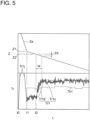
- the actual machining process will be described with reference to FIGs. 5 to 7 .
- the actual machining corresponds to steps S2 to S11.
- FIG. 5 shows the machining torque Tr1 and the coordinate Za when the machining proceeds properly.
- the step S2 is performed.
- step S3 is then performed. Then, the spindle 17 is fed while machining with the machining end point 53 as an end point.
- the tool 1 contacts the workpiece 3, and the actual machining torque Tr1c rapidly increases.
- the position at this time is referred to as a machining start point 52 (see FIG. 1 ).
- the coordinate Z of the machining start point 52 is Z2.
- the filtered machining torque Tr1d increases later than the actual machining torque Tr1c.
- the machining start time t2 is when the tool 1 reaches the machining start point 52.
- the delay time td is determined by a time constant determined by the filters.
- the increment of the feed coordinate corresponding to the delay time td is referred to as a delay coordinate (delay distance) Zd.
- the delay coordinate Zd is determined by the delay time td, the feed rate (not shown), and the acceleration (not shown).
- the machining start time t2 is determined by the coordinate Z1, the coordinate Z2 of the machining start point 52, the feed rate (not shown), and the accelerations (not shown).
- FIG. 6 shows the machining torque Tr1 and the coordinate Za with respect to time t when the tool 1 is broken from the beginning of machining.
- the tool 1 does not contact the workpiece 3 even if the spindle 17 reaches the original machining starting point 52 at the time t2.
- the actual machining torque Tr1e and the filtered machining torque Tr1f are thus substantially the same as the reference torque Tr0.
- the timer 37a starts measuring the low torque time tm1.
- the determination unit 37 determines that the tool 1 is broken (step S6).
- step S5 when the low torque time tm1 is less than the breakage determination time tm0 (N in step S5), the process proceeds to step S7, and the machining is continued.
- FIG. 7 shows the machining torque Tr1 and the coordinate Za with respect to the time t when the tool 1 is not broken (N in step S4) and the step feeding is performed (Y in step S7).
- the steps S2 to S3 are performed as described above.
- the actual machining torque Trig and the filtered machining torque Tr1h gradually increase.
- the machining feed is continued while the filtered machining torque Tr1h is less than the return threshold Th2 (N in step S4, and N in step S7).
- the timer 37a measures the excess torque time tm3.
- the step S9 is performed.
- Z6 is slightly larger than Z5
- the tool 1 does not contact the workpiece 3.
- the feed unit 35c then feeds the spindle 17 while machining toward the machining end point 53 (step S3).
- the step S11 is performed.
- step S8 if the excess torque time tm3 does not exceed the return determination time tm2 (N in step S8), the process proceeds to step S10. In this case, the machining feed is continued without performing the step feed in step S9.
- the cutting resistance is very small.
- the difference between the machining torque Tr1 of the feed motor 12 at the time of machining and the reference torque Tr0 of the feed motor 12 at the time of non-machining is very small.
- the reference torque Tr0 varies depending on a change in the machining point, a deflection of the ram 16, and a feed resistance of the feed table 15.
- the ram 16 is deflected by gravity acting on the ram 16 and the spindle 17. The deflection of the ram 16 may increase with aging.
- the reference torque Tr0 and the machining torque Tr1 vary depending on the machining conditions and the feed amount of the ram 16.
- the control device 30 acquires the reference torque Tr0 according to the machining condition and the coordinate Z, and determines the breakage threshold Th1 and the return threshold Th2. Then, the breakage threshold Th1 and the return threshold Th2 include machining conditions, changes with time, sliding resistance with respect to the feed amount of the ram 16, and variation of the resistance of the feed screw 13 with respect to the position.
- the machining methods of the present embodiment even when the cutting resistance is very small and the variation of the machining torque Tr1 or the reference torque Tr0 is large, it is possible to appropriately detect the breakage of the tool 1 and the change of the machining point.
Landscapes
- Engineering & Computer Science (AREA)
- Mechanical Engineering (AREA)
- Human Computer Interaction (AREA)
- Manufacturing & Machinery (AREA)
- Physics & Mathematics (AREA)
- General Physics & Mathematics (AREA)
- Automation & Control Theory (AREA)
- Numerical Control (AREA)
- Machine Tool Sensing Apparatuses (AREA)
- Automatic Control Of Machine Tools (AREA)
Applications Claiming Priority (1)
| Application Number | Priority Date | Filing Date | Title |
|---|---|---|---|
| JP2023085995A JP7466037B1 (ja) | 2023-05-25 | 2023-05-25 | 加工方法および加工機 |
Publications (1)
| Publication Number | Publication Date |
|---|---|
| EP4468096A1 true EP4468096A1 (de) | 2024-11-27 |
Family
ID=90606746
Family Applications (1)
| Application Number | Title | Priority Date | Filing Date |
|---|---|---|---|
| EP24174182.6A Pending EP4468096A1 (de) | 2023-05-25 | 2024-05-03 | Bearbeitungsverfahren und bearbeitungsvorrichtung |
Country Status (5)
| Country | Link |
|---|---|
| US (1) | US20240391043A1 (de) |
| EP (1) | EP4468096A1 (de) |
| JP (1) | JP7466037B1 (de) |
| KR (1) | KR102911754B1 (de) |
| CN (1) | CN119017134A (de) |
Citations (3)
| Publication number | Priority date | Publication date | Assignee | Title |
|---|---|---|---|---|
| JPS6080545A (ja) * | 1983-10-06 | 1985-05-08 | Enshu Cloth Kk | ステツプフイ−ド制御方法とその装置 |
| JPS6116581B2 (de) * | 1981-03-26 | 1986-05-01 | Kogyo Gijutsuin | |
| JPH05329750A (ja) | 1992-05-29 | 1993-12-14 | Toshiba Corp | Nc穴明装置の工具折損検出方法とその装置 |
Family Cites Families (7)
| Publication number | Priority date | Publication date | Assignee | Title |
|---|---|---|---|---|
| JP2629695B2 (ja) * | 1987-02-27 | 1997-07-09 | トヨタ自動車株式会社 | 切削加工機械における監視装置 |
| JPH11320201A (ja) * | 1998-05-18 | 1999-11-24 | Mitsubishi Materials Corp | 溝加工方法及び装置 |
| JP2000263378A (ja) * | 1999-03-18 | 2000-09-26 | Toyoda Mach Works Ltd | 工具折損検出装置及び工具折損検出方法 |
| JP3883485B2 (ja) * | 2002-10-08 | 2007-02-21 | ファナック株式会社 | 工具折損あるいは予知検出装置 |
| KR101957711B1 (ko) * | 2017-08-01 | 2019-03-13 | 사단법인 캠틱종합기술원 | 가공좌표계상 가공시간에 따라 가공위치와 물리적 가공절삭 특성값을 매핑하는 절삭특성맵을 활용하여 절삭상태를 지능적으로 감시 및 진단하고, 절삭조건을 제어할 수 있는 지능형 cnc공작기계 제어시스템 |
| JP7006510B2 (ja) * | 2018-06-01 | 2022-01-24 | トヨタ自動車株式会社 | 正極合材及びその製造方法 |
| JP7396848B2 (ja) * | 2019-10-11 | 2023-12-12 | ファナック株式会社 | 検出装置及びプログラム |
-
2023
- 2023-05-25 JP JP2023085995A patent/JP7466037B1/ja active Active
-
2024
- 2024-05-03 EP EP24174182.6A patent/EP4468096A1/de active Pending
- 2024-05-07 KR KR1020240059876A patent/KR102911754B1/ko active Active
- 2024-05-11 US US18/661,601 patent/US20240391043A1/en active Pending
- 2024-05-14 CN CN202410597754.3A patent/CN119017134A/zh active Pending
Patent Citations (3)
| Publication number | Priority date | Publication date | Assignee | Title |
|---|---|---|---|---|
| JPS6116581B2 (de) * | 1981-03-26 | 1986-05-01 | Kogyo Gijutsuin | |
| JPS6080545A (ja) * | 1983-10-06 | 1985-05-08 | Enshu Cloth Kk | ステツプフイ−ド制御方法とその装置 |
| JPH05329750A (ja) | 1992-05-29 | 1993-12-14 | Toshiba Corp | Nc穴明装置の工具折損検出方法とその装置 |
Non-Patent Citations (2)
| Title |
|---|
| LOMBARDO A ET AL: "The International Jouma| of lidvanced manufacturing Technolog[I In-Process Tool-Failure Detection by Means of AR Models", 28 February 1997 (1997-02-28), pages 86 - 94, XP093215672, Retrieved from the Internet <URL:https://link.springer.com/content/pdf/10.1007/BF01225754.pdf> * |
| XIAOLI LI: "Detection of Tool Flute Breakage in End Milling Using Feed-Motor Current Signatures", IEEE/ASME TRANSACTIONS ON MECHATRONICS, IEEE SERVICE CENTER, PISCATAWAY, NJ, US, vol. 6, no. 4, 1 December 2001 (2001-12-01), XP011034362, ISSN: 1083-4435 * |
Also Published As
| Publication number | Publication date |
|---|---|
| JP7466037B1 (ja) | 2024-04-11 |
| JP2024168928A (ja) | 2024-12-05 |
| CN119017134A (zh) | 2024-11-26 |
| KR102911754B1 (ko) | 2026-01-12 |
| KR20240170411A (ko) | 2024-12-03 |
| US20240391043A1 (en) | 2024-11-28 |
Similar Documents
| Publication | Publication Date | Title |
|---|---|---|
| US4563897A (en) | Apparatus for monitoring tool life | |
| TWI846842B (zh) | 用於當連續創成磨削時自動化製程監控方法 | |
| US4471444A (en) | Rotating tool wear monitoring apparatus | |
| EP2033729A1 (de) | Tieflochbohrmaschine | |
| EP1342534A2 (de) | Fehlererkennungsvorrichtung für ein Werkzeug | |
| JPH09300176A (ja) | 切削加工装置およびその異常検出方法 | |
| CN108475047B (zh) | 用于监控机床的方法和控制部 | |
| US12048968B2 (en) | Device and method for drilling with automatic drilling parameters adaptation | |
| EP2164663B1 (de) | Verfahren zur steuerung einer bohrmaschine und vorrichtung zur durchführung des verfahrens | |
| EP4468096A1 (de) | Bearbeitungsverfahren und bearbeitungsvorrichtung | |
| JP2001079733A (ja) | Nc工作機械の数値制御装置 | |
| KR100548874B1 (ko) | 공구의 날 빠짐 검지기능을 갖는 수치제어장치 | |
| JP2017209743A (ja) | 加工装置 | |
| GB2133881A (en) | Apparatus for monitoring tool life | |
| JP3117939U (ja) | タッピング装置 | |
| JP2013103278A (ja) | 加工検出装置 | |
| JPH06170697A (ja) | ドリルの過負荷監視方法および装置 | |
| JP2017047489A (ja) | 工作機械の加工異常検出装置及び加工異常検出方法 | |
| JP2025015081A (ja) | 切削工具の異常検知装置および異常検知方法 | |
| JPH05329750A (ja) | Nc穴明装置の工具折損検出方法とその装置 | |
| JP2008087092A (ja) | 工具の異常検出装置 | |
| JP2016040071A (ja) | 工具異常検知方法 | |
| JPH0671517A (ja) | 放電加工機の制御方法 | |
| CN115877792A (zh) | 机床的控制装置 | |
| JPH11188517A (ja) | 穿孔制御装置 |
Legal Events
| Date | Code | Title | Description |
|---|---|---|---|
| PUAI | Public reference made under article 153(3) epc to a published international application that has entered the european phase |
Free format text: ORIGINAL CODE: 0009012 |
|
| STAA | Information on the status of an ep patent application or granted ep patent |
Free format text: STATUS: THE APPLICATION HAS BEEN PUBLISHED |
|
| AK | Designated contracting states |
Kind code of ref document: A1 Designated state(s): AL AT BE BG CH CY CZ DE DK EE ES FI FR GB GR HR HU IE IS IT LI LT LU LV MC ME MK MT NL NO PL PT RO RS SE SI SK SM TR |
|
| STAA | Information on the status of an ep patent application or granted ep patent |
Free format text: STATUS: REQUEST FOR EXAMINATION WAS MADE |
|
| 17P | Request for examination filed |
Effective date: 20250423 |