EP4468567A1 - Antriebsmotor mit dauermagnetischem rotor zur verwendung in einem fahrzeug - Google Patents
Antriebsmotor mit dauermagnetischem rotor zur verwendung in einem fahrzeug Download PDFInfo
- Publication number
- EP4468567A1 EP4468567A1 EP23198014.5A EP23198014A EP4468567A1 EP 4468567 A1 EP4468567 A1 EP 4468567A1 EP 23198014 A EP23198014 A EP 23198014A EP 4468567 A1 EP4468567 A1 EP 4468567A1
- Authority
- EP
- European Patent Office
- Prior art keywords
- balance disc
- drive motor
- rotor
- permanent magnet
- face
- Prior art date
- Legal status (The legal status is an assumption and is not a legal conclusion. Google has not performed a legal analysis and makes no representation as to the accuracy of the status listed.)
- Pending
Links
Images





Classifications
-
- H—ELECTRICITY
- H02—GENERATION; CONVERSION OR DISTRIBUTION OF ELECTRIC POWER
- H02K—DYNAMO-ELECTRIC MACHINES
- H02K1/00—Details of the magnetic circuit
- H02K1/06—Details of the magnetic circuit characterised by the shape, form or construction
- H02K1/22—Rotating parts of the magnetic circuit
- H02K1/27—Rotor cores with permanent magnets
- H02K1/2706—Inner rotors
- H02K1/272—Inner rotors the magnetisation axis of the magnets being perpendicular to the rotor axis
- H02K1/274—Inner rotors the magnetisation axis of the magnets being perpendicular to the rotor axis the rotor consisting of two or more circumferentially positioned magnets
- H02K1/2753—Inner rotors the magnetisation axis of the magnets being perpendicular to the rotor axis the rotor consisting of two or more circumferentially positioned magnets the rotor consisting of magnets or groups of magnets arranged with alternating polarity
- H02K1/276—Magnets embedded in the magnetic core, e.g. interior permanent magnets [IPM]
- H02K1/2766—Magnets embedded in the magnetic core, e.g. interior permanent magnets [IPM] having a flux concentration effect
-
- H—ELECTRICITY
- H02—GENERATION; CONVERSION OR DISTRIBUTION OF ELECTRIC POWER
- H02K—DYNAMO-ELECTRIC MACHINES
- H02K7/00—Arrangements for handling mechanical energy structurally associated with dynamo-electric machines, e.g. structural association with mechanical driving motors or auxiliary dynamo-electric machines
- H02K7/04—Balancing means
-
- H—ELECTRICITY
- H02—GENERATION; CONVERSION OR DISTRIBUTION OF ELECTRIC POWER
- H02K—DYNAMO-ELECTRIC MACHINES
- H02K1/00—Details of the magnetic circuit
- H02K1/06—Details of the magnetic circuit characterised by the shape, form or construction
- H02K1/22—Rotating parts of the magnetic circuit
- H02K1/27—Rotor cores with permanent magnets
- H02K1/2706—Inner rotors
- H02K1/272—Inner rotors the magnetisation axis of the magnets being perpendicular to the rotor axis
- H02K1/274—Inner rotors the magnetisation axis of the magnets being perpendicular to the rotor axis the rotor consisting of two or more circumferentially positioned magnets
- H02K1/2753—Inner rotors the magnetisation axis of the magnets being perpendicular to the rotor axis the rotor consisting of two or more circumferentially positioned magnets the rotor consisting of magnets or groups of magnets arranged with alternating polarity
- H02K1/276—Magnets embedded in the magnetic core, e.g. interior permanent magnets [IPM]
-
- H—ELECTRICITY
- H02—GENERATION; CONVERSION OR DISTRIBUTION OF ELECTRIC POWER
- H02K—DYNAMO-ELECTRIC MACHINES
- H02K1/00—Details of the magnetic circuit
- H02K1/06—Details of the magnetic circuit characterised by the shape, form or construction
- H02K1/22—Rotating parts of the magnetic circuit
- H02K1/28—Means for mounting or fastening rotating magnetic parts on to, or to, the rotor structures
-
- H—ELECTRICITY
- H02—GENERATION; CONVERSION OR DISTRIBUTION OF ELECTRIC POWER
- H02K—DYNAMO-ELECTRIC MACHINES
- H02K1/00—Details of the magnetic circuit
- H02K1/06—Details of the magnetic circuit characterised by the shape, form or construction
- H02K1/22—Rotating parts of the magnetic circuit
- H02K1/32—Rotating parts of the magnetic circuit with channels or ducts for flow of cooling medium
-
- H—ELECTRICITY
- H02—GENERATION; CONVERSION OR DISTRIBUTION OF ELECTRIC POWER
- H02K—DYNAMO-ELECTRIC MACHINES
- H02K15/00—Processes or apparatus specially adapted for manufacturing, assembling, maintaining or repairing of dynamo-electric machines
- H02K15/16—Centring rotors within the stators
- H02K15/165—Balancing the rotors
-
- H—ELECTRICITY
- H02—GENERATION; CONVERSION OR DISTRIBUTION OF ELECTRIC POWER
- H02K—DYNAMO-ELECTRIC MACHINES
- H02K9/00—Arrangements for cooling or ventilating
- H02K9/19—Arrangements for cooling or ventilating for machines with closed casing and closed-circuit cooling using a liquid cooling medium, e.g. oil
-
- H—ELECTRICITY
- H02—GENERATION; CONVERSION OR DISTRIBUTION OF ELECTRIC POWER
- H02K—DYNAMO-ELECTRIC MACHINES
- H02K15/00—Processes or apparatus specially adapted for manufacturing, assembling, maintaining or repairing of dynamo-electric machines
- H02K15/02—Processes or apparatus specially adapted for manufacturing, assembling, maintaining or repairing of dynamo-electric machines of stator or rotor bodies
- H02K15/03—Processes or apparatus specially adapted for manufacturing, assembling, maintaining or repairing of dynamo-electric machines of stator or rotor bodies having permanent magnets
-
- H—ELECTRICITY
- H02—GENERATION; CONVERSION OR DISTRIBUTION OF ELECTRIC POWER
- H02K—DYNAMO-ELECTRIC MACHINES
- H02K2201/00—Specific aspects not provided for in the other groups of this subclass relating to the magnetic circuits
- H02K2201/09—Magnetic cores comprising laminations characterised by being fastened by caulking
-
- Y—GENERAL TAGGING OF NEW TECHNOLOGICAL DEVELOPMENTS; GENERAL TAGGING OF CROSS-SECTIONAL TECHNOLOGIES SPANNING OVER SEVERAL SECTIONS OF THE IPC; TECHNICAL SUBJECTS COVERED BY FORMER USPC CROSS-REFERENCE ART COLLECTIONS [XRACs] AND DIGESTS
- Y02—TECHNOLOGIES OR APPLICATIONS FOR MITIGATION OR ADAPTATION AGAINST CLIMATE CHANGE
- Y02T—CLIMATE CHANGE MITIGATION TECHNOLOGIES RELATED TO TRANSPORTATION
- Y02T10/00—Road transport of goods or passengers
- Y02T10/60—Other road transportation technologies with climate change mitigation effect
- Y02T10/64—Electric machine technologies in electromobility
Definitions
- the present invention relates to the field of drive motors, and more particularly to a drive motor and a vehicle.
- Drive motors as part of core power generation systems of new energy vehicles, have excellent development prospects. Improving power density of drive motors is a high priority goal of industry development, and increasing motor speed is an effective way to improve the power density of the drive motors.
- Challenges faced by high-speed drive motors lie in issues such as rotor strength and rotor heat dissipation. In the terms of the rotor strength, the strength of silicon steel sheets and strength of balance discs are involved.
- the rotor heat dissipation is a problem derived from motors at high speed. If the problem of rotor heat dissipation at high speed cannot be solved, permanent magnets of the drive motors will be demagnetized due to high temperature caused by the high speed, resulting in permanent loss of the motor performance. Consequently, enhancing the rotor strength of high-speed drive motors and improving rotor heat dissipation are of great interest in the art.
- the present invention provides a drive motor according to claim 1 and a vehicle according to claim 15. Further developments of the invention are defined in the dependent claims.
- a drive motor including: a stator, a rotor, a balance disc, and a rotation shaft.
- the rotor includes a rotor core and a permanent magnet in the rotor core, and the rotor core has a first end face and a second end face.
- the balance disc includes a first balance disc configured to abut against the first end face and a second balance disc configured to abut against the second end face. The first balance disc, the rotor core, and the second balance disc are fitted over the rotation shaft sequentially along an axial direction and are fixed by a locking member at an end.
- a circumferential limiting structure is arranged at least one of between the first balance disc and the first end face or between the second balance disc and the second end face.
- the circumferential limiting structure includes a convex key and a limiting hole fitted with the convex key.
- the convex key is on an end face of the balance disc facing the rotor core and protrudes from the end face along the axial direction.
- stator and the rotor are made of silicon steel materials; the balance disc is made of aluminum alloy, steel or stainless steel; and the stator and the rotor are made of two types of silicon steel with different properties.
- a strength of the rotor is greater than a strength of the stator; and/or the strength of the stator is greater than a strength of the balance disc; and/or an iron loss of the stator is smaller than an iron loss of the rotor; and/or an eddy current loss of the permanent magnet is greater than the iron loss of the stator and smaller than the iron loss of the rotor.
- the convex key is in an interference fit with the limiting hole.
- the balance disc has a central hole for the rotation shaft to pass through;
- the balance disc is constructed in an annular structure having an inner ring and an outer ring, and the convex key is between the inner ring and the outer ring; there are a plurality of convex keys spaced apart from each other in a circumferential direction and a plurality of limiting holes spaced apart from each other in the circumferential direction, and at least two convex keys are in different radial directions and opposite to each other, and at least two limiting holes are in the same radial direction and opposite to each other.
- the convex key has a trapezoidal structure, and an upper bottom and a lower bottom of the trapezoidal structure are perpendicular to a radial direction of the balance disc.
- an end face, away from the convex key, of at least one of the first balance disc or the second balance disc has an intermediate portion and a lightening portion on a periphery of the intermediate portion; and a size of the lightening portion in the axial direction is smaller than a size of the intermediate portion in the axial direction.
- the rotor core includes a receiving groove configured to fix the permanent magnet; a fixing portion is on an inner wall of the receiving groove and is configured to fix the permanent magnet; and a flow channel for circulation of a cooling liquid is formed between the inner wall of the receiving groove and the permanent magnet.
- the permanent magnet is inserted into the receiving groove along the axial direction
- the fixing portion includes a plurality of elastic pieces arranged on at least one inner wall of the receiving groove and spaced apparat from each other in the axial direction.
- limiting protrusions are arranged on the inner wall of the receiving groove and to both sides of the permanent magnet.
- the balance disc further has a stress relief groove on an outer circumference of the central hole, and the stress relief groove is radially outwards from a circumferential wall of the central hole and in connection with the central hole.
- the lightening portion is provided with a plurality of radial ribs extending radially outwards from the intermediate portion, and the plurality of radial ribs divide the lightening portion into a plurality of lightening zones.
- a vehicle including the above drive motor.
- the technical solutions according to embodiments of the present invention have the following beneficial effect.
- the circumferential limiting structure by adjusting the position of the circumferential limiting structure, the circumferential locking of the balance disc and the rotor core can be achieved; the problem of stress concentration in the inner ring of the balance disc during high-speed operation can be effectively solved; the strength of silicon steel sheets of the rotor and the strength of the balance disc under high speed can be ensured; the speed increase of the drive motor can be effectively achieved; and hence the power density of the drive motor can be improved.
- conventional rotor production processes which are simple and mature, can be adopted.
- stator 1- stator; 2- rotor; 21- rotor core; 210- receiving groove; 211- flow channel; 2101-first surface; 2102- second surface; 2103- first sidewall; 2104- second sidewall; 212- elastic piece; 213- limiting protrusion; 214- pressing point; 215- lightening hole; 22- permanent magnet; 3-balance disc; 30- central hole; 31- first balance disc; 32- second balance disc; 312- stress relief groove; 301- intermediate portion; 3011- radial rib; 302- lightening portion; 303- oil guide groove; 304- oil guide hole; 305- arc oil passage; 306- oil slinging hole; 307- oil outlet groove; 4- rotation shaft; 41- oil inlet hole; 5- locking member; 61- convex key; 62- limiting hole.
- a rotor core is formed by a plurality of stacked silicon steel sheets.
- the strength of the silicon steel sheets at high speed is a main bottleneck.
- a stress level of a balance disc may be satisfied by using a common die-casting material, and heat dissipation of a permanent magnet may be solved by a lightening hole or by oiling through the lightening hole.
- a stress level of the silicon steel sheets at high speed is generally reduced by optimization or by installing a protective sleeve.
- the stress optimization typically refers to local stress optimization for silicon steel sheets of a motor rotor, including smooth transition via rounded corners in some areas with high stress, weight reduction in some areas to reduce centrifugal force, and so on.
- Current mainstream rotor designs adopt local stress optimization.
- the local stress optimization can only achieve a slight increase in speed and cannot significantly increase the motor speed, and hence cannot be considered as an effective solution for high-speed motors.
- a carbon fiber is used to wrap an outer ring of the motor rotor to achieve an increase in rotor speed, which is common in high-speed motor rotors of turbo compressors and the like.
- the carbon fiber is wrapped around an outer edge of the motor rotor to protect integrity of an internal structure of a rotor at high speed.
- the carbon fiber wrapping scheme increases an air gap between a stator and the rotor, diminishing motor performance to a certain extent.
- the production rate of the carbon fiber is low, the cost is expensive and the production equipment is complex.
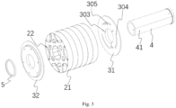
- the present invention provides a drive motor that includes a stator 1, a rotor 2, a balance disc 3, and a rotation shaft 4.
- the stator 1 is fitted over the rotor 2.
- the rotor 2 includes a rotor core 21 and a permanent magnet 22 in the rotor core 21.
- the rotor core 21 has a first end face and a second end face.
- the balance disc 3 includes a first balance disc 31 configured to abut against the first end face and a second balance disc 32 configured to abut against the second end face.
- the first balance disc 31, the rotor core 21 and the second balance disc 32 are fitted over the rotation shaft 4 sequentially along an axial direction and are fixed by a locking member 5 at an end.
- the drive motor may be a permanent magnet synchronous motor and can be applied to various equipment in different industries such as vehicles, metallurgy, environmental protection, etc., which will not be limited in the present invention.
- the locking member 5 may be a nut, a press rivet ring, a circlip, an interference ring, etc., and can achieve axial fixed locking of the balance disc 3 and the rotor core 21 by cooperating with a shoulder of the rotation shaft 4.
- the first balance disc 31 and the second balance disc 32 may have the same structure or different structures, and may be made of materials such as steel, stainless steel and aluminum alloy. The present invention will be described in detail through an example where the locking member 5 is an interference ring and the balance disc 3 is made of aluminum alloy.
- the strength of the balance disc can meet the requirements at a current mainstream speed stage of the drive motor, but as the speed needs to be further increased, the strength of the balance disc becomes a limiting factor.
- the rotation shaft 4 and the balance disc 3 are positioned in a circumferential direction by providing a convex key on an inner ring of the balance disc 3 and providing a keyway on an outer circumferential wall of the rotation shaft 4, and the balance disc 3 and the rotation shaft 4 are locked in the circumferential direction by cooperation between the convex key and the keyway.
- the balance disc 3 and the rotation shaft 4 are positioned in the circumferential direction by an interference fit.
- the balance disc is made of steel or stainless steel, because of a high density of the material and the action of centrifugal force at high speed, the structural strength of the balance disc itself is difficult to meet high-speed scenarios, and the high density causes a growing tendency of outward expansion of the inner ring under the action of centrifugal force, and a requirement for a large amount of interference.
- the strength of the balance disc will become a bottleneck when the amount of interference is increased. Overall, it is difficult to meet the high-speed scenarios.
- the position of the circumferential limiting structure is adjusted in the present invention.
- the circumferential limiting structure is provided between the first balance disc 31 and the first end face, and/or between the second balance disc 32 and the second end surface.
- the circumferential limiting structure includes a convex key 61 and a limiting hole 62 fitted with the convex key 61.
- the drive motor provided by the present invention, by adjusting the position of the circumferential limiting structure, the circumferential locking of the balance disc 3 and the rotor core 21 can be achieved; the problem of stress concentration in the inner ring of the balance disc 3 during high-speed operation can be effectively solved; the strength of silicon steel sheets of the rotor and the strength of the balance disc under high speed can be ensured; the speed increase of the drive motor can be effectively achieved; and hence the power density of the drive motor can be improved.
- conventional rotor production processes which are simple and mature, can be adopted.
- the convex key 61 and the limiting hole 62 may be in an interference fit, so that the balance disc 3 and the rotor core 21 may be prevented from relative movement in the circumferential direction and in the axial direction.
- the rotor core 21 and the rotation shaft 4 are in an interference fit, and the rotor core 21 and the rotation shaft 4 are fixed in a large interference fit or a keyway fit, so that the balance disc 3 and the rotation shaft 4 can be fixed in the circumferential direction.
- the balance disc 3 has a central hole 30 for the rotation shaft 4 to pass through.
- the balance disc 3 is constructed in an annular structure having an inner ring and an outer ring, and the convex key 61 is between the inner ring and the outer ring.
- each convex key 61 has a trapezoidal structure, with an upper bottom and a lower bottom of the trapezoidal structure being perpendicular to a radial direction of the balance disc 3; and each limiting hole 62 is correspondingly a trapezoidal hole.
- the convex key 61 may also have a cylindrical, square or other structure, which will not be limited in the present invention.
- four corners of the trapezoidal structure are designed as rounded corners to facilitate installation of the convex keys 61 and the limiting holes 62.
- the balance disc 3 has the central hole 30 through which the rotation shaft 4 passes.
- An end face of the balance disc provided with the convex key is denoted as a first end face, and another end face opposite to the first end face is denoted as a second end face.
- a stress relief groove 312 is on an outer circumference of the central hole 30 on the first end face, and the stress relief groove 312 is radially outwards from a circumferential wall of the central hole 30 and in connection with the central hole 30. In such a way, the stress at high speed can be effectively relieved while ensuring the stability of connection with the rotation shaft 4.
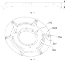
- the oil guide groove 303, the arc oil passage 305, and the oil outlet groove 307 are designed with an identical width "a", and may be designed according to a required flow rate of the cooling liquid.
- the width "a" ranges from 2 mm to 6 mm.
- the oil guide groove 303, the arc oil passage 305, and the oil outlet groove 307 are designed with different widths.
- a plurality of arc oil passages 305 are on the first end face of the balance disc 3,
- R1 represents an outer diameter of the stress relief groove 312, and
- D represents a wall thickness of an intermediate portion 301 of the balance disc 3.
- R1 R4-a-2d.
- the dynamic balance calibration of the balance disc adopts a weight removal method. By the balance calibration and the above dimension design, rotational balance of the balance disc can be ensured and the problem of stress concentration can be solved.
- an end face, away from the convex key 61, of at least one of the first balance disc 31 or the second balance disc 32, that is, the second end face, has the intermediate portion 301 and a lightening portion 302 on a periphery of the intermediate portion 301, and a size of the lightening portion 302 in the axial direction is smaller than a size of the intermediate portion 301 in the axial direction.
- the stress level close to the groove of the inner ring of the balance disc can be greatly improved by the lightening structure of the outer ring of the balance disc.
- the lightening portion 302 is provided with a plurality of radial ribs 3011 extending radially outwards from the intermediate portion 301.
- the plurality of radial ribs 3011 divide the lightening portion 302 into a plurality of lightening zones.
- the oil outlet groove 307 extending in the radial direction on the first end face is at a position corresponding to each radial rib 3011, to avoid the lightening zones.
- the more weight the balance disc loses the more the stress level at high speed lowers. Reducing weight while ensuring structural strength can improve the stress level of the balance disc.
- the oil slinging hole 306 is at an end of each radial rib 3011 and in connection with the oil outlet groove 307.
- the plurality of arc oil passages 305 are arranged on the first end surface, R2 represents an outer diameter of the intermediate portion 301, and R4 represents the outer diameter of each arc oil passage 305, in which R 2 ⁇ R 4 + H .
- the radial rib 3011 may be of any suitable structure. As shown in FIGS. 14 and 15 , the width of the radial rib 3011 is denoted as "c", and the width of the arc oil passage 305 is denoted as "a", in which c ⁇ a+2H.
- the radial rib 3011 is configured to have a width gradually decreasing from inside to outside.
- the width "c" is a minimum width. In such a way, the overall rigidity of the balance disc can be ensured.
- the stator 1 and the rotor 2 in relevant embodiments of the present invention, usually adopt the same silicon steel.
- the mainstream silicon steel has a yield strength of about 450Mpa and an iron loss level of about 14W/kg. With such silicon steel performance, the mainstream drive motor has a speed level of about 16000-18000 rpm, and the speed may be raised to 20000 rpm through stress optimization. However, if it is desired to further increase the speed, the strength of the silicon steel can no longer meet strength requirements.
- the strength and iron loss of the silicon steel are interrelated. It is found that the iron loss of the drive motor mainly comes from the iron loss of the stator 1, followed by an eddy current loss of the permanent magnet 22, and then the iron loss of the rotor 2.
- the following table shows a composition analysis of a permanent magnet synchronous motor, with a stator iron loss accounting for 96% and a rotor iron loss accounting for 4%.
- the stator 1 and the rotor 2 are made of silicon steel materials, and use two types of silicon steel with different properties.
- the different properties mean different types of silicon steel, which can have different carbon or silicon contents, resulting in different strength and hence different iron loss.
- the motor speed is further increased by differentiating the types of silicon steel for the stator and the rotor.
- the balance disc 3 is made of materials such as aluminum alloy, steel, and stainless steel. In terms of the strength, the strength of the balance disc 3, the stator 1 and the rotor 2 increases sequentially.
- the iron loss of the stator 1 is the least, the eddy current loss of the permanent magnet 22 takes the second place, and the iron loss of the rotor 2 is the most. That is, the stator 1 uses a type of silicon steel having small iron loss and mainstream strength, and the rotor 2 uses a type of silicon steel having high strength or even ultra-high strength, and a yield strength of 600Mpa or above, but allows for a moderate increase in iron loss.
- the silicon steel of the stator 1 different from that of the rotor 2, the rotor core 21 can meet the strength requirement at high speed without increasing the air gap between the stator and the rotor and still using a conventional stamping process.
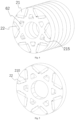
- the rotor core 21 includes a receiving groove 210 for fixing the permanent magnet 22.
- a fixing portion is on an inner wall of the receiving groove 210 and is configured to fix the permanent magnet 22.
- a flow channel 211 for circulation of the cooling liquid is formed between the inner wall of the receiving groove 210 and the permanent magnet 22.
- the cooling liquid may be water-cooled or oil-cooled, or may be other cooling media. As an example, an oil-cooled motor will be described in detail.
- the rotation shaft 4 includes a plurality of oil inlet holes 41; each of two balance discs includes the oil guide groove 303 and the arc oil passage 305; and the oil guide hole 304 is on the rotor core 21 or on the balance disc.
- the arc oil passage 305 is configured to connect flow channels 211 of two adjacent receiving grooves 210.
- the oil guide hole 304 corresponds to the arc oil passage 305 in position.
- a flow path of the oil for cooling the permanent magnet 22 is as follows: the cooling oil is introduced into the hollow rotation shaft 4; the cooling oil is driven to rotate along an inner wall of the rotation shaft 4 along with rotation of the rotor 2; and under the centrifugal force and oil pressure of the cooling oil, the cooling oil enters the oil guide groove 303, formed by the balance disc and the rotor core 21, through the oil inlet hole 41. As shown in FIG. 16 , the cooling oil flows into the oil guide hole 304 through the oil guide groove 303, enters an end of the rotor core 21 (for example, flowing from the first end face to the second end face), and enters the flow channel 211 through the arc oil passage 305, to cool the permanent magnet 22.
- the cooling oil returns to the first end face of the rotor core 21 through the flow channel 211, passes through the oil outlet groove 307, and finally sprays obliquely through the oil slinging hole 306 towards an end winding of the stator 1.
- the following table shows a comparison of temperature of the permanent magnet 22 in three solutions: direct oil feeding of the permanent magnet 22, oil feeding of the rotor core 21, and oil feeding of the rotation shaft 4. It can be clearly seen that the direct oil feeding of the permanent magnet 22 provided in the present invention can reduce the temperature of the permanent magnet 22 and avoid demagnetization caused by high temperature of the permanent magnet 22.
- Oil circuit solution Magnetic steel temperature Rotation shaft oil feeding + iron core oil feeding + magnetic steel oil feeding 129°C Rotation shaft oil feeding + iron core oil feeding 148°C Rotation shaft oil feeding 178°C
- the flow rate of the cooling liquid can be ensured, the rotational balance of the balance disc can be ensured, and a weight reduction design can be realized, improving the overall stress level of the balance disc.
- the permanent magnet 22 is fixed in any suitable manner in the receiving groove 210.
- the receiving groove 210 has a first surface 2101 and a second surface 2102 which are opposite to each other, as well as a first sidewall 2103 and a second sidewall 2104 which are opposite to each other.
- the flow channel 211 is formed between the first sidewall 2103 and a first side surface of the permanent magnet 22 and is also formed between the second sidewall 2104 and a second side surface of the permanent magnet 22.
- the first surface 2101 and the second surface 2102 both abut against the permanent magnet 22, and the permanent magnet 22 is fixed by an interference fit.
- the flow channels 211 are formed while the permanent magnet 22 is stably fixed in the receiving groove 210, and the permanent magnet 22 is in direct contact with the cooling oil to achieve the direct cooling and heat dissipation of the permanent magnet 22.
- the permanent magnet 22 may also be fixed in the receiving groove 210 using methods such as glue dispensing, injection moulding, and epoxy potting.
- the fixing portion may be of any suitable structure.
- a plurality of elastic pieces 212 are on the first surface 2101 and/or the second surface 2102, and the plurality of elastic pieces 212 are spaced apart from each other in the axial direction of the rotor core 21. In this way, after the permanent magnet 22 is inserted in the axial direction, the elastic pieces 212 deform and press against the permanent magnet 22, thereby fixing the permanent magnet 22.
- a pressing point 214 is on the rotor core 21 and at a position close to the first surface 2101 or the second surface 2102 of the receiving groove 210.
- the pressing point 214 of the rotor core 21 is pressed in the axial direction using a pressing head, causing plastic deformation of the rotor core 21, and causing deformation of the first surface 2101 or the second surface 2102 in a direction close to the permanent magnet 22 to form the fixing portion, such that the fixing portion is arched toward an interior of the receiving groove 210 and presses the permanent magnet 22 tightly, achieving mechanical fixation of the permanent magnet 22.
- the flow channels 211 are formed between left and right ends of the permanent magnet and the first sidewall 2103 and the second sidewall 2104 to allow the cooling oil to flow, thereby achieving the direct cooling of the permanent magnet 22.
- limiting protrusions 213 are arranged on the inner wall of the receiving groove 210 and to both sides of the permanent magnet 22.
- the fixation of the permanent magnet 22 is achieved by mutual cooperation among the limiting protrusions 213, the elastic pieces 212 and the pressing point 214.
- one or two of the above three fixing means may be selected, which will not be limited in the present invention.
- a vehicle including the above-described drive motor.
- the drive motor can be applied to new energy vehicles to realize high-speed driving and improve the power density of the drive motor.
- the present invention provides a complete set of optimization solutions from different aspects, such as the strength of the silicon steel sheets, the strength of the balance disc, and the heat dissipation of the rotor, during high-speed rotation of the rotor.
- the production process of conventional rotors may be adopted without increasing production costs, which is relatively simple and mature.
- the vehicle has all the beneficial effects of the above-described drive motor, which will not be described in detail herein.
Landscapes
- Engineering & Computer Science (AREA)
- Power Engineering (AREA)
- Manufacturing & Machinery (AREA)
- Iron Core Of Rotating Electric Machines (AREA)
Applications Claiming Priority (1)
| Application Number | Priority Date | Filing Date | Title |
|---|---|---|---|
| CN202310597842.9A CN116647079B (zh) | 2023-05-24 | 2023-05-24 | 驱动电机和车辆 |
Publications (1)
| Publication Number | Publication Date |
|---|---|
| EP4468567A1 true EP4468567A1 (de) | 2024-11-27 |
Family
ID=87614800
Family Applications (1)
| Application Number | Title | Priority Date | Filing Date |
|---|---|---|---|
| EP23198014.5A Pending EP4468567A1 (de) | 2023-05-24 | 2023-09-18 | Antriebsmotor mit dauermagnetischem rotor zur verwendung in einem fahrzeug |
Country Status (3)
| Country | Link |
|---|---|
| US (1) | US20240396404A1 (de) |
| EP (1) | EP4468567A1 (de) |
| CN (1) | CN116647079B (de) |
Citations (5)
| Publication number | Priority date | Publication date | Assignee | Title |
|---|---|---|---|---|
| EP2597188A1 (de) * | 2010-07-21 | 2013-05-29 | Panasonic Corporation | Bürstenloser motor für eine waschmaschine, damit ausgestattete trommelwaschmaschine sowie verfahren zur herstellung des bürstenlosen motors für eine waschmaschine |
| CN208539677U (zh) * | 2018-07-26 | 2019-02-22 | 广东威灵电机制造有限公司 | 永磁电机转子和永磁电机 |
| CN109861446A (zh) * | 2019-02-18 | 2019-06-07 | 浙江龙芯电驱动科技有限公司 | 一种电机内冷却转子动平衡板结构 |
| WO2021225902A1 (en) * | 2020-05-04 | 2021-11-11 | Tesla, Inc. | Permanent magnet motor with wrapping |
| JP2022051837A (ja) * | 2018-03-12 | 2022-04-01 | 三菱電機株式会社 | 電動機、圧縮機、送風機、及び冷凍空調装置 |
Family Cites Families (16)
| Publication number | Priority date | Publication date | Assignee | Title |
|---|---|---|---|---|
| JP2007037202A (ja) * | 2003-10-31 | 2007-02-08 | Neomax Co Ltd | 永久磁石埋め込み型モータ用回転子、その組立方法および組立装置 |
| CN101305510B (zh) * | 2005-11-09 | 2011-08-10 | 株式会社东芝 | 旋转电机用转子及旋转电机 |
| KR20080089882A (ko) * | 2007-04-03 | 2008-10-08 | 삼성전자주식회사 | 전동기 |
| US20120133230A1 (en) * | 2010-11-30 | 2012-05-31 | Patrick Lee Jansen | Split-pole magnetic module for electric machine rotors |
| KR101967648B1 (ko) * | 2017-12-15 | 2019-04-10 | 엘지전자 주식회사 | 전동기의 로터 조립체 |
| CN207819585U (zh) * | 2018-02-26 | 2018-09-04 | 广东亚捷节能环保科技有限公司 | 一种嵌入式的永磁电机永磁体 |
| US10790721B2 (en) * | 2018-06-04 | 2020-09-29 | Abb Schweiz Ag | Bonded rotor shaft |
| CN114552832B (zh) * | 2020-11-27 | 2023-09-05 | 比亚迪股份有限公司 | 电机 |
| US12609572B2 (en) * | 2020-12-23 | 2026-04-21 | Lg Electronics Inc. | Stator of rotating electric machine |
| CN214281075U (zh) * | 2021-03-25 | 2021-09-24 | 上海汽车集团股份有限公司 | 一种电机及电机的转子铁芯与转轴固定结构 |
| CN113206563A (zh) * | 2021-04-21 | 2021-08-03 | 浙江零跑科技有限公司 | 一种油冷电驱动力转子结构 |
| CN114744788B (zh) * | 2022-03-28 | 2022-12-27 | 小米汽车科技有限公司 | 油冷电机 |
| CN115459493A (zh) * | 2022-09-23 | 2022-12-09 | 南京泉峰汽车精密技术股份有限公司 | 一种驱动电机的油冷结构 |
| CN115589086A (zh) * | 2022-10-11 | 2023-01-10 | 东风汽车集团股份有限公司 | 一种高速电机转子总成的增强、冷却润滑结构、转子总成及电机 |
| JP7816110B2 (ja) * | 2022-12-07 | 2026-02-18 | トヨタ自動車株式会社 | モータ |
| CN219718023U (zh) * | 2023-05-24 | 2023-09-19 | 小米汽车科技有限公司 | 平衡盘、驱动电机和车辆 |
-
2023
- 2023-05-24 CN CN202310597842.9A patent/CN116647079B/zh active Active
- 2023-09-05 US US18/242,266 patent/US20240396404A1/en active Pending
- 2023-09-18 EP EP23198014.5A patent/EP4468567A1/de active Pending
Patent Citations (5)
| Publication number | Priority date | Publication date | Assignee | Title |
|---|---|---|---|---|
| EP2597188A1 (de) * | 2010-07-21 | 2013-05-29 | Panasonic Corporation | Bürstenloser motor für eine waschmaschine, damit ausgestattete trommelwaschmaschine sowie verfahren zur herstellung des bürstenlosen motors für eine waschmaschine |
| JP2022051837A (ja) * | 2018-03-12 | 2022-04-01 | 三菱電機株式会社 | 電動機、圧縮機、送風機、及び冷凍空調装置 |
| CN208539677U (zh) * | 2018-07-26 | 2019-02-22 | 广东威灵电机制造有限公司 | 永磁电机转子和永磁电机 |
| CN109861446A (zh) * | 2019-02-18 | 2019-06-07 | 浙江龙芯电驱动科技有限公司 | 一种电机内冷却转子动平衡板结构 |
| WO2021225902A1 (en) * | 2020-05-04 | 2021-11-11 | Tesla, Inc. | Permanent magnet motor with wrapping |
Also Published As
| Publication number | Publication date |
|---|---|
| CN116647079A (zh) | 2023-08-25 |
| CN116647079B (zh) | 2024-03-26 |
| US20240396404A1 (en) | 2024-11-28 |
Similar Documents
| Publication | Publication Date | Title |
|---|---|---|
| US7019428B2 (en) | Induction motor and rotor therefor | |
| CN108988534B (zh) | 一种高速永磁电机转子及其加工方法 | |
| JP2002369425A (ja) | 永久磁石回転子 | |
| EP4007132B1 (de) | Vorrichtung zum vermindern der umfangstemperaturdifferenz zwischen spule und kern eines motors mit grossem durchmesser | |
| US20240128814A1 (en) | Rotor disk and manufacturing method thereof, rotor structure, disk motor, and electric vehicle | |
| US11303168B2 (en) | Rotor of rotary electric machine | |
| EP4468567A1 (de) | Antriebsmotor mit dauermagnetischem rotor zur verwendung in einem fahrzeug | |
| US7546674B2 (en) | Method of rotor assembly without the hub | |
| JP4003228B2 (ja) | 空冷モータ | |
| JP5772415B2 (ja) | 回転電機のロータ構造 | |
| EP4560890A1 (de) | Rotoranordnung, elektromotor und neuenergiefahrzeug | |
| KR20250168603A (ko) | 축방향 필드 모터 | |
| JP2010074979A (ja) | 回転電動機 | |
| CN207782515U (zh) | 定子冲片及定子铁心 | |
| JP7607290B2 (ja) | ロータ | |
| JP7504320B1 (ja) | モータ | |
| JP7329721B1 (ja) | 回転電機 | |
| CN112152358A (zh) | 转子冲片、转子铁芯、电机和压缩机 | |
| US20080067027A1 (en) | Electromagnetic clutch | |
| KR20170053250A (ko) | 스포크 타입 회전자 | |
| CN220172947U (zh) | 一种辐板轴电机转子散热机构 | |
| CN223024240U (zh) | 一种转子结构、电机及压缩机 | |
| CN222321214U (zh) | 一种用于电机转子的安装件及电机转子 | |
| US20030209946A1 (en) | Heat-dissipated mechanism for outer-rotor type brushless DC motor | |
| KR20250070747A (ko) | 영구자석 동기전동기 |
Legal Events
| Date | Code | Title | Description |
|---|---|---|---|
| PUAI | Public reference made under article 153(3) epc to a published international application that has entered the european phase |
Free format text: ORIGINAL CODE: 0009012 |
|
| STAA | Information on the status of an ep patent application or granted ep patent |
Free format text: STATUS: REQUEST FOR EXAMINATION WAS MADE |
|
| 17P | Request for examination filed |
Effective date: 20230918 |
|
| AK | Designated contracting states |
Kind code of ref document: A1 Designated state(s): AL AT BE BG CH CY CZ DE DK EE ES FI FR GB GR HR HU IE IS IT LI LT LU LV MC ME MK MT NL NO PL PT RO RS SE SI SK SM TR |